EP1501153A1 - Méthode et dispositif de controle d'alignement d'une antenne - Google Patents
Méthode et dispositif de controle d'alignement d'une antenne Download PDFInfo
- Publication number
- EP1501153A1 EP1501153A1 EP04017505A EP04017505A EP1501153A1 EP 1501153 A1 EP1501153 A1 EP 1501153A1 EP 04017505 A EP04017505 A EP 04017505A EP 04017505 A EP04017505 A EP 04017505A EP 1501153 A1 EP1501153 A1 EP 1501153A1
- Authority
- EP
- European Patent Office
- Prior art keywords
- antenna
- monitoring
- earth
- magnetic field
- monitoring center
- Prior art date
- Legal status (The legal status is an assumption and is not a legal conclusion. Google has not performed a legal analysis and makes no representation as to the accuracy of the status listed.)
- Withdrawn
Links
- 238000000034 method Methods 0.000 title claims description 11
- 230000005291 magnetic effect Effects 0.000 claims abstract description 25
- 238000012544 monitoring process Methods 0.000 claims abstract description 18
- 238000009434 installation Methods 0.000 claims abstract 4
- 230000005358 geomagnetic field Effects 0.000 claims description 11
- 238000005259 measurement Methods 0.000 claims description 7
- 238000004891 communication Methods 0.000 claims description 5
- 230000002123 temporal effect Effects 0.000 claims description 4
- XEEYBQQBJWHFJM-UHFFFAOYSA-N Iron Chemical compound [Fe] XEEYBQQBJWHFJM-UHFFFAOYSA-N 0.000 description 4
- 239000013598 vector Substances 0.000 description 3
- 230000001413 cellular effect Effects 0.000 description 2
- 238000011156 evaluation Methods 0.000 description 2
- 229910052742 iron Inorganic materials 0.000 description 2
- 238000005452 bending Methods 0.000 description 1
- 230000005540 biological transmission Effects 0.000 description 1
- 238000010276 construction Methods 0.000 description 1
- 238000001514 detection method Methods 0.000 description 1
- 230000005294 ferromagnetic effect Effects 0.000 description 1
- 230000007774 longterm Effects 0.000 description 1
- 239000002184 metal Substances 0.000 description 1
- 229910052751 metal Inorganic materials 0.000 description 1
- 238000012552 review Methods 0.000 description 1
Images
Classifications
-
- H—ELECTRICITY
- H01—ELECTRIC ELEMENTS
- H01Q—ANTENNAS, i.e. RADIO AERIALS
- H01Q1/00—Details of, or arrangements associated with, antennas
- H01Q1/12—Supports; Mounting means
- H01Q1/125—Means for positioning
-
- H—ELECTRICITY
- H01—ELECTRIC ELEMENTS
- H01Q—ANTENNAS, i.e. RADIO AERIALS
- H01Q3/00—Arrangements for changing or varying the orientation or the shape of the directional pattern of the waves radiated from an antenna or antenna system
- H01Q3/005—Arrangements for changing or varying the orientation or the shape of the directional pattern of the waves radiated from an antenna or antenna system using remotely controlled antenna positioning or scanning
Definitions
- the invention relates to an apparatus and a method for monitoring the orientation of an antenna system, in particular a mobile radio antenna system.
- US 5 790 075 discloses a method and a device for measuring the orientation of an antenna based on data from a magnetic field detector known.
- a reference measurement is carried out in advance, at the antenna must be rotated 360 ° once, while the horizontal and / or vertical component of the earth's magnetic field by means of the sensor is measured. Thereafter, by comparing the current from the sensor measured geomagnetic field data with the previously stored reference data and off the direction of rotation of the antenna whose current orientation is determined.
- the object of the invention is a reliable monitoring of the alignment allow mobile radio antenna systems with little effort.
- the invention provides to detect the position of an antenna via the earth's magnetic field.
- the disturbing influences by iron masts or other electromagnetic influences is with Help compensate for calibration in a given position of the antenna.
- the invention enables a simple and constant monitoring of the antennas e.g. from the base of an antenna mast of the plant or via a remote diagnostic system.
- the antenna system can be monitored during operation, as a Do not enter the antenna system and work with ladders or lifting vehicles necessary.
- eliminating the construction of a complicated measuring device e.g., for a bearing measurement).
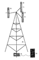
- the antenna system shown in the figure comprises an antenna mast 6, on the multiple antennas 1 are mounted.
- monitoring units 2 which is an electronic earth magnetic field sensor, a Microcontroller and an interface for communication with an over-whelm headquarters 3.
- the electronic magnetic field sensor that is at the Antenna detected 1 existing geomagnetic field.
- a possible failure by Metal masses is compensated by the calibration of the sensor, wherein the Target state as "normal zero" stored in the EEPROM of the microcontroller becomes.
- the microcontroller constantly measures the deviation from this calibrated one Position and triggers an alarm when exceeding a set tolerance. The exceeding is communicated to the monitoring center 3, this is this visually and / or acoustically signaled.
- the monitoring center 3 allows also a forwarding to downstream devices 5.
- the positional deviation of the antenna 1 is according to the invention without external Calibration (e.g., by rotating the antenna or the like).
- the calibration refers to the assumption of the (once set) nominal position of the Antenna 1. This position of the antenna 1 is by the specifications of the user certainly. If the antenna 1 is mounted, the corresponding values are displayed as Preset position (reference data) stored. Subsequently, the Orientation of the antenna 1 monitored by means of the geomagnetic field sensor by comparing the currently measured values with the reference data become.
- the variables O, N and Z give the space vectors East, North and Top (Gravitational vector).
- WMM World Magnetic Model
- Another parameter to consider is the current time.
- false alarms of the device may be due to a disregard Such deviations of the earth's magnetic field are due avoided become.
- the invention allows, independent of the vertical and horizontal Able, a correct indication of the direction of the compass with respect to the antenna 1, where errors of the magnetic field vector due to spatial and temporal Deviations or changes in the Earth's magnetic field and due to ferromagnetic Influences are compensated. This becomes an absolute independence reached by fixed or mobile aids.
Landscapes
- Support Of Aerials (AREA)
- Variable-Direction Aerials And Aerial Arrays (AREA)
- Position Fixing By Use Of Radio Waves (AREA)
Applications Claiming Priority (2)
| Application Number | Priority Date | Filing Date | Title |
|---|---|---|---|
| DE20311407U DE20311407U1 (de) | 2003-07-24 | 2003-07-24 | Vorrichtung zur Überprüfung der Ausrichtung einer Antennenanlage |
| DE20311407U | 2003-07-24 |
Publications (1)
| Publication Number | Publication Date |
|---|---|
| EP1501153A1 true EP1501153A1 (fr) | 2005-01-26 |
Family
ID=28051643
Family Applications (1)
| Application Number | Title | Priority Date | Filing Date |
|---|---|---|---|
| EP04017505A Withdrawn EP1501153A1 (fr) | 2003-07-24 | 2004-07-23 | Méthode et dispositif de controle d'alignement d'une antenne |
Country Status (2)
| Country | Link |
|---|---|
| EP (1) | EP1501153A1 (fr) |
| DE (1) | DE20311407U1 (fr) |
Cited By (5)
| Publication number | Priority date | Publication date | Assignee | Title |
|---|---|---|---|---|
| EP2001145A4 (fr) * | 2006-03-28 | 2009-12-16 | Kyocera Corp | Dispositif de station de base et procédé de détection d'erreur d'installation de dispositif de station de base |
| RU2476962C2 (ru) * | 2011-06-08 | 2013-02-27 | Открытое акционерное общество Центральное конструкторское бюро аппаратостроения | Коаксиальная линия |
| RU2544764C2 (ru) * | 2012-07-31 | 2015-03-20 | Открытое акционерное общество Центральное конструкторское бюро аппаратостроения | Коаксиальный тракт |
| US10396426B2 (en) | 2013-08-27 | 2019-08-27 | Commscope Technologies Llc | Alignment determination for antennas |
| WO2022008105A1 (fr) * | 2020-07-08 | 2022-01-13 | Nokia Technologies Oy | Étalonnage d'erreurs d'orientation de faisceau pour un positionnement amélioré |
Families Citing this family (2)
| Publication number | Priority date | Publication date | Assignee | Title |
|---|---|---|---|---|
| US8471780B2 (en) | 2008-12-24 | 2013-06-25 | Enzo Dalmazzo | Autonomous wireless antenna sensor system |
| US8766872B2 (en) * | 2008-12-24 | 2014-07-01 | Enzo Dalmazzo | Autonomous wireless antenna sensor system |
Citations (5)
| Publication number | Priority date | Publication date | Assignee | Title |
|---|---|---|---|---|
| US3739364A (en) * | 1971-06-07 | 1973-06-12 | Texas Instruments Inc | Antenna mast misalignment detector |
| US5790075A (en) * | 1994-09-09 | 1998-08-04 | Software Design Ltd. | Beam antenna direction measuring method, direction measuring device and antenna direction controller |
| US6016120A (en) * | 1998-12-17 | 2000-01-18 | Trimble Navigation Limited | Method and apparatus for automatically aiming an antenna to a distant location |
| EP1067626A2 (fr) * | 1999-06-30 | 2001-01-10 | Radio Frequency Systems, Inc. | Système d'antenne à télécommande d' inclinaison de faisceau |
| EP1231668A2 (fr) * | 2001-02-08 | 2002-08-14 | Mitsubishi Denki Kabushiki Kaisha | Dispositif et procédé de commande d'antenne |
Family Cites Families (2)
| Publication number | Priority date | Publication date | Assignee | Title |
|---|---|---|---|---|
| FR2656416B1 (fr) | 1989-12-22 | 1993-02-05 | Alcatel Transmission | Dispositif de mesure des mouvements de flexion d'un mat support d'antenne et application a la commande du pointage d'une antenne motorisee. |
| US6195559B1 (en) | 1997-11-26 | 2001-02-27 | U.S. Philips Corporation | Communication system, a primary radio station, a secondary radio station, and a communication method |
-
2003
- 2003-07-24 DE DE20311407U patent/DE20311407U1/de not_active Expired - Lifetime
-
2004
- 2004-07-23 EP EP04017505A patent/EP1501153A1/fr not_active Withdrawn
Patent Citations (5)
| Publication number | Priority date | Publication date | Assignee | Title |
|---|---|---|---|---|
| US3739364A (en) * | 1971-06-07 | 1973-06-12 | Texas Instruments Inc | Antenna mast misalignment detector |
| US5790075A (en) * | 1994-09-09 | 1998-08-04 | Software Design Ltd. | Beam antenna direction measuring method, direction measuring device and antenna direction controller |
| US6016120A (en) * | 1998-12-17 | 2000-01-18 | Trimble Navigation Limited | Method and apparatus for automatically aiming an antenna to a distant location |
| EP1067626A2 (fr) * | 1999-06-30 | 2001-01-10 | Radio Frequency Systems, Inc. | Système d'antenne à télécommande d' inclinaison de faisceau |
| EP1231668A2 (fr) * | 2001-02-08 | 2002-08-14 | Mitsubishi Denki Kabushiki Kaisha | Dispositif et procédé de commande d'antenne |
Cited By (7)
| Publication number | Priority date | Publication date | Assignee | Title |
|---|---|---|---|---|
| EP2001145A4 (fr) * | 2006-03-28 | 2009-12-16 | Kyocera Corp | Dispositif de station de base et procédé de détection d'erreur d'installation de dispositif de station de base |
| US8060146B2 (en) | 2006-03-28 | 2011-11-15 | Kyocera Corporation | Base station device and base station device installation error detection method |
| RU2476962C2 (ru) * | 2011-06-08 | 2013-02-27 | Открытое акционерное общество Центральное конструкторское бюро аппаратостроения | Коаксиальная линия |
| RU2544764C2 (ru) * | 2012-07-31 | 2015-03-20 | Открытое акционерное общество Центральное конструкторское бюро аппаратостроения | Коаксиальный тракт |
| US10396426B2 (en) | 2013-08-27 | 2019-08-27 | Commscope Technologies Llc | Alignment determination for antennas |
| WO2022008105A1 (fr) * | 2020-07-08 | 2022-01-13 | Nokia Technologies Oy | Étalonnage d'erreurs d'orientation de faisceau pour un positionnement amélioré |
| US11882466B2 (en) | 2020-07-08 | 2024-01-23 | Nokia Technologies Oy | Calibrating beam orientation errors for improved positioning |
Also Published As
| Publication number | Publication date |
|---|---|
| DE20311407U1 (de) | 2003-09-11 |
Similar Documents
| Publication | Publication Date | Title |
|---|---|---|
| DE4242541A1 (de) | Vorrichtung zum Orten unterhalb der Erdoberfläche befindlicher Munition | |
| EP3056923A1 (fr) | Systeme de balayage et procede de balayage d'un objet | |
| DE102005017320A1 (de) | Verfahren zum Schätzen der Genauigkeit azimutaler Ausrichtungen und tragbares Zielgerät | |
| EP0474799B1 (fr) | Procede et dispositif permettant de controler le parallelisme d'axes de corps | |
| WO2016113411A1 (fr) | Dispositif de localisation et procédé de localisation | |
| DE102013104727A1 (de) | Verfahren und Vorrichtungen zum Bestimmen der Position einer beweglichen Kommunikationseinrichtung | |
| EP0807805A2 (fr) | Procédé pour calibrer une balance | |
| EP3115738A1 (fr) | Appareil de mesure optoelectronique et procede de detection de pannes | |
| DE3734057C2 (fr) | ||
| EP1501153A1 (fr) | Méthode et dispositif de controle d'alignement d'une antenne | |
| EP3561458A1 (fr) | Procédé de détection de répartition spatiale d'une grandeur physique mesurable | |
| EP3249353B1 (fr) | Appareil de mesure optoélectrique dote d'un compas magnétique et fonctionnalité de compensation | |
| EP1921469A2 (fr) | Agencement de capteur optoélectrique et procédé d'ajustement d'un agencement de capteur optoélectrique | |
| EP1153314B1 (fr) | Procede et dispositif pour determiner une position | |
| DE102013004640A1 (de) | Fahrgastbrücke | |
| EP3217629A1 (fr) | Re-homologation de jauges de niveau de remplissage dans un portail internet | |
| EP3367059A1 (fr) | Appareil de mesure optoelectrique dote d'un compas magnetique et fonctionnalite de compensation | |
| DE102008058866B4 (de) | Vorrichtung und Verfahren zur Lagebestimmung eines Objekts | |
| WO2024056802A1 (fr) | Appareil de maintien de panneau d'étalonnage | |
| EP3435108B1 (fr) | Procédé de recherche d'un appareil d'envoi à l'aide d'un appareil de recherche et appareil de recherche destiné à exécuter un tel procédé | |
| DE202022104997U1 (de) | System mit autonomem Fahrzeug und zweikanaligem Navigationssystem | |
| DE102013218775B4 (de) | System zum Ausrichten einer Richtfunkantenne | |
| DE4312670A1 (de) | Vorrichtung zur Ortsbestimmung eines beweglichen Objektes | |
| EP1174699A1 (fr) | Procédé et dispositif pour tester la solidité de mâts debout ancrés | |
| EP1174838B1 (fr) | Procédé et dispositif pour installer des appareils périphériques |
Legal Events
| Date | Code | Title | Description |
|---|---|---|---|
| PUAI | Public reference made under article 153(3) epc to a published international application that has entered the european phase |
Free format text: ORIGINAL CODE: 0009012 |
|
| AK | Designated contracting states |
Kind code of ref document: A1 Designated state(s): AT BE BG CH CY CZ DE DK EE ES FI FR GB GR HU IE IT LI LU MC NL PL PT RO SE SI SK TR |
|
| AX | Request for extension of the european patent |
Extension state: AL HR LT LV MK |
|
| 17P | Request for examination filed |
Effective date: 20050715 |
|
| AKX | Designation fees paid |
Designated state(s): AT BE BG CH CY CZ DE DK EE ES FI FR GB GR HU IE IT LI LU MC NL PL PT RO SE SI SK TR |
|
| STAA | Information on the status of an ep patent application or granted ep patent |
Free format text: STATUS: THE APPLICATION IS DEEMED TO BE WITHDRAWN |
|
| 18D | Application deemed to be withdrawn |
Effective date: 20060221 |