EP1501169A2 - Elektrische Maschine in Hybridbauweise mit System und Verfahren zu ihrer Regelung - Google Patents
Elektrische Maschine in Hybridbauweise mit System und Verfahren zu ihrer Regelung Download PDFInfo
- Publication number
- EP1501169A2 EP1501169A2 EP04076157A EP04076157A EP1501169A2 EP 1501169 A2 EP1501169 A2 EP 1501169A2 EP 04076157 A EP04076157 A EP 04076157A EP 04076157 A EP04076157 A EP 04076157A EP 1501169 A2 EP1501169 A2 EP 1501169A2
- Authority
- EP
- European Patent Office
- Prior art keywords
- machine
- rotor
- field coil
- mode
- switching devices
- Prior art date
- Legal status (The legal status is an assumption and is not a legal conclusion. Google has not performed a legal analysis and makes no representation as to the accuracy of the status listed.)
- Withdrawn
Links
Images



Classifications
-
- H—ELECTRICITY
- H02—GENERATION; CONVERSION OR DISTRIBUTION OF ELECTRIC POWER
- H02K—DYNAMO-ELECTRIC MACHINES
- H02K21/00—Synchronous motors having permanent magnets; Synchronous generators having permanent magnets
- H02K21/02—Details
- H02K21/04—Windings on magnets for additional excitation ; Windings and magnets for additional excitation
- H02K21/042—Windings on magnets for additional excitation ; Windings and magnets for additional excitation with permanent magnets and field winding both rotating
- H02K21/044—Rotor of the claw pole type
-
- F—MECHANICAL ENGINEERING; LIGHTING; HEATING; WEAPONS; BLASTING
- F02—COMBUSTION ENGINES; HOT-GAS OR COMBUSTION-PRODUCT ENGINE PLANTS
- F02N—STARTING OF COMBUSTION ENGINES; STARTING AIDS FOR SUCH ENGINES, NOT OTHERWISE PROVIDED FOR
- F02N11/00—Starting of engines by means of electric motors
-
- H—ELECTRICITY
- H02—GENERATION; CONVERSION OR DISTRIBUTION OF ELECTRIC POWER
- H02K—DYNAMO-ELECTRIC MACHINES
- H02K16/00—Machines with more than one rotor or stator
- H02K16/02—Machines with one stator and two or more rotors
-
- H—ELECTRICITY
- H02—GENERATION; CONVERSION OR DISTRIBUTION OF ELECTRIC POWER
- H02P—CONTROL OR REGULATION OF ELECTRIC MOTORS, ELECTRIC GENERATORS OR DYNAMO-ELECTRIC CONVERTERS; CONTROLLING TRANSFORMERS, REACTORS OR CHOKE COILS
- H02P6/00—Arrangements for controlling synchronous motors or other dynamo-electric motors using electronic commutation dependent on the rotor position; Electronic commutators therefor
- H02P6/14—Electronic commutators
- H02P6/15—Controlling commutation time
-
- F—MECHANICAL ENGINEERING; LIGHTING; HEATING; WEAPONS; BLASTING
- F02—COMBUSTION ENGINES; HOT-GAS OR COMBUSTION-PRODUCT ENGINE PLANTS
- F02N—STARTING OF COMBUSTION ENGINES; STARTING AIDS FOR SUCH ENGINES, NOT OTHERWISE PROVIDED FOR
- F02N11/00—Starting of engines by means of electric motors
- F02N11/08—Circuits specially adapted for starting of engines
- F02N11/087—Details of the switching means in starting circuits, e.g. relays or electronic switches
- F02N2011/0874—Details of the switching means in starting circuits, e.g. relays or electronic switches characterised by said switch being an electronic switch
-
- H—ELECTRICITY
- H02—GENERATION; CONVERSION OR DISTRIBUTION OF ELECTRIC POWER
- H02K—DYNAMO-ELECTRIC MACHINES
- H02K19/00—Synchronous motors or generators
- H02K19/16—Synchronous generators
- H02K19/22—Synchronous generators having windings each turn of which co-operates alternately with poles of opposite polarity, e.g. heteropolar generators
-
- H—ELECTRICITY
- H02—GENERATION; CONVERSION OR DISTRIBUTION OF ELECTRIC POWER
- H02K—DYNAMO-ELECTRIC MACHINES
- H02K21/00—Synchronous motors having permanent magnets; Synchronous generators having permanent magnets
- H02K21/12—Synchronous motors having permanent magnets; Synchronous generators having permanent magnets with stationary armatures and rotating magnets
- H02K21/14—Synchronous motors having permanent magnets; Synchronous generators having permanent magnets with stationary armatures and rotating magnets with magnets rotating within the armatures
Definitions
- the present invention is generally related to dynamoelectric machines, such as motors and generators, and, more particularly to electrical machines having hybrid rotors, i.e., both electrical and permanent magnet excitation, and system and method for controlling such hybrid machines.
- vehicular propulsion systems are generally configured with a starter for starting the engine, and a separate generator, for generating electric power to supply electrical loads onboard the vehicle, and recharge one or more batteries in the vehicle. While the vehicle is stopped, a significant amount of fuel may be used and pollutants are emitted into the environment. To alleviate this problem, vehicular propulsion architectures have been proposed which utilize a transmission-mounted electric machine to function both as starting motor and electric generator. When the vehicle is stopped, the engine would momentarily shut down and would be restarted when the driver removes his foot from the brake, thus increasing fuel economy and reducing the discharge of emissions into the environment.
- the present invention fulfills the foregoing needs by providing in one aspect thereof a hybrid electrical machine comprising a rotor having at least one field coil for generating a first magnetic flux component in response to current passing therethrough.
- the rotor in turn comprises first and second clawpole segments for encasing the field coil.
- the rotor further comprises at least one permanent magnet radially disposed at an end section thereof for creating a second magnetic flux component, wherein the permanent magnet is embedded within the end section of the rotor.
- a stator is configured to electromagnetically link the first and second flux components from said at least one field coil and the permanent magnet.
- the present invention further fulfills the foregoing needs by providing in another aspect thereof a rotor for an electric machine.
- the rotor comprises at least one field coil for generating a first magnetic flux component in response to current passing therethrough.
- the rotor further comprises first and second clawpole segments for encasing the field coil.
- At least one permanent magnet is radially disposed at an end section of the rotor for creating a second magnetic flux component, wherein the permanent magnet comprises a plurality of permanent magnets embedded in cutouts provided at said end section of the rotor.
- a method for controlling an electrical hybrid machine is provided. The method provides a plurality of control modes for operating the hybrid machine. At least one operational parameter indicative of an operational condition of the machine is sensed.
- An appropriate control mode is selected for the machine in response to the sensed operational parameter.
- a first set of gating pulses is generated for energizing at least one field coil.
- a second set of gating pulses is generated for energizing at least one stator phase, wherein at least one of the first and second sets of gating pulses is configured to perform the selected control mode for the machine.
- a system for controlling an electrical hybrid machine comprises a machine controller configured to provide a plurality of control modes for operating the hybrid machine.
- the system further comprises means for sensing at least one operational parameter indicative of an operational condition of the machine.
- the machine controller is further configured to select an appropriate control mode for the machine in response to the sensed operational parameter.
- a field power bridge is configured to generate a first set of gating pulses for energizing the at least one field coil.
- a stator power bridge is configured to generate a second set of gating pulses for energizing the at least one stator phase, wherein at least one of the first and second sets of gating pulses is configured to perform the selected control mode for the machine.
- aspects of the present invention are directed to increasing an electrical machine's output without a proportional increase in size and weight by using a permanent magnetic field to supplement an electrically-generated rotor field.
- the machine comprises a hybrid Lundell-type electrical machine characterized by a rotor whose magnetic field is established using one or more field coils and one or more permanent magnets.
- a Lundell-type generator rotor includes a bobbin-wound field coil mounted on a rotor shaft to generate a magnetic field.
- the magnetic field flux may be transferred through two claw-type rotor segments forming the north and south poles, respectively, of the magnet thus-created.
- the magnetized rotor assembly spins inside a stator having a number of windings which are "cut" by the magnetized rotor's flux lines so as to induce an electrical current in the stator windings.
- the output of a Lundell-type generator is a function of the rotor magnetization, among other parameters.
- Rotor magnetization is a function of the magnetic field strength in the rotor, which, in turn, is a function of the field coil excitation current. That is, by increasing the field coil excitation current, and thereby increasing the induced magnetic field strength in the claw segments, the rotor magnetization can be increased.
- the magnetization of the claw segments can be increased only up to a certain level, based on the size and material composition of the claw segments, beyond which the claw segments become magnetically saturated. Once the claw segments become saturated, their magnetization does not continue to increase with increased magnetic field strength. Therefore, as a practical matter, the maximum rotor magnetization in a conventional Lundell-type generator is a function of the rotor's size and, more particularly, the claw segments' size.
- Permanent magnets can be used in lieu of a field coil to magnetize a generator rotor, and they can provide greater rotor magnetization than a field coil of comparable size. However, the output voltage of a generator using only a permanent magnet to establish rotor magnetization may not be easily controlled.
- aspects of the present invention are directed to control techniques for a hybrid electrical machine whose rotor magnetization is established using a combination of one or more electrically excitable field coils and one or more permanent magnets.
- the permanent magnet provides a base level of rotor magnetization.
- the rotor's magnetization can be increased above the base level of magnetization provided by the permanent magnet, subject to the limitations discussed above, by electrically exciting the field coil. Since a permanent magnet of a given size can produce a greater level of rotor magnetization than a field coil/claw segment assembly of the same size, a hybrid rotor according to aspects of the present invention can achieve a higher level of magnetization than a conventional rotor of the same size.
- a hybrid rotor according to aspects of the present invention having a predetermined level of magnetization can be smaller and lighter than a conventional Lundell-type rotor having the same level of magnetization.
- FIG. 1 is a cutaway view that illustrates one exemplary embodiment of a hybrid electric machine 10 according to aspects of the present invention.
- a hybrid rotor 11 comprises a shaft 12, a field coil 14, a first claw segment 16 and a second claw segment 18.
- Field coil 14 is located on shaft 12 between first and second claw segments 16 and 18.
- Each of first and second claw segments 16 and 18 includes a plurality of axially extending fingers, such as finger 19.
- the fingers of first claw segment 16 are interleaved with the fingers of second claw segment 18 to substantially encase field coil 14.
- the machine further comprises a plurality of radially-arranged discrete permanent magnets 20 having a number of poles equal to twice the number of claw fingers 19 on claw segments 16 and 18.
- the plurality of permanent magnets is radially embedded (e.g., buried) within appropriately configured cutouts 22 (FIGS. 2 and 3) constructed in a section of the rotor 11.
- the rotor may comprise a plurality of laminations (e.g., lamination 24) pressed onto the rotor shaft. As shown in FIGS. 2 and 3, there would be appropriately configured openings cut in a number of stacked laminations so as to define each cutout 22 for receiving each magnet.
- the cutouts may be configured for holding rectangular-shaped magnets.
- the cutouts may be configured for holding loaf-shaped magnets. It is believed that reluctance effects are more pronounced in the rectangular magnets and cutouts and accordingly such an embodiment would provide a relatively higher contribution of torque production due to such reluctance effects.
- the reluctance difference, as seen from the stator phase conductors, between a low reluctance condition where the stator phase conductors are aligned with the center of the rotor magnet (e.g., the so-called quadrature axis) and a high reluctance condition when the stator phase conductors are aligned with the spacing or break between rotor magnets (e.g., the so-called direct axis) is generally greater in the configuration with the rectangular-shaped magnets than the loaf-shaped magnet.
- This technique of burying the magnets within the rotor provides a two-fold advantage. It provides a more reliable and structurally simple way for mechanically retaining the permanent magnets relative to the rotor and it provides the opportunity for additional shaft torque through the production of reluctance torque.
- the technique of burying the magnets within the rotor advantageously creates a series of flux paths that collectively enhance torque production. More specifically, one would not only get torque production due to flux from the permanent magnets as well as the Lundell coils, but this technique introduces reluctance effects that give rise to a reluctance torque component.
- the rotor section having embedded magnets would create a path of low reluctance followed by a path of high reluctance and each of such paths of high reluctance and low reluctance are successively repeated throughout the circumference of the rotor.
- the stator When the stator is energized, the stator would try to pull the rotor around to align it with any path of low reluctance. Essentially, the rotor would be continuously pulled around and trying to catch up with a rotating flux vector from the stator.
- the end result is that due to the rotor construction comprising cutouts for embedding the magnets within the rotor, one introduces reluctance effects and advantageously obtains a reluctance torque contribution in addition to the torque contributions due to the hybrid characteristics of the machine. That is, torque contributions due to the permanent magnets and the field coil.
- electric machine 10 comprises a clawpole wound rotor section, as a typical Lundell machine, and a permanent magnet rotor section wherein the permanent magnets are embedded within the machine.
- claw segments comprising an axially-extending shelf for supporting the discrete magnets, or use of a magnetized ring in lieu of discrete magnets.
- a stator 26 with respective stator coils 28 links the flux from both rotor sections, which may be aligned such that when positive current is flowing in the rotor field coil, the respective EMF contributions due to the permanent magnet and the field coil are substantially in phase with one another.
- the stator coils may be optionally wound either in a delta configuration or in a wye configuration depending on the requirements of any given application.
- FIG. 4 is a block diagram of an exemplary control system 200 embodying aspects of the present invention for controlling hybrid machine 10.
- a machine controller 202 is coupled to receive commands from a system controller 204.
- system controller 204 may provide a command signal indicative of whether a motoring mode or a power generating mode is desired for hybrid machine 10.
- system controller 204 may provide a command signal indicative of a charging voltage level for electrically charging a battery (not shown) onboard the vehicle.
- Machine controller 202 is coupled to control operation of a stator power bridge 206 for energizing the phases of the machine 10 and further to control operation of a field power bridge 208 for energizing field coil 14.
- FIG. 5 illustrates an exemplary embodiment of stator power bridge 206 comprising a plurality of upper and lower switching devices 210.
- the upper and lower switching devices comprise six switching devices, such as Metal Oxide Semiconductor Field Effect Transistors (MOSFETs), Insulated-Gate Bipolar Transistors (IGBTs), etc.
- MOSFETs Metal Oxide Semiconductor Field Effect Transistors
- IGBTs Insulated-Gate Bipolar Transistors
- the switching devices are connected in parallel with respective diodes 212 to energize the various phases of the machine (e.g., phases A, B and C), assuming a three-phase hybrid machine.
- Stator power bridge 206 operates as an inverter circuit in the motoring mode and as a rectifier circuit in the generating mode.
- control system 200 is configured to provide appropriate protection to the electric circuits therein in the presence of fault-inducing conditions, such as a load dump condition.
- a load dump condition may occur, for instance, when an electrical load, such as the battery, is disconnected while current is flowing out of the windings of the machine.
- a load dump condition may occur, for instance, when an electrical load, such as the battery, is disconnected while current is flowing out of the windings of the machine.
- a load dump condition may occur, for instance, when an electrical load, such as the battery, is disconnected while current is flowing out of the windings of the machine.
- there may be a relatively high voltage spike present on the output of the generator because essentially there is a high level of inductance present in the machine windings that is trying to continue the current flow from the machine.
- Stator power bridge 206 may be responsive to a set of gating pulses from machine controller 202 such that during a load-dump condition each of the upper (or each of the lower) power switching devices 210 are simultaneously and briefly turned on, thereby providing a discharge path to the machine that allows removing the relatively large voltage transient that usually arises during such load-dump condition without permitting the large voltage transient to propagate and cause potentially harmful effects to the electric circuits therein.
- the energization of the field coil during the load-dump condition as controlled by field power bridge 208, may be programmed so that the polarity of the field voltage can be quickly reversed, thereby quickly reducing the magnitude of the field current in the field coil and reducing the severity of the load dump condition.
- stator power bridge 206 In the motoring mode of operation, the switching devices 210 of stator power bridge 206 may be controlled such that each machine phase is selectively energized for 120 degrees over an electrical half cycle or a full 180 degrees over the electrical half cycle. In the generating mode of operation, the switching devices 210 may be controlled using pulse-width modulation (PWM) techniques to boost the output voltage to a desired level or, if the machine line-to-line EMF exceeds the supply voltage, stator power bridge 206 may be operated in a synchronous rectification mode, as described below.
- PWM pulse-width modulation
- the diodes 212 act as freewheel diodes, whereas in the generating mode, they act as a rectifier bridge.
- MOSFETs are employed in the stator power bridge 206, such MOSFETs could be energized during generation to conduct backwards. This is commonly referred to as synchronous rectification and generally increases the circuit efficiency with the FET body and diode conducting in parallel.
- FIG. 6 illustrates an exemplary embodiment of field power bridge 208 comprising four switching devices 220 connected to form an H-bridge circuit for powering field coil 14.
- Bi-directional current flow may be provided to the field coil, using for example PWM techniques, to maintain appropriate voltage regulation during the generating mode.
- field power bridge 208 may be programmed for setting magnet-induced flux linkage to range from approximately 0% to approximately 50% of the total machine flux linkage. For example, this would allow achieving full machine flux when positive field current is applied to field coil 14 or achieving zero machine flux when negative field current is applied to field coil 14.
- field power bridge 208 is responsive to a set of gating pulses from machine controller 202 to simultaneously turn on any two diagonally-opposite switching devices of the four switching devices 220 that make up the H-bridge circuit. This allows setting the flow of current through field coil 14 in either direction relative to a node 222, for example.
- this bi-directional control of current flow allows setting in the machine any single claw (or sets of claws) to a first polarity (e.g., north pole) or when commanding the current through the field coil in the opposite direction, this would set such claw (or sets of claws) to a second polarity (e.g., south pole).
- This control flexibility is important because the presence of the permanent magnets creates a permanent magnetic flux that is always on. That is, a flux that cannot be turned off.
- any two diagonal switching devices of the H-bridge circuit one can selectively add to that permanent flux with additional flux, provided the additional flux is substantially in phase with the permanent magnet flux.
- machine controller 202 comprises a memory 222 loaded with the appropriate logic for generating respective sets of gating pulses for setting the switching devices of stator power bridge 206 and field power bridge 208 to a desired switching state.
- Field power bridge 208 includes a field voltage boost circuit 212 responsive to a boost gate pulse from machine controller 202 to appropriately boost the voltage available to field coil 14 during low voltage starting conditions to achieve higher field current and higher output torque so as to be able to crank the vehicle even during low-voltage conditions.
- FIG. 4 further shows a rotor position sensor assembly 102 coupled to machine controller 202 to provide a signal indicative of the rotor position of the machine.
- system 200 allows controlling an electrical hybrid machine 11 that may comprise at least one field coil 14 for generating a first magnetic flux component in response to current passing therethrough.
- the hybrid machine may further comprise a permanent magnet radially disposed at the rotor of the machine for creating a second magnetic flux component and at least one stator phase for linking the first and second flux components.
- system 200 comprises a machine controller 202 configured to provide a plurality of control modes for operating the hybrid machine.
- System 200 further comprises means for sensing at least one operational parameter indicative of an operational condition of the machine.
- Example of the sensing means may be a rotor position or speed sensor; a voltage sensor for sensing changes in the load of the machine; a current sensor for sensing machine phase currents; a machine command sensor for sensing whether the machine has been commanded to a motoring mode or a power-generating mode, and any combination of the foregoing sensors.
- Machine controller 202 may be further configured to select an appropriate control mode for the machine in response to the sensed operational parameter.
- Field power bridge 204 may be configured to generate a first set of gating pulses for energizing field coil 14.
- Stator power bridge 206 may be configured to generate a second set of gating pulses for energizing the stator phase/s. At least one of the first and second sets of gating pulses is configured to perform the selected control mode for
- a first mode of cycle-conduction e.g., about 120 degrees
- a second mode of cycle-conduction e.g., about 180 degrees
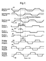
- FIG. 7 illustrates exemplary signal plots corresponding to a cycle-conduction angle of about 120 degrees. More particularly, FIG. 7 illustrates respective electromotive force (EMF) voltage signals for each phase of a three phase hybrid machine 10.
- EMF electromotive force
- FIG. 7 further illustrates signals 56, 58 and 60, such as may be generated by sensor assembly 102, each representative of a respective stream of pulses indicative of rotor position relative to each phase of the machine.
- sensor assembly 102 comprises three sensors spaced 120 or 60 electrical degrees from one another. Examples of sensors that may be used for sensing rotor position include Hall-effect sensors, magneto-resistive sensors, encoders and optical sensors. As suggested above, it will be appreciated that the sensor assembly 102 is not limited to three sensors and the spatial positioning of the sensors is not limited to 120 or 60 electrical degrees since the techniques of the present invention can be utilized with polyphase machines having more or less than three phases.
- FIG. 7 further illustrates exemplary phase currents 62, 64 and 66 that are produced by the machine when energized by stator power bridge 206 in response to control signals corresponding to the signal sequence of FIG. 7.
- the generally trapezoidal current in each phase is non-zero for a total of about 240 electrical degrees per cycle, that is, 120 degrees for positive current, and 120 degrees for negative current.
- This mode of operation generally provides relatively high machine torque per ampere.
- the timing of the energizing phase currents may be advanced by some electrical angle resulting in a greater machine torque, often refered to as phase advance or field weakening.
- the value of the phase angle to maximize torque production will vary as a function of speed.
- FIG. 1 One may note in FIG.
- the gating or control signals can be derived with straightforward logic from the signals 56, 58 and 60.
- the gating signals for the upper and lower switching devices in bridge 206, connected to generate the exemplary A-Phase current 62 would be derived from the A and C-Phase position sensors that supply the stream of pulses 56 and 60 respectively.
- such logic could be represented in Boolean logic for the A-phase upper switching device 120 as AC for generating the positive portion of the A-phase current while the gating signals for the A-phase lower switching device 122 could be represented as A C for generating the negative portion of the A-Phase current.
- logic A C allows to mask the first 60 electrical degrees of the pulse stream from the phase A sensor while logic A C allows to mask the last 60 electrical degrees of the pulse stream from the phase C sensor.
- logic for generating the respective positive portions of the B and C-Phase currents could be represented as A B and B C respectively while the logic for generating the respective negative portions of the B and C-Phase currents could be represented as A B and B C , respectively. It will be appreciated that the foregoing logic is merely illustrative being that other logical rules may be used to achieve a relative difference of about 60 electrical degrees between the cycle-conduction mode of FIG. 7 and the cycle-conduction mode discussed below in the context of FIG. 8.
- FIG. 8 illustrates exemplary machine current signals 72, 74 and 76 corresponding to a cycle-conduction angle of about 180 degrees including an exemplary optional lead angle of 30 electrical degrees relative to the zero crossing of the EMF signals.
- This mode of operation generally results in more sinusoidal phase currents and better lends itself to phase advance.
- Machines driven with 180 degree excitation generally have a lower torque per amp ratio than those with 120 degree excitation, and consequently have a higher no-load speed.
- the logic for the inverter control signals for a given phase are generally directly related to the position sensor state corresponding to that phase for 180 degree conduction. For example, when the state of the A-Phase position sensor is high, the upper switching device for phase A is energized.
- each phase current is energized approximately 30 electrical degrees after the EMF zero crossing.
- the position sensors would typically be set to trigger at the zero crossing of the phase EMF.
- phase advance or lead provided in the sinusoidal currents relative to the zero crossings of the EMF signals effectively reduces the net average value of the product of EMF voltage and current, as compared to the net average value of the product of EMF voltage and current, in the absence of any phase advance.
- the phase lead effectively introduces a current portion having a negative value and this reduces the net average value of the product of EMF voltage and current.
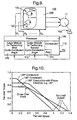
- FIG. 9 illustrates an exemplary subsystem 100 for controlling a hybrid machine 11 to selectively run under at least two different conduction angles. For example, starting the machine in a first mode of cycle-conduction (e.g., about 120 degrees) and upon the machine reaching a desired speed, switching to a second mode of cycle-conduction (e.g., about 180 degrees) that improves the no-load speed performance of the machine.
- a first mode of cycle-conduction e.g., about 120 degrees
- a second mode of cycle-conduction e.g., about 180 degrees
- subsystem 100 includes sensor assembly 102 configured to supply a respective stream of pulses indicative of rotor position relative to each phase of the machine.
- a processor 106 is configured to process each stream of pulses from the sensor assembly 102 to generate a first set of control signals.
- Stator power bridge 206 is coupled to receive the first set of control signals and energize the respective phases of the stator to start the machine.
- the first set of control signals is configured to provide a first cycle-conduction angle (e.g., about 120 electrical degrees) relative to the zero-crossings of the respective phase EMF voltages of the machine to produce a sufficiently high level of torque during start up of the machine.
- a first logic module 108 is configured to execute a first set of logical rules for selectively combining the stream of pulses from the sensor assembly 102 to provide the cycle-conduction angle based on the first set of control signals.
- the processor Upon the rotor reaching a predefined rotor speed value, such as may be determined by a comparator 112 by comparing a signal ( ⁇ r indicative of rotor speed to the predefined rotor speed value, as may be stored in a memory device 114, the processor is configured to process each stream of pulses from the sensor assembly 102 to generate a second set of control signals.
- the rotor speed may be calculated by clocking the pulse width duration of the respective stream of pulses from sensor assembly 102, without having to add any separate speed sensor component.
- the second set of control signals is configured to provide a second cycle-conduction angle (e.g., 180 electrical degrees) relative to the zero-crossings of the respective phase EMF voltages of the machine to enable a sufficiently high rotor speed and thus facilitate the occurrence of a successful cranking event for the engine of the piece of equipment.
- a second logic module 110 is configured to execute a second set of logical rules for selectively combining the stream of pulses from the sensor assembly to provide the cycle-conduction angle based on the second set of control signals.
- the cycle-conduction angle enabled by the second set of control signals exceeds the conduction angle enabled by the first set of control signals by a factor of n / n -1, wherein n is an integer number corresponding to the number of phases of the machine.
- n is not allowed to be equal to one.
- this factor is equal to 3/2 and assuming the second cycle-conduction angle is 180 degrees, the first cycle-conduction angle would correspond to 120 degrees.
- this factor is equal to 5/4 and assuming the second cycle-conduction angle is 180 degrees, the first cycle-conduction angle would correspond to 144 degrees.
- this factor is equal to two and assuming the second cycle-conduction angle is 180 degrees, the first cycle-conduction angle would correspond to 90 degrees.
- FIG 10 illustrates exemplary machine speed/torque plots as a function of cycle-conduction angle.
- the plot corresponding to 120 degree conduction has a higher torque per amp ratio than the plots corresponding to 180° degree conduction including some lead or advance angle (e.g., about 30 degrees) exhibit a higher no-load speed than both the plots corresponding to 120 degree conduction and 180 degree conduction with no phase advance.
- some lead or advance angle e.g., about 30 degrees
- the present invention is not limited to any specific phase advance value being that in some applications one may be able to quickly overcome the engine load torque thoughout the cranking speed range without having to provide any phase advance.
- a hybrid electric machine embodying aspects of the present invention may be mounted onto a vehicular engine and used to start the engine as well as generate electric power to supply vehicle electric loads and recharge the battery of the vehicle.
- a machine may be connected to the engine through a belt with an appropriate belt ratio, e.g., approximately 3:1, with a belt-tensioning device to allow for both motoring and generating modes by the machine.
- the hybrid machine and associated components such as power circuits, may be configured to allow for fast starting of a warm engine to allow engine restarts in the range of approximately 300 ms. The engine restart may be performed subsequent to shutting off the engine during an idle vehicle condition.
Landscapes
- Engineering & Computer Science (AREA)
- Power Engineering (AREA)
- Chemical & Material Sciences (AREA)
- Combustion & Propulsion (AREA)
- Mechanical Engineering (AREA)
- General Engineering & Computer Science (AREA)
- Control Of Motors That Do Not Use Commutators (AREA)
- Control Of Eletrric Generators (AREA)
Applications Claiming Priority (2)
| Application Number | Priority Date | Filing Date | Title |
|---|---|---|---|
| US10/420,348 US20040012354A1 (en) | 2001-08-13 | 2003-04-22 | Hybrid electrical machine with system and method for controlling such hybrid machine |
| US420348 | 2003-04-22 |
Publications (2)
| Publication Number | Publication Date |
|---|---|
| EP1501169A2 true EP1501169A2 (de) | 2005-01-26 |
| EP1501169A3 EP1501169A3 (de) | 2006-08-30 |
Family
ID=33489259
Family Applications (1)
| Application Number | Title | Priority Date | Filing Date |
|---|---|---|---|
| EP04076157A Withdrawn EP1501169A3 (de) | 2003-04-22 | 2004-04-15 | Elektrische Maschine in Hybridbauweise mit System und Verfahren zu ihrer Regelung |
Country Status (2)
| Country | Link |
|---|---|
| US (1) | US20040012354A1 (de) |
| EP (1) | EP1501169A3 (de) |
Cited By (3)
| Publication number | Priority date | Publication date | Assignee | Title |
|---|---|---|---|---|
| JP2014007855A (ja) * | 2012-06-25 | 2014-01-16 | Disco Abrasive Syst Ltd | ブラシレスdcモータの駆動方法 |
| CN103607080A (zh) * | 2013-12-05 | 2014-02-26 | 山东理工大学 | 切向与双径向永磁复合励磁发电机转子生产方法 |
| RU2680147C1 (ru) * | 2018-06-14 | 2019-02-18 | федеральное государственное бюджетное образовательное учреждение высшего образования "Национальный исследовательский университет "МЭИ" (ФГБОУ ВО "НИУ "МЭИ") | Способ стабилизации напряжения генератора с изменяющейся частотой вращения вала и комбинированным возбуждением |
Families Citing this family (11)
| Publication number | Priority date | Publication date | Assignee | Title |
|---|---|---|---|---|
| KR100752548B1 (ko) * | 2006-01-10 | 2007-08-29 | (주)이앤아이 | 하이브리드 전동기의 제어 장치 및 그 제어 방법 |
| WO2008120734A1 (ja) * | 2007-03-30 | 2008-10-09 | Shindengen Electric Manufacturing Co., Ltd. | ブラシレスモータ制御装置、およびブラシレスモータ制御方法 |
| US8044623B2 (en) | 2007-07-03 | 2011-10-25 | Seiko Epson Corporation | Drive control circuit for electric motor |
| KR20090084044A (ko) * | 2008-01-31 | 2009-08-05 | 엘지전자 주식회사 | 모터의 기동방법 |
| FR2975241B1 (fr) * | 2011-05-10 | 2013-05-10 | Valeo Equip Electr Moteur | Procede de commande d'une machine electrique tournante, systeme de commande et machine electrique tournante correspondants |
| US9425725B2 (en) * | 2013-02-28 | 2016-08-23 | Cirrus Logic, Inc. | Position estimation system and method for an electric motor |
| CN103607079B (zh) * | 2013-12-05 | 2015-10-07 | 山东理工大学 | 无刷电磁与双径向永磁混合励磁发电机转子生产方法 |
| US10030623B2 (en) * | 2014-12-23 | 2018-07-24 | Stmicroelectronics International N.V. | Method and system for improving the efficiency of 2-wheeled and 3-wheeled motor vehicles |
| DE102015111480A1 (de) * | 2015-07-15 | 2017-01-19 | Feaam Gmbh | Rotor und elektrische Maschine |
| JP7002619B1 (ja) * | 2020-10-20 | 2022-01-20 | 三菱電機株式会社 | 電力変換装置 |
| AU2021106784A4 (en) * | 2020-12-17 | 2021-11-18 | Rapid Power Industries | Improved brushless alternator |
Family Cites Families (29)
| Publication number | Priority date | Publication date | Assignee | Title |
|---|---|---|---|---|
| US2303893A (en) * | 1939-04-26 | 1942-12-01 | Gen Electric | Dynamo-electric machine |
| US2519895A (en) * | 1949-06-01 | 1950-08-22 | Gen Electric | Rotor for dynamoelectric machines |
| AT246275B (de) * | 1963-04-18 | 1966-04-12 | Bosch Gmbh Robert | Drehstromlichtmaschine für Fahrzeuge |
| US3303369A (en) * | 1963-12-18 | 1967-02-07 | Westinghouse Electric Corp | Dynamoelectric machines |
| DE2543196A1 (de) * | 1975-09-27 | 1977-04-07 | Bosch Gmbh Robert | Schleifringlose elektrische maschine |
| JPS5320515A (en) * | 1976-08-09 | 1978-02-24 | Hitachi Ltd | Rotor of permanent magnet synchronous motor |
| US4980595A (en) * | 1987-11-23 | 1990-12-25 | Chrysler Corporation | Multiple magnetic paths machine |
| US5130595A (en) * | 1987-11-23 | 1992-07-14 | Chrysler Corporation | Multiple magnetic paths machine |
| US5132604A (en) * | 1989-04-04 | 1992-07-21 | Honda Giken Kogyo Kabushiki Kaisha | Engine starter and electric generator system |
| US4959577A (en) * | 1989-10-23 | 1990-09-25 | General Motors Corporation | Alternating current generator |
| US5177391A (en) * | 1990-03-14 | 1993-01-05 | Nippondenso Co., Ltd. | Power generating apparatus |
| US5270604A (en) * | 1992-05-21 | 1993-12-14 | Ford Motor Company | Tandem field alternator having an improved coil and slip ring connection and method of making the same |
| JP3446313B2 (ja) * | 1993-08-30 | 2003-09-16 | 株式会社デンソー | 回転電機の回転子 |
| JPH08331784A (ja) * | 1995-03-24 | 1996-12-13 | Hitachi Metals Ltd | 永久磁石界磁方式回転機 |
| US5663605A (en) * | 1995-05-03 | 1997-09-02 | Ford Motor Company | Rotating electrical machine with electromagnetic and permanent magnet excitation |
| US5747913A (en) * | 1995-05-12 | 1998-05-05 | General Motors Corporation | Rotor for hybrid generator having improved magnet retention |
| US5552651A (en) * | 1995-07-03 | 1996-09-03 | General Motors Corporation | Alternating current generator |
| DE69615307T2 (de) * | 1995-10-19 | 2002-07-25 | Denso Corp., Kariya | Drehmaschineanlasser für Kraftfahrzeug |
| US5892313A (en) * | 1996-10-04 | 1999-04-06 | Ford Motor Company | Rotating electrical machine with permanent magnet inserts |
| DE19642784A1 (de) * | 1996-10-17 | 1998-04-23 | Bosch Gmbh Robert | Klauenpolgenerator |
| FR2787645B1 (fr) * | 1998-12-18 | 2001-03-09 | Valeo Equip Electr Moteur | Machine electrique tournante a aimants permanents et a reluctance possedant des capacites de defluxage ameliorees |
| US6066906A (en) * | 1999-02-17 | 2000-05-23 | American Superconductor Corporation | Rotating machine having superconducting windings |
| US6359366B1 (en) * | 2000-05-09 | 2002-03-19 | Ford Global Technologies, Inc. | Hybrid permanent magnet/synchronous machines |
| US6455978B1 (en) * | 2000-08-28 | 2002-09-24 | Delphi Technologies, Inc. | Hybrid twin coil electrical machine |
| US6437477B1 (en) * | 2000-08-28 | 2002-08-20 | Delphi Technologies, Inc. | Hybrid electrical machine with axial flux magnet |
| US6538358B1 (en) * | 2000-08-28 | 2003-03-25 | Delphi Technologies, Inc. | Hybrid electrical machine with axially extending magnets |
| JP3545693B2 (ja) * | 2000-11-01 | 2004-07-21 | 三菱電機株式会社 | クローポール同期機の制御方法 |
| FR2823030B1 (fr) * | 2001-01-31 | 2003-06-20 | Valeo Equip Electr Moteur | Procede de commande d'une machine electrique tournante polyphasee et reversible pour vehicule automobile a moteur thermique |
| JP3740375B2 (ja) * | 2001-02-27 | 2006-02-01 | 株式会社日立製作所 | 車両用交流発電機 |
-
2003
- 2003-04-22 US US10/420,348 patent/US20040012354A1/en not_active Abandoned
-
2004
- 2004-04-15 EP EP04076157A patent/EP1501169A3/de not_active Withdrawn
Cited By (4)
| Publication number | Priority date | Publication date | Assignee | Title |
|---|---|---|---|---|
| JP2014007855A (ja) * | 2012-06-25 | 2014-01-16 | Disco Abrasive Syst Ltd | ブラシレスdcモータの駆動方法 |
| CN103607080A (zh) * | 2013-12-05 | 2014-02-26 | 山东理工大学 | 切向与双径向永磁复合励磁发电机转子生产方法 |
| CN103607080B (zh) * | 2013-12-05 | 2015-10-07 | 山东理工大学 | 切向与双径向永磁复合励磁发电机转子生产方法 |
| RU2680147C1 (ru) * | 2018-06-14 | 2019-02-18 | федеральное государственное бюджетное образовательное учреждение высшего образования "Национальный исследовательский университет "МЭИ" (ФГБОУ ВО "НИУ "МЭИ") | Способ стабилизации напряжения генератора с изменяющейся частотой вращения вала и комбинированным возбуждением |
Also Published As
| Publication number | Publication date |
|---|---|
| US20040012354A1 (en) | 2004-01-22 |
| EP1501169A3 (de) | 2006-08-30 |
Similar Documents
| Publication | Publication Date | Title |
|---|---|---|
| US6806687B2 (en) | Vehicle motor-generator apparatus utilizing synchronous machine having field winding | |
| US6787931B2 (en) | Starter generator for internal combustion engine | |
| US6577097B2 (en) | Method and system for controlling a synchronous machine using a changeable cycle-conduction angle | |
| US8245802B2 (en) | Automotive hybrid engine assist system | |
| JP3456158B2 (ja) | 内燃機関用スタータジェネレータ | |
| CN1799192B (zh) | 用于多方式电机的脉冲宽度调制控制电路和装备有这种控制电路的多方式电机 | |
| KR100523641B1 (ko) | 차량용 발전 전동기 시스템 | |
| CN100536291C (zh) | 可变磁阻电机及将其作为发电机运行的方法 | |
| US7362002B2 (en) | Automotive starter generator apparatus | |
| CN105874189B (zh) | 发动机单元及车辆 | |
| US20040012354A1 (en) | Hybrid electrical machine with system and method for controlling such hybrid machine | |
| Chau et al. | Design and analysis of a stator-doubly-fed doubly-salient permanent-magnet machine for automotive engines | |
| CN103026614B (zh) | 永磁式交流发电机和电动机的控制器和系统 | |
| EP2139099A2 (de) | Regulierter Permanentmagnet-Hybridgenerator | |
| US20070222220A1 (en) | Aircraft engine starter/generator and controller | |
| KR20060019523A (ko) | 히트 엔진 차량용 다상의 가역 회전식 전기기기의 제어방법 | |
| JP4351792B2 (ja) | スタータを兼用したオルタネータ | |
| JP4478185B2 (ja) | 車両用エンジン始動装置 | |
| US6707184B2 (en) | Permanent magnet type AC generator having short-circuiting control circuit | |
| CN103701286B (zh) | 一种高可靠性的四相交流起动发电机 | |
| KR101322514B1 (ko) | 영구 자석 발전기의 제어기 및 제어기를 구비한 영구 자석 발전기 | |
| JP2001157497A (ja) | 同期発電機の発電制御装置 | |
| CN108631463A (zh) | 一种多边励磁永磁电机 | |
| KR100707517B1 (ko) | 자동차용 동기발전기-스타터와 같은 전기 기기의 로터필드 코일 전력의 제어를 위한 방법 및 장치 | |
| JP2876738B2 (ja) | 直並列切換回転電機 |
Legal Events
| Date | Code | Title | Description |
|---|---|---|---|
| PUAI | Public reference made under article 153(3) epc to a published international application that has entered the european phase |
Free format text: ORIGINAL CODE: 0009012 |
|
| AK | Designated contracting states |
Kind code of ref document: A2 Designated state(s): AT BE BG CH CY CZ DE DK EE ES FI FR GB GR HU IE IT LI LU MC NL PL PT RO SE SI SK TR |
|
| AX | Request for extension of the european patent |
Extension state: AL HR LT LV MK |
|
| PUAL | Search report despatched |
Free format text: ORIGINAL CODE: 0009013 |
|
| AK | Designated contracting states |
Kind code of ref document: A3 Designated state(s): AT BE BG CH CY CZ DE DK EE ES FI FR GB GR HU IE IT LI LU MC NL PL PT RO SE SI SK TR |
|
| AX | Request for extension of the european patent |
Extension state: AL HR LT LV MK |
|
| RIC1 | Information provided on ipc code assigned before grant |
Ipc: H02K 21/04 20060101ALI20060725BHEP Ipc: H02K 1/22 20060101AFI20041207BHEP |
|
| STAA | Information on the status of an ep patent application or granted ep patent |
Free format text: STATUS: THE APPLICATION IS DEEMED TO BE WITHDRAWN |
|
| 18D | Application deemed to be withdrawn |
Effective date: 20060503 |