EP1501185A2 - Méthode et dispositif pour positionner un dispositif rotatif - Google Patents
Méthode et dispositif pour positionner un dispositif rotatif Download PDFInfo
- Publication number
- EP1501185A2 EP1501185A2 EP04016385A EP04016385A EP1501185A2 EP 1501185 A2 EP1501185 A2 EP 1501185A2 EP 04016385 A EP04016385 A EP 04016385A EP 04016385 A EP04016385 A EP 04016385A EP 1501185 A2 EP1501185 A2 EP 1501185A2
- Authority
- EP
- European Patent Office
- Prior art keywords
- electric motor
- rotor
- determined
- pole
- phase
- Prior art date
- Legal status (The legal status is an assumption and is not a legal conclusion. Google has not performed a legal analysis and makes no representation as to the accuracy of the status listed.)
- Granted
Links
Images
Classifications
-
- H—ELECTRICITY
- H02—GENERATION; CONVERSION OR DISTRIBUTION OF ELECTRIC POWER
- H02P—CONTROL OR REGULATION OF ELECTRIC MOTORS, ELECTRIC GENERATORS OR DYNAMO-ELECTRIC CONVERTERS; CONTROLLING TRANSFORMERS, REACTORS OR CHOKE COILS
- H02P6/00—Arrangements for controlling synchronous motors or other dynamo-electric motors using electronic commutation dependent on the rotor position; Electronic commutators therefor
- H02P6/14—Electronic commutators
- H02P6/16—Circuit arrangements for detecting position
- H02P6/18—Circuit arrangements for detecting position without separate position detecting elements
-
- H—ELECTRICITY
- H02—GENERATION; CONVERSION OR DISTRIBUTION OF ELECTRIC POWER
- H02P—CONTROL OR REGULATION OF ELECTRIC MOTORS, ELECTRIC GENERATORS OR DYNAMO-ELECTRIC CONVERTERS; CONTROLLING TRANSFORMERS, REACTORS OR CHOKE COILS
- H02P21/00—Arrangements or methods for the control of electric machines by vector control, e.g. by control of field orientation
- H02P21/04—Arrangements or methods for the control of electric machines by vector control, e.g. by control of field orientation specially adapted for very low speeds
Definitions
- the invention relates to a method for operating a motor Positioning device according to the preamble of claim 1 as well an associated positioning device for positioning a rotatable device, in particular a tool turret.
- Position sensor used, whose output signal is the actual value for the Regulatory device provides.
- the invention is therefore based on the object, a method and a to provide associated device through which the disadvantages of State of the art are overcome.
- a method for operating a motor Positioning device can be provided by means of a sensorless positioning and a permanently reliable exact Positioning is guaranteed with high positioning speed.
- the associated positioning device should have a high level of operational safety at high positioning speed and high Provide positioning accuracy.
- This object is in a method for operating a motor Positioning device with a rotor and a stator having electric motor with at least one pole pair and a Control device for the electric motor achieved in that the strand currents and / or phase voltages of the electric motor are measured and the sensorless position determination of the rotor can be used that below a predeterminable minimum speed a pole jump through Evaluating the measured strand sizes is determined and that a determined pole jump by readjustment of the electric motor automatically is compensated.
- Position estimator can be used, as he e.g. from the publication Chen Z. et al .: "New Adaptive Sliding Observer for Sensorless Control of Surface Permanent Magnet Synchronous Motor "IEEE Transactions on Industrial Electronics, Vol. 47, no. 3, 2000, pages 582-591.
- position estimators only work from about 10% of Rated speed of the electric motor with sufficient accuracy and Reliability. Below this speed value, for example due to the occurring signal noise to signal distortions and thus come to measurement inaccuracies.
- a positioning device As they in particular for the drive of a tool turret or a Rotary indexing table is used, this lower speed range However drive through relatively often, especially in Acceleration and deceleration from or into a state of rest, in which the specified position is maintained. Due to the required high Positioning speeds can be especially when braking the electric motor for skipping a pole of the rotor relative to the Stator come, which - if this is not corrected - to one actual malposition of the rotor and thus the connected leads to be positioned rotating device. Because of this, the sensorless position determination in generic Positioning devices in contrast to the speed control so far still no entrance found.
- the electric motor is preferably a Synchronous motor, for example, an external rotor, in which on the bell-shaped external rotor with alternating polarity Permanent magnets are applied, in particular glued. Accordingly, the invention is also a permanent-magnet Internal rotor applicable.
- the pole pair number is generally n ⁇ 1, preferably n ⁇ 3. This allows for a complete 360 ° Rotation of the rotor around the stator total 2xn stable positions of the stator Rotor be taken with respect to the stator. A complete one Rotation of the rotor of 360 ° correspond to so-called n electrical revolutions.
- the electric motor as permanent magnet synchronous motor designed.
- the invention of a three-phase synchronous machine is preferably by a converter or inverter with supplied electrical energy.
- the inverter Given strand voltages, whereupon the inverter strand currents in feeds the electric motor.
- the phase currents are measured and evaluated with regard to the occurrence of pole jumps. at corresponding design of the inverter, it would also be conceivable Strangbonden as measures for determining the occurrence of Pole jumps to pull.
- the pole jumps are determined in a pole jump detection unit the control device of the positioning device.
- the control device of the positioning device For this purpose, either the directly measured phase currents used, or preferably in a two-phase Reference system transformed values of the measured phase currents, in particular, in a corresponding rotorfestes reference system transformed values.
- the pole jump detection unit supplied the manipulated variables of the control device, in particular those in a two-phase and preferably rotorfestes Reference system transformed values of the manipulated variables.
- the rotatable device to be positioned is a tool turret or a so-called rotary indexing table.
- a detachable locking device for example a so-called Hirth toothing, may be arranged for clamping the position of the rotatable device.
- Hirth toothing By this locking device very high clamping forces can be applied, which ensures a secure clamping of the device even when high external forces and torques occur.
- the clamping torques are greater than the drive torques of the motor, based on the axis of rotation of the rotatable device to be positioned.
- the electric motor is already before loosening the Locking device and / or until the activation of the locking device energized. This ensures that the motor Positioning device set position of the rotatable device also defined to the locking device is passed or by the Locking device clamped position to the positioning device is handed over.
- At least one starting value for the actual, absolute angular position of the rotatable device is determined by a referencing process. Referencing can be done, for example, by approaching a predetermined reference point, by external "teach-in", or the like.
- the invention also relates to an associated positioning device, whose control device has a pole shift detection unit, by means of the below a predetermined minimum speed, a pole shift of the rotor by evaluating the measured phase currents and / or phase voltages can be determined and by readjusting the electric motor automatically is compensable.
- the readjustment of the electric motor can be the simplest Fall also be a caster or follow-up. Basically the readjustment but also during the actual Positioning process be made.
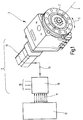
- Fig. 1 shows a positioning device 1 according to the invention, which positions a rotatable receiving disk 2 of a tool turret 3, as used for example in a machine tool.
- different tool disks can be screwed to the receiving disk 2, on which the tool holders are fastened axially or radially.
- the tools can in turn be driven in rotation.
- the receiving disk 2 is rotatable about the axis 4 in the direction of the double arrow 5. By turning the receiving disk 2, the tools are engageable with the workpiece (not shown).
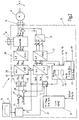
- the positioning device 1 has a Regulating device 10, which via an interface 11 with a Machine control 12 is connected. On the output side is the Control device 10 via an example three-phase connection line 13 connected to the electric motor 14. In addition, the Control device 10 via a terminal 15 to an electrical Power grid.
- the electric motor 14 is a three-phase permanent magnet synchronous machine with the engine speed N and the actual rotor position angle ⁇ .
- the phase currents i a , i b and i c are used as measured variables.
- the strand voltages could be used as measured variables instead of the strand currents.
- phase currents i a , i b are still determined within the control device 10 by measurement.
- the above condition applies to a delta connection and also to a star connection of the three-phase synchronous machine, in any case when the neutral point is not additionally electrically connected.
- phase currents i a, i b, i c are converted into the first transformation unit 22 into an equivalent two-phase system, the resulting therefrom sizes i ⁇ m, and ⁇ i, m represent the real and imaginary part. This is still a stator-fixed two-phase system.
- a second transformation unit 23 the quantities i ⁇ , m and i ⁇ , m are transformed according to a Clarke / Park transformation into the corresponding quantities i d, m and i q, m of a rotor-fixed two-phase system.
- I d, m is the real part of the equivalent measured phase current and i q, m is the imaginary part of the equivalent measured phase current.
- the values i d, m , i q, m of the rotor-fixed two-phase system are then combined with the setpoint specifications i d, soll , i q, the position control 24 in corresponding adders 25, 26.
- the position control 24 is preferably a controller with a proportional / integral (PI) characteristic, which receives a desired position of the machine controller 12 via the interface 11.
- the engine controller 12 merely advises to travel from a position A to a position B. This should be done as quickly as possible, with the machine control 12 can specify the simplified ramp shown in FIG. 2 or a bit pattern, but this need not. According to the present invention, in particular when starting from the position control 24 only a desired value i q, soll should be specified, which corresponds to the maximum permissible value for the electric motor 14.
- the control device 10 can in a first Time period of the positioning process, in particular during Accelerate, register which acceleration values with regard to the load to be driven by the electric motor 14 is possible.
- the output signals of the first and second adders 25, 26 are respectively applied to a first and a second further regulator 27, 28 which in the illustrated embodiment each have a proportional / integral (PI) characteristic.
- PI proportional / integral
- the values u d , u q are transformed by the third transformation unit 29 into equivalent values of the stator-fixed two-phase system with the real part u ⁇ and the imaginary part u ⁇ .
- the third transformation unit 29 executes a transformation that is inverse to the Clarke / Park transformation of the second transformation unit 23.
- the fourth transformation unit 30 transforms the values u ⁇ , u ⁇ into control voltage values u a , u b , u c for the three phases of the electric motor 14, which in turn serve as input variables for the converter or inverter 31.
- the fourth transformation unit 30 executes a transformation that is inverse to the transformation of the first transformation unit 22.
- the first transformation unit 22 is an essentially trigonometric conversion in the stator-fixed three-phase system from the phase currents i a , i b , i c of the electric motor 14 into the equivalent quantities of the two-phase system i ⁇ , m and i ⁇ , m .
- the fourth transformation unit 30 is an essentially trigonometric conversion in the stator-fixed three-phase system from the equivalent control voltages u ⁇ , u ⁇ into the control voltage values u a , u b , u c for the three phases of the electric motor 14.
- the inverter 31 is connected via the terminal 15 with electrical energy supplied and has the output side, the connection line 13 for the Electric motor 14 on.
- the position of the electric motor 14 is determined in each case by a position estimation unit 40.
- This position estimation unit 40 will refer to the the measured phase quantities equivalent values ⁇ i m, i and ⁇ , the control voltage of the stator-m two-phase system is supplied as the set values ⁇ and ⁇ and u fixed to the stator of the two-phase system. From this, the position estimation unit 40 determines the estimated rotor attitude angle ⁇ ', which is supplied to both the attitude control 24 and the second and third transformation units 23, 29.
- a superposed controller 41 which estimates not only the angular position from the given values u ⁇ and u ⁇ and the actual values i ⁇ , m and i ⁇ , m , but from the given values u ⁇ and u ⁇ assumable values i ⁇ , m 'and i ⁇ , m' forms and these, m with the actual values i ⁇ and i ⁇ , m and compares the actual rotor speed N and the rotor position angle ⁇ is calculated from this comparison. It is advantageous that as a result no values have to be assumed for the rotor speed N required for estimating the angular position, and a corresponding error source is excluded.
- a carrier signal 45 is superimposed, for example, the form cos ⁇ t, wherein the rotational frequency ⁇ is not necessarily related to the rotational speed N of the electric motor 14.
- the carrier signal 45 serves for magnetic excitation of the electric motor 14 in order to be able to detect a standstill.
- the carrier signal 45 can be superimposed permanently or only in the region below the minimum rotational speed N min .
- an auxiliary carrier signal 46 corresponding to the carrier signal 45 is connected to an evaluation unit 47, which is affiliated with the position estimation unit 40 or integrated into it.
- the evaluation unit 47 determines a determined rotor position angle ⁇ * using the real part i d, m and the imaginary part i q, m of the rotor-fixed two-phase system.
- the present invention generates the carrier signal 45 as a response signal of the electric motor 14, a current i d, m , i q, m , which is demodulated with the evaluation unit 47 using the subcarrier signal 46.
- a readjustment unit 48 preferably integrated in the position estimation unit 40, the difference between the estimated rotor position angle ⁇ 'and the rotor position angle ⁇ * determined by the evaluation unit 47 is formed, which as a rule indicates the malposition of the rotor. This difference is preferably used only internally in the control device 10 or even only in the position estimation unit 40 and should also be regulated to zero below the predetermined minimum speed N min .
- the readjustment unit 48 of the electric motor 14 is driven so that the estimated rotor position angle ⁇ 'corresponds to the actual rotor position angle ⁇ .
- the position control 24 can also switch over the control line 42 the switch 43 from the position estimation unit 40 to the pole jump detection unit 44, which then the position specification and thus the determination of the estimated rotor position angle ⁇ 'for the position control 24 and the second and third transformation unit 23, 29 takes over.
- the pole jump detection unit 44 is supplied with the values of the rotor-fixed two-phase system i d, m and i q, m which are equivalent to the measured phase currents i a , i b .
- a model for the electric motor 14 is implemented, by means of which the associated control voltage values u d ', u q ' of the rotor-fixed two-phase system are calculated from the values i d, m and i q, m .
- the calculated values u d ', u q ' are compared with the actual values u d , u q .
- the comparison signal determined in this way is compared with a predefinable threshold value, and if this is exceeded, the peaks resulting in the course of the comparison signal are counted and considered to be representative of the occurrence of pole jumps. A pole shift is therefore always recognized as such when, with a preceding relative minimum, a subsequent relative maximum is achieved in the course of the comparison signal.
- the square of the magnitude of the vector with the components u d 'and u q ' and the square of the magnitude of the vector with the components u d and u q are formed.
- the difference of these two squares of the amounts is formed and this difference signal is fed to a low-pass filter.
- pole jumps characteristic peaks in the waveform after the low pass, resulting from the sudden exceeding of the pole boundary. These tips are, for. B. is detected by comparison with a threshold value, and if this is exceeded, resulting in the course of the low-pass filtered difference signal peaks are counted and considered representative of the occurrence of pole jumps. Each peak corresponds to the angle of rotation of a magnetic pole.
- the pole jumps thus determined are added up.
- the correction corresponds to the number multiplied by the counted peaks of the low pass filtered difference signal with the angle of rotation of a magnetic pole.
- the pole jump detection unit 44 may alternatively or in addition to the Evaluation unit 47 of the position estimation unit 40 may be provided. in the In case of a supplement, the pole jump recognition unit 44 For example, to control the function of the evaluation 47th be provided.
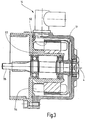
- FIG. 3 shows a cross section through the electric motor 14 of FIG Positioning device according to the invention 1.
- a total of 28 Permanent magnets 52 glued in alternating polarity, so that a total number of pole pairs of 28: 2 14 results.
- the electric motor 14 has, for example, a rated power between 0.5 and 10 kW, in particular between 2 and 5 kWh and preferably about 3.5 kW.
- the nominal speed depends on the number of pole pairs of the Motors, the magnetic reversal losses of the engine and the Computing power of the control device 10.
- the rated speed is here for example, about 4000 rpm.
- Positioning device 1 for a tool turret 3 or for a so-called rotary indexing table is a translation of the speed of the Electric motor 14 with a transmission, in particular a Planetary gear.
- the gear ratio is between 8: 1 and 240: 1, especially between 24: 1 and 144: 1.
- the positioning device 1 serves only the setting of desired position of the tool turret 3. Once this position is achieved, the tool turret 3 by a detachable Clamping device in its set by the electric motor 14 Position fixed.
- the tool change is initiated.
- the first Electric motor 14 energized.
- the locking device for mechanically fixing the Position of the tool turret 3 solved.
- a repositioning of the tool turret 3 after the inventive method Preferably, it is considered soluble Locking device used a Hirth toothing.
Landscapes
- Engineering & Computer Science (AREA)
- Power Engineering (AREA)
- Control Of Motors That Do Not Use Commutators (AREA)
- Automobile Manufacture Line, Endless Track Vehicle, Trailer (AREA)
- Control Of Ac Motors In General (AREA)
Priority Applications (1)
| Application Number | Priority Date | Filing Date | Title |
|---|---|---|---|
| EP08022001A EP2037568B1 (fr) | 2003-07-15 | 2004-07-13 | Procédé de fonctionnement d'un dispositif de positionnement motorisé ainsi que dispositif de positionnement correspondant |
Applications Claiming Priority (2)
| Application Number | Priority Date | Filing Date | Title |
|---|---|---|---|
| DE10333414 | 2003-07-15 | ||
| DE10333414A DE10333414A1 (de) | 2003-07-15 | 2003-07-15 | Verfahren zum Betrieb einer motorischen Positionierungsvorrichtung sowie zugehörige Positionierungsvorrichtung |
Related Child Applications (1)
| Application Number | Title | Priority Date | Filing Date |
|---|---|---|---|
| EP08022001A Division EP2037568B1 (fr) | 2003-07-15 | 2004-07-13 | Procédé de fonctionnement d'un dispositif de positionnement motorisé ainsi que dispositif de positionnement correspondant |
Publications (3)
| Publication Number | Publication Date |
|---|---|
| EP1501185A2 true EP1501185A2 (fr) | 2005-01-26 |
| EP1501185A3 EP1501185A3 (fr) | 2006-07-12 |
| EP1501185B1 EP1501185B1 (fr) | 2009-09-09 |
Family
ID=33483025
Family Applications (2)
| Application Number | Title | Priority Date | Filing Date |
|---|---|---|---|
| EP08022001A Expired - Lifetime EP2037568B1 (fr) | 2003-07-15 | 2004-07-13 | Procédé de fonctionnement d'un dispositif de positionnement motorisé ainsi que dispositif de positionnement correspondant |
| EP04016385A Expired - Lifetime EP1501185B1 (fr) | 2003-07-15 | 2004-07-13 | Méthode et dispositif pour positionner un dispositif rotatif |
Family Applications Before (1)
| Application Number | Title | Priority Date | Filing Date |
|---|---|---|---|
| EP08022001A Expired - Lifetime EP2037568B1 (fr) | 2003-07-15 | 2004-07-13 | Procédé de fonctionnement d'un dispositif de positionnement motorisé ainsi que dispositif de positionnement correspondant |
Country Status (3)
| Country | Link |
|---|---|
| EP (2) | EP2037568B1 (fr) |
| AT (2) | ATE442699T1 (fr) |
| DE (3) | DE10333414A1 (fr) |
Cited By (6)
| Publication number | Priority date | Publication date | Assignee | Title |
|---|---|---|---|---|
| DE102006061310A1 (de) * | 2006-12-22 | 2008-07-03 | Tünkers Maschinenbau Gmbh | Vorrichtung zum Bewegen von Massen mittels einer Welle, die über einen motorischen Antrieb, ggf. mit unterschiedlichen Winkelgeschwindigkeiten antreibbar ist, und Verwendung einer derartigen Vorrichtung bei einem Drehtisch mit Schrittantrieb |
| EP2093642A1 (fr) | 2008-02-25 | 2009-08-26 | TÜNKERS MASCHINENBAU GmbH | Dispositif de déplacement de masses à l'aide d'un cylindre d'entraînement, entraîné à l'aide d'un entraînement motorisé, ainsi que commande ou régulation pour un tel dispositif et utilisation d'un dispositif destiné au déplacement de masses avec une table rotative commandée pas-à-pas |
| EP1843461A3 (fr) * | 2006-04-07 | 2010-01-13 | Sanyo Electric Co., Ltd. | Dispositif de régulation d'un moteur |
| FR2969416A1 (fr) * | 2010-12-21 | 2012-06-22 | Francecol Technology | Procede et dispositif permettant de determiner la position du rotor d'une machine electrique. |
| EP3001271A1 (fr) * | 2014-09-24 | 2016-03-30 | Siemens Aktiengesellschaft | Procédé et dispositif destinés à la quantité de mouvement d'un entraînement |
| CN117574991A (zh) * | 2024-01-15 | 2024-02-20 | 武汉大学 | 基于ga算法优化bp神经网络的极移预报方法及系统 |
Families Citing this family (3)
| Publication number | Priority date | Publication date | Assignee | Title |
|---|---|---|---|---|
| DE102007035030A1 (de) | 2007-07-26 | 2009-01-29 | Sauter Feinmechanik Gmbh | Werkzeugrevolvereinheit für eine Werkzeugmaschine |
| DE102008045182B4 (de) | 2008-08-30 | 2010-09-23 | Sauter Feinmechanik Gmbh | Werkzeughaltevorrichtung für eine Werkzeugmaschine |
| CN103684187B (zh) * | 2013-12-31 | 2016-09-21 | 清华大学 | 一种永磁同步电机Id=0电流控制算法 |
Family Cites Families (8)
| Publication number | Priority date | Publication date | Assignee | Title |
|---|---|---|---|---|
| DE4302344A1 (de) * | 1993-01-28 | 1994-08-04 | Bosch Gmbh Robert | Verfahren und Vorrichtung zur Steuerung einer Antriebseinheit eines Fahrzeugs |
| JP2906926B2 (ja) * | 1993-07-07 | 1999-06-21 | 三菱電機株式会社 | ブラシレスモータの制御装置 |
| JP3797508B2 (ja) * | 1997-06-24 | 2006-07-19 | 株式会社安川電機 | 永久磁石型同期電動機のセンサレス速度制御方法及びその脱調検出方法 |
| JP3815584B2 (ja) * | 1997-08-01 | 2006-08-30 | 株式会社安川電機 | センサレス同期モータの駆動装置 |
| DE19751375A1 (de) * | 1997-11-20 | 1999-05-27 | Christian Dipl Ing Obermeier | Verfahren zur Rekonstruktion von Lastkräften bzw. Lastmomenten sowie Beschleunigungen bei elektrischen Antrieben aus den Informationen der Klemmengrößen im geschlossenen Drehzahl- oder Lageregelkreis |
| JP3867518B2 (ja) * | 2001-06-06 | 2007-01-10 | 株式会社日立製作所 | 同期電動機のセンサレス制御システム |
| JP3680016B2 (ja) | 2001-09-03 | 2005-08-10 | 三菱電機株式会社 | 同期電動機の脱調検出装置 |
| JP2003134880A (ja) | 2001-10-19 | 2003-05-09 | Matsushita Electric Ind Co Ltd | ディスク装置とモータ |
-
2003
- 2003-07-15 DE DE10333414A patent/DE10333414A1/de not_active Withdrawn
-
2004
- 2004-07-13 EP EP08022001A patent/EP2037568B1/fr not_active Expired - Lifetime
- 2004-07-13 DE DE502004010026T patent/DE502004010026D1/de not_active Expired - Lifetime
- 2004-07-13 AT AT04016385T patent/ATE442699T1/de not_active IP Right Cessation
- 2004-07-13 EP EP04016385A patent/EP1501185B1/fr not_active Expired - Lifetime
- 2004-07-13 DE DE502004010951T patent/DE502004010951D1/de not_active Expired - Lifetime
- 2004-07-13 AT AT08022001T patent/ATE462221T1/de not_active IP Right Cessation
Cited By (10)
| Publication number | Priority date | Publication date | Assignee | Title |
|---|---|---|---|---|
| EP1843461A3 (fr) * | 2006-04-07 | 2010-01-13 | Sanyo Electric Co., Ltd. | Dispositif de régulation d'un moteur |
| US7893639B2 (en) | 2006-04-07 | 2011-02-22 | Sanyo Electric Co., Ltd. | Motor control device |
| DE102006061310A1 (de) * | 2006-12-22 | 2008-07-03 | Tünkers Maschinenbau Gmbh | Vorrichtung zum Bewegen von Massen mittels einer Welle, die über einen motorischen Antrieb, ggf. mit unterschiedlichen Winkelgeschwindigkeiten antreibbar ist, und Verwendung einer derartigen Vorrichtung bei einem Drehtisch mit Schrittantrieb |
| DE102006061310B4 (de) * | 2006-12-22 | 2011-05-26 | Tünkers Maschinenbau Gmbh | Vorrichtung zum Bewegen von Massen mittels einer Welle oder Walze, die über einen motorischen Antrieb antreibbar ist |
| EP2093642A1 (fr) | 2008-02-25 | 2009-08-26 | TÜNKERS MASCHINENBAU GmbH | Dispositif de déplacement de masses à l'aide d'un cylindre d'entraînement, entraîné à l'aide d'un entraînement motorisé, ainsi que commande ou régulation pour un tel dispositif et utilisation d'un dispositif destiné au déplacement de masses avec une table rotative commandée pas-à-pas |
| FR2969416A1 (fr) * | 2010-12-21 | 2012-06-22 | Francecol Technology | Procede et dispositif permettant de determiner la position du rotor d'une machine electrique. |
| WO2012085412A3 (fr) * | 2010-12-21 | 2013-08-08 | Sintertech | Procédé et dispositif permettant de déterminer la position du rotor d'une machine électrique |
| EP3001271A1 (fr) * | 2014-09-24 | 2016-03-30 | Siemens Aktiengesellschaft | Procédé et dispositif destinés à la quantité de mouvement d'un entraînement |
| CN117574991A (zh) * | 2024-01-15 | 2024-02-20 | 武汉大学 | 基于ga算法优化bp神经网络的极移预报方法及系统 |
| CN117574991B (zh) * | 2024-01-15 | 2024-04-02 | 武汉大学 | 基于ga算法优化bp神经网络的极移预报方法及系统 |
Also Published As
| Publication number | Publication date |
|---|---|
| DE502004010951D1 (de) | 2010-05-06 |
| EP2037568A1 (fr) | 2009-03-18 |
| EP1501185A3 (fr) | 2006-07-12 |
| ATE442699T1 (de) | 2009-09-15 |
| EP2037568B1 (fr) | 2010-03-24 |
| EP1501185B1 (fr) | 2009-09-09 |
| DE10333414A1 (de) | 2005-02-10 |
| DE502004010026D1 (de) | 2009-10-22 |
| ATE462221T1 (de) | 2010-04-15 |
Similar Documents
| Publication | Publication Date | Title |
|---|---|---|
| EP2194641B1 (fr) | Système de détermination de la position initiale des pôles du rotor d'un moteur électrique | |
| EP3134964B1 (fr) | Procede et dispositif pour reduire l'ondulation de couple dans un moteur a courant continu | |
| DE102008021425A1 (de) | Verfahren und System zur Ausrichtung eines Resolvers in einem Elektromotorsystem | |
| DE102008001408A1 (de) | Offsetwinkelbestimmung bei Synchronmaschinen | |
| DE102013019852B4 (de) | Detektor für eine Magnetpolposition in einem Synchronmotor | |
| DE102016103470A1 (de) | Verfahren zum Betreiben einer elektrischen Maschine | |
| EP0065614A1 (fr) | Servomoteur à réaction rapide | |
| EP1501185B1 (fr) | Méthode et dispositif pour positionner un dispositif rotatif | |
| DE102004037584A1 (de) | Antriebseinheit | |
| EP1699676B1 (fr) | Procede de ralentissement d'un moteur electrique et mecanisme d'entrainement electrique | |
| WO2018072778A1 (fr) | Procédé de correction des erreurs de mesure d'un capteur de rotation sinus-consinus | |
| EP2555417B1 (fr) | Détermination de l'angle d'un rotor d'un moteur électrique dans un véhicule équipé de capteurs de roue | |
| EP2982035B1 (fr) | Procédé de mise en marche d'un moteur électrique à vitesse variable | |
| DE102014211881A1 (de) | Verfahren zur Überprüfung einer Lage eines Rotors einer elektrischen Maschine | |
| DE19928481A1 (de) | Verfahren zur vereinfachten feldorientierten Regelung von Asynchronmaschinen | |
| EP3046250B1 (fr) | Procède de surveillance de couple et convertisseur | |
| EP4016835A1 (fr) | Procédé de détermination de la position angulaire du rotor d'un moteur synchrone alimenté par un inverseur et dispositif de mise en oeuvre du procédé | |
| WO2018095482A1 (fr) | Procédé et agencement de circuit pour déterminer la position d'un rotor d'un moteur électrique | |
| DE102013201241A1 (de) | Verfahren und Einrichtung zur Bestimmung der Position des Rotors bei einem bürstenlosen Gleichstrommotor | |
| EP3098960B1 (fr) | Procede destine au fonctionnement d'une machine electrique et entrainement | |
| DE102020201087A1 (de) | Verfahren und Vorrichtung zum Betreiben einer Elektromaschine, Antriebseinrichtung | |
| EP3659253B1 (fr) | Procédé de fonctionnement d'un moteur à réluctance synchrone et système d'entraînement l'utilisant | |
| DE102009029396A1 (de) | Verfahren zum Betreiben einer elektrischen Maschine sowie elektrische Maschine | |
| DE102009020505B4 (de) | Verfahren zum Betreiben eines Elektromotors und Antrieb | |
| EP4645676A1 (fr) | Procédé de fonctionnement d'un moteur à courant continu sans balai, agencement pour la mise en uvre du procédé et véhicule |
Legal Events
| Date | Code | Title | Description |
|---|---|---|---|
| PUAI | Public reference made under article 153(3) epc to a published international application that has entered the european phase |
Free format text: ORIGINAL CODE: 0009012 |
|
| AK | Designated contracting states |
Kind code of ref document: A2 Designated state(s): AT BE BG CH CY CZ DE DK EE ES FI FR GB GR HU IE IT LI LU MC NL PL PT RO SE SI SK TR |
|
| AX | Request for extension of the european patent |
Extension state: AL HR LT LV MK |
|
| PUAL | Search report despatched |
Free format text: ORIGINAL CODE: 0009013 |
|
| AK | Designated contracting states |
Kind code of ref document: A3 Designated state(s): AT BE BG CH CY CZ DE DK EE ES FI FR GB GR HU IE IT LI LU MC NL PL PT RO SE SI SK TR |
|
| AX | Request for extension of the european patent |
Extension state: AL HR LT LV MK |
|
| RIC1 | Information provided on ipc code assigned before grant |
Ipc: H02P 6/18 20060101AFI20041206BHEP |
|
| 17P | Request for examination filed |
Effective date: 20061002 |
|
| AKX | Designation fees paid |
Designated state(s): AT BE BG CH CY CZ DE DK EE ES FI FR GB GR HU IE IT LI LU MC NL PL PT RO SE SI SK TR |
|
| 17Q | First examination report despatched |
Effective date: 20080207 |
|
| GRAP | Despatch of communication of intention to grant a patent |
Free format text: ORIGINAL CODE: EPIDOSNIGR1 |
|
| RTI1 | Title (correction) |
Free format text: METHOD AND ARRANGEMENT FOR POSITIONING A ROTATING DEVICE |
|
| GRAS | Grant fee paid |
Free format text: ORIGINAL CODE: EPIDOSNIGR3 |
|
| GRAA | (expected) grant |
Free format text: ORIGINAL CODE: 0009210 |
|
| AK | Designated contracting states |
Kind code of ref document: B1 Designated state(s): AT BE BG CH CY CZ DE DK EE ES FI FR GB GR HU IE IT LI LU MC NL PL PT RO SE SI SK TR |
|
| REG | Reference to a national code |
Ref country code: GB Ref legal event code: FG4D Free format text: NOT ENGLISH |
|
| REG | Reference to a national code |
Ref country code: CH Ref legal event code: EP |
|
| REG | Reference to a national code |
Ref country code: IE Ref legal event code: FG4D |
|
| REF | Corresponds to: |
Ref document number: 502004010026 Country of ref document: DE Date of ref document: 20091022 Kind code of ref document: P |
|
| PG25 | Lapsed in a contracting state [announced via postgrant information from national office to epo] |
Ref country code: SE Free format text: LAPSE BECAUSE OF FAILURE TO SUBMIT A TRANSLATION OF THE DESCRIPTION OR TO PAY THE FEE WITHIN THE PRESCRIBED TIME-LIMIT Effective date: 20090909 Ref country code: FI Free format text: LAPSE BECAUSE OF FAILURE TO SUBMIT A TRANSLATION OF THE DESCRIPTION OR TO PAY THE FEE WITHIN THE PRESCRIBED TIME-LIMIT Effective date: 20090909 |
|
| NLV1 | Nl: lapsed or annulled due to failure to fulfill the requirements of art. 29p and 29m of the patents act | ||
| PG25 | Lapsed in a contracting state [announced via postgrant information from national office to epo] |
Ref country code: PL Free format text: LAPSE BECAUSE OF FAILURE TO SUBMIT A TRANSLATION OF THE DESCRIPTION OR TO PAY THE FEE WITHIN THE PRESCRIBED TIME-LIMIT Effective date: 20090909 Ref country code: NL Free format text: LAPSE BECAUSE OF FAILURE TO SUBMIT A TRANSLATION OF THE DESCRIPTION OR TO PAY THE FEE WITHIN THE PRESCRIBED TIME-LIMIT Effective date: 20090909 Ref country code: SI Free format text: LAPSE BECAUSE OF FAILURE TO SUBMIT A TRANSLATION OF THE DESCRIPTION OR TO PAY THE FEE WITHIN THE PRESCRIBED TIME-LIMIT Effective date: 20090909 |
|
| PG25 | Lapsed in a contracting state [announced via postgrant information from national office to epo] |
Ref country code: CY Free format text: LAPSE BECAUSE OF FAILURE TO SUBMIT A TRANSLATION OF THE DESCRIPTION OR TO PAY THE FEE WITHIN THE PRESCRIBED TIME-LIMIT Effective date: 20090909 |
|
| REG | Reference to a national code |
Ref country code: IE Ref legal event code: FD4D |
|
| PG25 | Lapsed in a contracting state [announced via postgrant information from national office to epo] |
Ref country code: PT Free format text: LAPSE BECAUSE OF FAILURE TO SUBMIT A TRANSLATION OF THE DESCRIPTION OR TO PAY THE FEE WITHIN THE PRESCRIBED TIME-LIMIT Effective date: 20100111 Ref country code: EE Free format text: LAPSE BECAUSE OF FAILURE TO SUBMIT A TRANSLATION OF THE DESCRIPTION OR TO PAY THE FEE WITHIN THE PRESCRIBED TIME-LIMIT Effective date: 20090909 Ref country code: RO Free format text: LAPSE BECAUSE OF FAILURE TO SUBMIT A TRANSLATION OF THE DESCRIPTION OR TO PAY THE FEE WITHIN THE PRESCRIBED TIME-LIMIT Effective date: 20090909 Ref country code: CZ Free format text: LAPSE BECAUSE OF FAILURE TO SUBMIT A TRANSLATION OF THE DESCRIPTION OR TO PAY THE FEE WITHIN THE PRESCRIBED TIME-LIMIT Effective date: 20090909 Ref country code: ES Free format text: LAPSE BECAUSE OF FAILURE TO SUBMIT A TRANSLATION OF THE DESCRIPTION OR TO PAY THE FEE WITHIN THE PRESCRIBED TIME-LIMIT Effective date: 20091220 Ref country code: IE Free format text: LAPSE BECAUSE OF FAILURE TO SUBMIT A TRANSLATION OF THE DESCRIPTION OR TO PAY THE FEE WITHIN THE PRESCRIBED TIME-LIMIT Effective date: 20090909 |
|
| PG25 | Lapsed in a contracting state [announced via postgrant information from national office to epo] |
Ref country code: SK Free format text: LAPSE BECAUSE OF FAILURE TO SUBMIT A TRANSLATION OF THE DESCRIPTION OR TO PAY THE FEE WITHIN THE PRESCRIBED TIME-LIMIT Effective date: 20090909 |
|
| PLBE | No opposition filed within time limit |
Free format text: ORIGINAL CODE: 0009261 |
|
| STAA | Information on the status of an ep patent application or granted ep patent |
Free format text: STATUS: NO OPPOSITION FILED WITHIN TIME LIMIT |
|
| PG25 | Lapsed in a contracting state [announced via postgrant information from national office to epo] |
Ref country code: DK Free format text: LAPSE BECAUSE OF FAILURE TO SUBMIT A TRANSLATION OF THE DESCRIPTION OR TO PAY THE FEE WITHIN THE PRESCRIBED TIME-LIMIT Effective date: 20090909 |
|
| 26N | No opposition filed |
Effective date: 20100610 |
|
| PG25 | Lapsed in a contracting state [announced via postgrant information from national office to epo] |
Ref country code: GR Free format text: LAPSE BECAUSE OF FAILURE TO SUBMIT A TRANSLATION OF THE DESCRIPTION OR TO PAY THE FEE WITHIN THE PRESCRIBED TIME-LIMIT Effective date: 20091210 |
|
| BERE | Be: lapsed |
Owner name: SAUTER FEINMECHANIK G.M.B.H. Effective date: 20100731 |
|
| PG25 | Lapsed in a contracting state [announced via postgrant information from national office to epo] |
Ref country code: MC Free format text: LAPSE BECAUSE OF NON-PAYMENT OF DUE FEES Effective date: 20100731 |
|
| REG | Reference to a national code |
Ref country code: CH Ref legal event code: PL |
|
| PG25 | Lapsed in a contracting state [announced via postgrant information from national office to epo] |
Ref country code: LI Free format text: LAPSE BECAUSE OF NON-PAYMENT OF DUE FEES Effective date: 20100731 Ref country code: CH Free format text: LAPSE BECAUSE OF NON-PAYMENT OF DUE FEES Effective date: 20100731 |
|
| PG25 | Lapsed in a contracting state [announced via postgrant information from national office to epo] |
Ref country code: BE Free format text: LAPSE BECAUSE OF NON-PAYMENT OF DUE FEES Effective date: 20100731 |
|
| PG25 | Lapsed in a contracting state [announced via postgrant information from national office to epo] |
Ref country code: AT Free format text: LAPSE BECAUSE OF NON-PAYMENT OF DUE FEES Effective date: 20100713 |
|
| PG25 | Lapsed in a contracting state [announced via postgrant information from national office to epo] |
Ref country code: HU Free format text: LAPSE BECAUSE OF FAILURE TO SUBMIT A TRANSLATION OF THE DESCRIPTION OR TO PAY THE FEE WITHIN THE PRESCRIBED TIME-LIMIT Effective date: 20100310 Ref country code: BG Free format text: LAPSE BECAUSE OF FAILURE TO SUBMIT A TRANSLATION OF THE DESCRIPTION OR TO PAY THE FEE WITHIN THE PRESCRIBED TIME-LIMIT Effective date: 20090909 Ref country code: LU Free format text: LAPSE BECAUSE OF NON-PAYMENT OF DUE FEES Effective date: 20100713 |
|
| PG25 | Lapsed in a contracting state [announced via postgrant information from national office to epo] |
Ref country code: TR Free format text: LAPSE BECAUSE OF FAILURE TO SUBMIT A TRANSLATION OF THE DESCRIPTION OR TO PAY THE FEE WITHIN THE PRESCRIBED TIME-LIMIT Effective date: 20090909 |
|
| PGFP | Annual fee paid to national office [announced via postgrant information from national office to epo] |
Ref country code: GB Payment date: 20130508 Year of fee payment: 10 |
|
| PGFP | Annual fee paid to national office [announced via postgrant information from national office to epo] |
Ref country code: FR Payment date: 20130628 Year of fee payment: 10 |
|
| PGFP | Annual fee paid to national office [announced via postgrant information from national office to epo] |
Ref country code: DE Payment date: 20130510 Year of fee payment: 10 |
|
| PGFP | Annual fee paid to national office [announced via postgrant information from national office to epo] |
Ref country code: IT Payment date: 20130704 Year of fee payment: 10 |
|
| REG | Reference to a national code |
Ref country code: DE Ref legal event code: R119 Ref document number: 502004010026 Country of ref document: DE |
|
| GBPC | Gb: european patent ceased through non-payment of renewal fee |
Effective date: 20140713 |
|
| REG | Reference to a national code |
Ref country code: FR Ref legal event code: ST Effective date: 20150331 |
|
| PG25 | Lapsed in a contracting state [announced via postgrant information from national office to epo] |
Ref country code: DE Free format text: LAPSE BECAUSE OF NON-PAYMENT OF DUE FEES Effective date: 20150203 Ref country code: IT Free format text: LAPSE BECAUSE OF NON-PAYMENT OF DUE FEES Effective date: 20140713 |
|
| REG | Reference to a national code |
Ref country code: DE Ref legal event code: R119 Ref document number: 502004010026 Country of ref document: DE Effective date: 20150203 |
|
| PG25 | Lapsed in a contracting state [announced via postgrant information from national office to epo] |
Ref country code: GB Free format text: LAPSE BECAUSE OF NON-PAYMENT OF DUE FEES Effective date: 20140713 Ref country code: FR Free format text: LAPSE BECAUSE OF NON-PAYMENT OF DUE FEES Effective date: 20140731 |