EP1501640B1 - Dispositif d'application de fluide - Google Patents
Dispositif d'application de fluide Download PDFInfo
- Publication number
- EP1501640B1 EP1501640B1 EP04734665A EP04734665A EP1501640B1 EP 1501640 B1 EP1501640 B1 EP 1501640B1 EP 04734665 A EP04734665 A EP 04734665A EP 04734665 A EP04734665 A EP 04734665A EP 1501640 B1 EP1501640 B1 EP 1501640B1
- Authority
- EP
- European Patent Office
- Prior art keywords
- flexible element
- slot
- nozzle arrangement
- flexible
- fluid
- Prior art date
- Legal status (The legal status is an assumption and is not a legal conclusion. Google has not performed a legal analysis and makes no representation as to the accuracy of the status listed.)
- Expired - Lifetime
Links
- 239000007788 liquid Substances 0.000 title abstract description 7
- 238000007599 discharging Methods 0.000 title abstract 2
- 239000012530 fluid Substances 0.000 claims abstract description 17
- 239000000853 adhesive Substances 0.000 claims abstract description 11
- 230000001070 adhesive effect Effects 0.000 claims abstract description 11
- 239000000758 substrate Substances 0.000 claims abstract description 10
- 238000007789 sealing Methods 0.000 claims abstract description 3
- 230000005540 biological transmission Effects 0.000 description 4
- 230000004913 activation Effects 0.000 description 2
- 210000001124 body fluid Anatomy 0.000 description 2
- 239000010839 body fluid Substances 0.000 description 2
- 238000003780 insertion Methods 0.000 description 2
- 230000037431 insertion Effects 0.000 description 2
- 239000005022 packaging material Substances 0.000 description 2
- 238000002161 passivation Methods 0.000 description 2
- 230000006978 adaptation Effects 0.000 description 1
- XAGFODPZIPBFFR-UHFFFAOYSA-N aluminium Chemical compound [Al] XAGFODPZIPBFFR-UHFFFAOYSA-N 0.000 description 1
- 229910052782 aluminium Inorganic materials 0.000 description 1
- 238000010276 construction Methods 0.000 description 1
- 125000006850 spacer group Chemical group 0.000 description 1
Images

Classifications
-
- B—PERFORMING OPERATIONS; TRANSPORTING
- B05—SPRAYING OR ATOMISING IN GENERAL; APPLYING FLUENT MATERIALS TO SURFACES, IN GENERAL
- B05C—APPARATUS FOR APPLYING FLUENT MATERIALS TO SURFACES, IN GENERAL
- B05C5/00—Apparatus in which liquid or other fluent material is projected, poured or allowed to flow on to the surface of the work
- B05C5/02—Apparatus in which liquid or other fluent material is projected, poured or allowed to flow on to the surface of the work the liquid or other fluent material being discharged through an outlet orifice by pressure, e.g. from an outlet device in contact or almost in contact, with the work
- B05C5/0254—Coating heads with slot-shaped outlet
- B05C5/0266—Coating heads with slot-shaped outlet adjustable in length, e.g. for coating webs of different width
-
- B—PERFORMING OPERATIONS; TRANSPORTING
- B05—SPRAYING OR ATOMISING IN GENERAL; APPLYING FLUENT MATERIALS TO SURFACES, IN GENERAL
- B05C—APPARATUS FOR APPLYING FLUENT MATERIALS TO SURFACES, IN GENERAL
- B05C5/00—Apparatus in which liquid or other fluent material is projected, poured or allowed to flow on to the surface of the work
- B05C5/02—Apparatus in which liquid or other fluent material is projected, poured or allowed to flow on to the surface of the work the liquid or other fluent material being discharged through an outlet orifice by pressure, e.g. from an outlet device in contact or almost in contact, with the work
- B05C5/0254—Coating heads with slot-shaped outlet
- B05C5/0258—Coating heads with slot-shaped outlet flow controlled, e.g. by a valve
Definitions
- the present invention relates to a device for applying fluid to a relative to the device movable substrate, in particular for applying adhesive to films, with a connectable to a fluid source, formed in a body fluid supply channel, with at least one order valve for selectively interrupting or releasing the Fluid stream and communicating with the Fluidzu Glasskanal slot nozzle assembly having an elongated slot with an outlet opening, wherein the length of the slot is variable by means of a movable in the slot and laterally sealing closure body.
- Such devices are often referred to as applicator heads and are used in various industrial fields to apply adhesives or other liquids on films, packaging material or other substrates surface.
- the applicator head is regularly mounted to a frame and the substrate is passed by a conveyor on the applicator head.
- the liquid exits from the elongate outlet opening of the slot of the slot nozzle arrangement and reaches the surface of the substrate guided past the outlet opening.
- a disadvantage of the construction with the threaded spindles is that they protrude in the rotated state relatively far from the slot nozzle device and optionally protrude disturbing into the room and a relatively large total length of the entire applicator is the result.
- Object of the present invention is to provide a job device that allows a structurally simple way a variation of the application width and an adaptation to different substrates, and avoids a large length.
- the invention solves this problem in a device of the type mentioned in that the closure body is movable by means of a flexible element and coupled thereto.
- the invention allows a structurally simple manner with a small overall length of the device, a variation of the length of the slot of the slot nozzle arrangement and thus a variation of the application width. Due to the use according to the invention of a flexible element coupled to the closure body, this can be carried out in a space-saving manner due to the flexibility. Long, projecting from the applicator threaded spindles can be avoided according to the invention.
- the flexible element is directly or indirectly coupled to the closure body and drivable so that the closure body can be moved continuously in the slot in order to adjust the length of the slot to the particular application can.
- a closure element which can be moved by means of the flexible element can be provided on one side of the slot or can also be provided with two closure elements which can be driven by means of two flexible elements in order to be able to adjust the slot length on both sides.
- the flexible element is a chain, a toothed belt or a rope, so that the movement of the closure body can be achieved with structurally simple and available means.
- a push / pull chain is particularly preferred, so that a closure body can be easily pressed inward to reduce the slot length and can be pulled outward to increase the slot length. So that a defined movement and defined position of the closure body is achieved within the slot, the push / pull chain has a plurality of n Schubgliedem adjacent in the longitudinal direction of the chain and attached to individual chain links.
- the flexible element is connected at one end to the closure body and is in engagement with a toothed wheel which is manually or motor-driven for moving the closure body.
- a gear driving the motor or a self-locking gear can be used.
- the flexible element is guided in a guide channel, so that the movement path of the flexible element is defined and the required tensile and / or compressive forces can be transmitted safely.
- the guide channel has a first, substantially laterally adjacent to the slot portion.
- the guide channel has a deflection section and a storage section arranged adjacent to the slot nozzle arrangement for receiving the flexible element.
- the storage section is expediently arranged substantially straight, parallel and below relative to the slot nozzle arrangement.
- the guide channel is substantially formed within a separate housing, which is mountable to the slot nozzle assembly, so that a simple assembly is possible and optionally a simple exchange of trained on the housing wear surfaces on which the flexible element slides , is possible.
- a further preferred embodiment provides that a stop element for limiting the movability of the flexible element is formed on a section, preferably an end section of the flexible element. An undesirable too far advancing or pulling out of the flexible element can thus be prevented in a simple manner.
- a further alternative embodiment is characterized in that the position of the flexible element is detectable by means of at least one sensor, preferably a mechanical switch, and that one or more application valves for interrupting or releasing the fluid flow is switched on or off with the aid of the signal provided by the sensor /become.
- the applicators have a large length and a plurality of full length applicator valves that are active and passive, respectively, depending on the particular setting of the length.
- sensors which scan the position of the flexible element.
- a worm gear is connected. Due to the self-locking of the transmission remains after adjustment of the closure body in the respective position, since the friction within the transmission is sufficient to a shift in the usually acting on the closure body fluid forces to prevent. A shift is possible only via the operation by means of a handwheel or a motor, such as an electric motor.
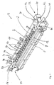
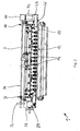
- the apparatus shown in the figures for applying fluid (hereinafter also referred to as application head) to a relative to the device movable substrate is used for applying liquid adhesive on the device before attached films.
- application head a relative to the device movable substrate
- other substrates such as packaging material or the like. Be coated with adhesive surface.
- the application head 1 has a metallic main body 2 and a fluid supply channel, which can be connected to an adhesive source, not shown, which is formed as a cylindrical bore in the base body 2 and to which a flexible adhesive line is connected.
- the main body has an upper part 3 and a lower part 5, which are screwed together.
- a cylindrical distribution channel 6 is arranged within the main body 2, which extends over the entire length of the applicator head 1.
- the distribution channel 6 is half formed as a semi-cylindrical recess in the upper part 3 and the other half in the lower part 5 as a semi-cylindrical recess, so that the distribution channel 6 can be easily cleaned.
- the distributor channel 6 communicates with a horizontally arranged slot 8 of a slot nozzle arrangement 10.
- the slot 8 opens into an elongate outlet opening 12 from which adhesive emerges during operation and is subsequently transferred to the substrate.
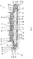
- Each order valve 14 is formed in the embodiment as a pneumatically actuated valve and each has a needle 16 (see Fig .. 3 and 4), which is coupled to a movably mounted in a cylinder pressure gas piston and movable upon application of the piston with pressure differences up and down is.
- the lower portion of the needle 16 cooperates with a formed on the base body 2 valve seat.
- a vertical connection bore is formed between the fluid supply channel 4 and the distribution channel 6, which is closed in the closed position of the application valve from the tip of the needle 16 and opened in the open position of the needle 16.
- the order valves 14 are connected to a compressed gas lines 17.
- a closure body 18 is movably disposed in the slot 8 of the slot nozzle assembly 10 and seals the slot 8 laterally.
- the closure body 18 is rigidly coupled to a cylindrical piston 20 which is arranged axially movable within the distribution channel 6.
- the closure body 18 extends from the piston 20 to the outlet opening 12 of the slot nozzle assembly 10.
- Such a closure body 18 with piston 20 is also disclosed in WO 00/67914, which is based on the present applicant and their descriptions, in particular with respect to the piston 20 with Closure body 18 is incorporated by reference into this disclosure.
- the applicator head 1 has two independently operable adjusting devices 22, 24, by means of which the pistons 20 can be moved together with the closure bodies 18 within the distributor channel 6 or the slot 8.
- the piston 20 and closing body 18, which can be seen on the right in FIG. 3, are part of the adjusting device 22.
- the left-hand piston 20 and closing body 18 in FIG. 3 are part of the adjusting device 24.
- Each adjusting device 22, 24 has a flexible element 26, 28 according to the invention, which is in each case coupled to the closure body 18 in a manner explained in more detail below and can be driven manually or by motor means of a toothed wheel 30, 32 which engages with the flexible element 26, 28 stands.
- the adjusting device 22 has a rotatable shaft 34 by means of a hand wheel 34, which is rotatably supported by means of two plates 36, 38 and not shown bearing on the base body 2.
- a reduction gear 40 in the form of a worm gear is used to reduce the rotational movement of the shaft 34.
- An input shaft of the transmission 42 is coupled to the shaft 34.
- An output shaft of the transmission 40 is coupled to a shaft 44 (see FIG. 3) which extends within a spacer tube 46 and drives the gearwheel 30 by a positive connection upon rotation of the handwheel 33.
- the flexible element 26 in the form of a push / pull chain is in positive engagement with the toothed wheel 30, so that it is moved when the shaft 44 rotates, with the piston 20 and the closure body 18 inside the distributor channel 6 or the slot 8 moves depending on the direction of rotation to vary the length of the slot 8.
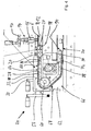
- the flexible element 26, the structure of which is explained in greater detail with reference to FIGS. 4 to 7, is arranged within a housing 46 and is guided in a guide channel 48.
- the guide channel 48 has a first, straight portion 50, which is substantially aligned with respect to the distribution channel 6 and the slot 8, a deflection portion 52 for deflecting the flexible member and a lower straight storage portion 54 for receiving the flexible member.
- the storage portion 54 is straight and arranged substantially parallel to the distribution channel 6 below the slot nozzle assembly.
- the housing 46 is mounted on the applicator head 1 and is preferably made of aluminum.
- the gear 30 is housed within a right in Figure 1 housing portion 47.
- the adjusting device 24 for the - left in the figures - closure body 18 is formed in principle as the adjusting device 22 and has a hand wheel 56 which is coupled to an input shaft of a reduction gear 58, whose output shaft with a shaft 60 for driving the gear 32 is connected.
- the flexible element 28 according to the invention is within a left Section 62 of the housing 46 disposed within a guide channel 64 and coupled at one end to the piston 20 and closure body 18.
- the guide channel 64 likewise has a first straight section 66, a subsequent deflecting section 88 and a lower storage section 70 which is connected to the flexible element storage section 54 shown in FIG.
- the flexible element 20, 26 has a stop element 72 at its end section arranged in the storage section 70 of the guide channel 64 or 48, which limits the movement of the flexible element by abutment against a stop surface 74 (see FIG. 4)
- the stop member 72 is essentially a cylindrical piston with an upper recess 76 and is connected by a pin 78 to the flexible member 20.
- the thrust members 88 have approximately U-shape in cross sections and, as can be seen in Figure 4, allow a curvature of the flexible elements.
- hand wheels 33, 56 and motor drives can be used, for example in the form of an electric motor to move the flexible elements 26, 28.
- a movable closure body 20 and a flexible member 28 together with adjustment may be provided, if appropriate for the application.
- the piston 20 is connected to the flexible element 26, 28 by means of pins 90 which are coupled to the last chain link 82.
- the flexible element 26, 28 is dimensioned such that it can be moved into the distribution channel 6 and is preferably guided in this defined manner, so that buckling during insertion is not possible.
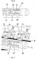
- FIG. 7 shows the flexible element 28 of the left-hand adjusting device 24 in the region of the storage section 70 of the guide channel 64 formed on the housing 46 together with two sensors in the form of mechanical switches 92, 94 shown enlarged.
- the switches 92, 94 each have a roller 98 fixed to a pivoting lever 96 which come into contact with the flexible element 28 and, in the case of contact, actuate a pin 100 so as to make contact and come in contact with the sensor (switches 92, 94) Signal is provided.
- This signal may be an electrical signal or a signal in the form of a gas pressure, which is transmitted through a gas line.
- the signal from the sensors is used to determine the position of the flexible element 28 and thus the position of the closure body and the piston 20 within the slot 8 and the distribution channel 6, respectively, so that, depending on the respective position, those application valves 14 (FIGS. 4) are activated, which lie in the region of the section between the two closure bodies 18 of the slot 8, while the other unused order valves 14 are then passivated, so that no fluid escapes there.
- Several sensors in the form of switches 94 are provided (see also FIG. 3) in order to be able to achieve activation or passivation corresponding to the number of application valves 14.
Landscapes
- Coating Apparatus (AREA)
- Nozzles (AREA)
- Polarising Elements (AREA)
Claims (16)
- Dispositif d'application de fluide sur un substrat pouvant être déplacé par rapport au dispositif, en particulier pour l'application d'une colle sur des feuilles, pourvu d'un canal d'alimentation de fluide (4) formé dans un corps de base (2) pouvant être relié à une source de fluide,
pourvu d'au moins une soupape d'application (14) pour interrompre ou pour libérer facultativement le flux de fluide, et
pourvu d'un agencement de buses à fente (10) communiquant avec le canal d'alimentation en fluide (4), lequel présente une fente longitudinale (8) pourvue d'une ouverture de sortie (12), la longueur de la fente (8) pouvant être modifiée à l'aide d'un corps de fermeture (18) pouvant être déplacé dans la fente (8) et bouchant celle-ci latéralement,
caractérisé en ce que le corps de fermeture (18) peut être déplacé à l'aide d'un élément flexible (26, 28), et est couplé à celui-ci. - Dispositif selon la revendication 1,
caractérisé en ce que l'élément flexible est une chaîne (80), une courroie dentée ou un câble. - Dispositif selon la revendication 2,
caractérisé en ce que l'élément flexible (26, 28) est une chaîne de poussée/traction. - Dispositif selon la revendication 3,
caractérisé en ce que la chaîne de poussée/traction présente une multitude de chaînons de poussée (88) adjacents à la chaîne (80) dans sa direction longitudinale et fixés à des maillons de chaîne respectifs (82, 84). - Dispositif selon l'une quelconque des revendications précédentes,
caractérisé en ce que l'élément flexible (26, 28) est relié au corps de fermeture (18) par une extrémité, et est en prise avec une roue dentée (30, 32) pouvant être actionnée dans le but de déplacer le corps de fermeture (18) manuellement ou de manière motorisée. - Dispositif selon l'une quelconque des revendications précédentes,
caractérisé en ce que l'élément flexible (26, 28) est guidé dans un canal de guidage (48, 64). - Dispositif selon la revendication 6,
caractérisé en ce que le canal de guidage (48, 64) comprend une première section (50, 51) essentiellement latéralement adjacente à la fente. - Dispositif selon la revendication 6 et/ou 7,
caractérisé en ce que le canal de guidage comprend un tronçon permettant le pivotement (52, 68) ainsi qu'un tronçon de stockage (54, 70) disposé à proximité de l'agencement de buses à fente (12), en vue du logement de l'élément flexible (26, 28). - Dispositif selon la revendication 8,
caractérisé en ce que le tronçon de stockage (54, 70) est essentiellement droit, et est disposé de manière parallèle et en dessous par rapport à l'agencement de buses à fente (10). - Dispositif selon au moins l'une quelconque des revendications précédentes,
caractérisé en ce que le canal de guidage (48, 64) peut être formé essentiellement à l'intérieur d'un carter séparé (46), lequel peut être monté sur l'agencement de buses à fente (10). - Dispositif selon l'une quelconque des revendications précédentes,
caractérisé en ce qu'un élément de butée (72) est formé sur un tronçon, de préférence une extrémité de l'élément flexible, dans le but de limiter la capacité de déplacement de l'élément flexible. - Dispositif selon au moins l'une quelconque des revendications précédentes,
caractérisé en ce que la position de l'élément flexible peut être détectée à l'aide d'au moins un capteur, de préférence un commutateur mécanique (92, 94) et en ce que une ou plusieurs soupapes d'application (14) peuvent être ouverte(s) ou fermée(s) à l'aide du signal mis à disposition par le capteur, dans le but d'interrompre ou de libérer le flux de fluide. - Dispositif selon au moins l'une quelconque des revendications précédentes,
caractérisé en ce que deux corps de fermeture bouchant latéralement la fente et deux éléments flexibles pouvant être actionnés indépendamment l'un de l'autre, sont prévus dans le but de déplacer le corps de fermeture. - Dispositif selon la revendication 13,
caractérisé en ce qu'au moins un des deux éléments flexibles peut être actionné à l'aide d'un arbre logé de manière à pouvoir tourner et s'étendant essentiellement sur toute la longueur de l'agencement de buses à fente. - Dispositif selon la revendication 13 et/ou 14,
caractérisé en ce que les deux éléments flexibles, chacun d'entre eux étant couplé à un arbre avec un volant (33) pour le réglage manuel, peuvent être déplacés. - Dispositif selon la revendication 15,
caractérisé en ce qu'un engrenage, de préférence un engrenage à vis sans fin, est monté entre l'arbre et la roue dentée.
Applications Claiming Priority (3)
| Application Number | Priority Date | Filing Date | Title |
|---|---|---|---|
| DE20308337U DE20308337U1 (de) | 2003-05-26 | 2003-05-26 | Vorrichtung zum Auftragen von Fluid |
| DE20308337U | 2003-05-26 | ||
| PCT/EP2004/005594 WO2004103577A1 (fr) | 2003-05-26 | 2004-05-25 | Dispositif d'application de fluide |
Publications (2)
| Publication Number | Publication Date |
|---|---|
| EP1501640A1 EP1501640A1 (fr) | 2005-02-02 |
| EP1501640B1 true EP1501640B1 (fr) | 2006-11-22 |
Family
ID=27763218
Family Applications (1)
| Application Number | Title | Priority Date | Filing Date |
|---|---|---|---|
| EP04734665A Expired - Lifetime EP1501640B1 (fr) | 2003-05-26 | 2004-05-25 | Dispositif d'application de fluide |
Country Status (5)
| Country | Link |
|---|---|
| EP (1) | EP1501640B1 (fr) |
| AT (1) | ATE345879T1 (fr) |
| DE (2) | DE20308337U1 (fr) |
| ES (1) | ES2275221T3 (fr) |
| WO (1) | WO2004103577A1 (fr) |
Families Citing this family (5)
| Publication number | Priority date | Publication date | Assignee | Title |
|---|---|---|---|---|
| EP1902787B1 (fr) | 2006-09-22 | 2013-06-05 | Nordson Corporation | Appareil d'application de produit fluide, en particulier d'adhésif thermofusible |
| DE202006014743U1 (de) | 2006-09-22 | 2006-11-23 | Nordson Corporation, Westlake | Vorrichtung zum Auftragen von Fluiden wie Klebstoff, insbesondere Schmelzkleber |
| DE202007002156U1 (de) | 2007-02-09 | 2007-04-12 | Nordson Corp | Vorrichtung zum Auftragen von Fluiden wie Klebstoff |
| US8640641B2 (en) | 2010-07-02 | 2014-02-04 | Nordson Corporation | Multi-slot applicator with automatic closing function |
| DE102024125473A1 (de) * | 2024-09-05 | 2026-03-05 | Viscotec Pumpen-U. Dosiertechnik Gmbh | Breitenvariable Auftragsdüse und Auftragssystem |
Family Cites Families (6)
| Publication number | Priority date | Publication date | Assignee | Title |
|---|---|---|---|---|
| US4248579A (en) * | 1979-10-10 | 1981-02-03 | Jyohoku Seiko Co., Ltd. | Film extrusion die |
| DE4130432C2 (de) | 1991-09-13 | 1995-04-06 | Kuesters Eduard Maschf | Auftragselement für flüssiges, schaumförmiges oder pastenförmiges Auftragsmedium |
| US6423144B1 (en) | 1996-08-07 | 2002-07-23 | Matsushita Electric Industrial Co., Ltd. | Coating apparatus and coating method |
| DE19830728C2 (de) | 1998-07-09 | 2001-08-02 | Reinhard Duespohl Maschb Gmbh | Kleber-Auftragsvorrichtung |
| DE29908150U1 (de) | 1999-05-10 | 1999-08-05 | Nordson Corporation, Westlake, Ohio | Vorrichtung zum Auftragen von Fluid |
| DE10129627C1 (de) * | 2001-06-20 | 2003-02-06 | Reifenhaeuser Masch | Extrusionsdüse |
-
2003
- 2003-05-26 DE DE20308337U patent/DE20308337U1/de not_active Expired - Lifetime
-
2004
- 2004-05-25 ES ES04734665T patent/ES2275221T3/es not_active Expired - Lifetime
- 2004-05-25 WO PCT/EP2004/005594 patent/WO2004103577A1/fr not_active Ceased
- 2004-05-25 EP EP04734665A patent/EP1501640B1/fr not_active Expired - Lifetime
- 2004-05-25 DE DE502004002056T patent/DE502004002056D1/de not_active Expired - Lifetime
- 2004-05-25 AT AT04734665T patent/ATE345879T1/de not_active IP Right Cessation
Also Published As
| Publication number | Publication date |
|---|---|
| WO2004103577A1 (fr) | 2004-12-02 |
| DE502004002056D1 (de) | 2007-01-04 |
| DE20308337U1 (de) | 2003-08-14 |
| ES2275221T3 (es) | 2007-06-01 |
| EP1501640A1 (fr) | 2005-02-02 |
| ATE345879T1 (de) | 2006-12-15 |
Similar Documents
| Publication | Publication Date | Title |
|---|---|---|
| EP1181105B1 (fr) | Dispositif pour l'application de fluide | |
| DE69230831T3 (de) | Setzgeräte und klebeband dafür | |
| EP1027167B1 (fr) | Applicateur d'adhesif thermofusible | |
| DE4004726C2 (de) | Antriebseinheit eines Rollapparates einer Papiermaschine | |
| DE3532514C1 (de) | Antriebsvorrichtung fuer eine Drehsaeule,insbesondere zur Bewegung von Schwenktuerfluegeln an Kraftfahrzeugen | |
| EP0850697A2 (fr) | Dispositif pour l'application de matériaux fluides sur un substrat, en particulier pour l'application intermittente de colles fluides | |
| EP0958122B1 (fr) | Chenille individuelle destinee a des dispositifs d'evacuation, et dispositifs d'evacuation pour elements allonges | |
| DE3426251A1 (de) | Umreifungsvorrichtung | |
| EP2377623B1 (fr) | Dispositif d'application d'une matière liquide sur un substrat | |
| EP1501640B1 (fr) | Dispositif d'application de fluide | |
| WO2008028970A1 (fr) | Dispositif pour la distribution de matière visqueuse ou pâteuse | |
| DE4334681C2 (de) | Bewegungseinheit zur Erzeugung einer Linearbewegung | |
| DE2100171B2 (de) | Vorrichtung zur Verhinderung des Durchhängens und zur Aufrechterhaltung einer Spannung in Kabeln, Drahtseilen u.dgl | |
| EP0466006B1 (fr) | Support de râcle pour un dispositif d'enduction | |
| DE29907968U1 (de) | Vorrichtung zum Abgeben von Fluid, insbesondere Klebstoff | |
| EP0089384B1 (fr) | Installation pour l'approvisionnement de brûleurs déplaçables avec liquide de pression | |
| DE69500823T2 (de) | Tragleiterführungsmechanismus für Jalousiezusammensetzungsapparat | |
| EP3336019B1 (fr) | Appareil d'ajustage | |
| EP4157729B1 (fr) | Machine de cerclage ajustable | |
| DE202006019724U1 (de) | Vorrichtung mit Schlitzdüsenanordnung zum Abgeben von Fluid | |
| DE19532920A1 (de) | Auftragswerk zum direkten oder indirekten Auftragen eines flüssigen oder pastösen Mediums auf eine laufende Materialbahn | |
| DE4324052A1 (de) | Vorrichtung zum steuerbaren Befetten von Werkstücken mit über einen Riementrieb und eine Antriebswelle von einem Motor gedrehten Befettungswalzen | |
| DE202009014160U1 (de) | Schlitzdüsenvorrichtung | |
| DE112010005731B4 (de) | Schwenkvorrichtung zum Schwenkbewegen von Massen, insbesondere zur Verwendung im Karosseriebau der Kfz-Industrie | |
| DE19647775A1 (de) | Versiegelungsvorrichtung für aseptisch befüllte Packungen unter keimfreien Bedingungen |
Legal Events
| Date | Code | Title | Description |
|---|---|---|---|
| PUAI | Public reference made under article 153(3) epc to a published international application that has entered the european phase |
Free format text: ORIGINAL CODE: 0009012 |
|
| 17P | Request for examination filed |
Effective date: 20041112 |
|
| AK | Designated contracting states |
Kind code of ref document: A1 Designated state(s): AT BE BG CH CY CZ DE DK EE ES FI FR GB GR HU IE IT LI LU MC NL PL PT RO SE SI SK TR |
|
| AX | Request for extension of the european patent |
Extension state: AL HR LT LV MK |
|
| GRAP | Despatch of communication of intention to grant a patent |
Free format text: ORIGINAL CODE: EPIDOSNIGR1 |
|
| DAX | Request for extension of the european patent (deleted) | ||
| GRAS | Grant fee paid |
Free format text: ORIGINAL CODE: EPIDOSNIGR3 |
|
| GRAA | (expected) grant |
Free format text: ORIGINAL CODE: 0009210 |
|
| AK | Designated contracting states |
Kind code of ref document: B1 Designated state(s): AT BE BG CH CY CZ DE DK EE ES FI FR GB GR HU IE IT LI LU MC NL PL PT RO SE SI SK TR |
|
| PG25 | Lapsed in a contracting state [announced via postgrant information from national office to epo] |
Ref country code: IE Free format text: LAPSE BECAUSE OF FAILURE TO SUBMIT A TRANSLATION OF THE DESCRIPTION OR TO PAY THE FEE WITHIN THE PRESCRIBED TIME-LIMIT Effective date: 20061122 Ref country code: PL Free format text: LAPSE BECAUSE OF FAILURE TO SUBMIT A TRANSLATION OF THE DESCRIPTION OR TO PAY THE FEE WITHIN THE PRESCRIBED TIME-LIMIT Effective date: 20061122 Ref country code: FI Free format text: LAPSE BECAUSE OF FAILURE TO SUBMIT A TRANSLATION OF THE DESCRIPTION OR TO PAY THE FEE WITHIN THE PRESCRIBED TIME-LIMIT Effective date: 20061122 Ref country code: NL Free format text: LAPSE BECAUSE OF FAILURE TO SUBMIT A TRANSLATION OF THE DESCRIPTION OR TO PAY THE FEE WITHIN THE PRESCRIBED TIME-LIMIT Effective date: 20061122 Ref country code: SK Free format text: LAPSE BECAUSE OF FAILURE TO SUBMIT A TRANSLATION OF THE DESCRIPTION OR TO PAY THE FEE WITHIN THE PRESCRIBED TIME-LIMIT Effective date: 20061122 Ref country code: RO Free format text: LAPSE BECAUSE OF FAILURE TO SUBMIT A TRANSLATION OF THE DESCRIPTION OR TO PAY THE FEE WITHIN THE PRESCRIBED TIME-LIMIT Effective date: 20061122 Ref country code: CZ Free format text: LAPSE BECAUSE OF FAILURE TO SUBMIT A TRANSLATION OF THE DESCRIPTION OR TO PAY THE FEE WITHIN THE PRESCRIBED TIME-LIMIT Effective date: 20061122 Ref country code: SI Free format text: LAPSE BECAUSE OF FAILURE TO SUBMIT A TRANSLATION OF THE DESCRIPTION OR TO PAY THE FEE WITHIN THE PRESCRIBED TIME-LIMIT Effective date: 20061122 |
|
| REG | Reference to a national code |
Ref country code: GB Ref legal event code: FG4D Free format text: NOT ENGLISH |
|
| GBT | Gb: translation of ep patent filed (gb section 77(6)(a)/1977) |
Effective date: 20061122 |
|
| REG | Reference to a national code |
Ref country code: CH Ref legal event code: EP |
|
| REG | Reference to a national code |
Ref country code: IE Ref legal event code: FG4D Free format text: LANGUAGE OF EP DOCUMENT: GERMAN |
|
| REF | Corresponds to: |
Ref document number: 502004002056 Country of ref document: DE Date of ref document: 20070104 Kind code of ref document: P |
|
| PG25 | Lapsed in a contracting state [announced via postgrant information from national office to epo] |
Ref country code: BG Free format text: LAPSE BECAUSE OF FAILURE TO SUBMIT A TRANSLATION OF THE DESCRIPTION OR TO PAY THE FEE WITHIN THE PRESCRIBED TIME-LIMIT Effective date: 20070222 Ref country code: DK Free format text: LAPSE BECAUSE OF FAILURE TO SUBMIT A TRANSLATION OF THE DESCRIPTION OR TO PAY THE FEE WITHIN THE PRESCRIBED TIME-LIMIT Effective date: 20070222 Ref country code: SE Free format text: LAPSE BECAUSE OF FAILURE TO SUBMIT A TRANSLATION OF THE DESCRIPTION OR TO PAY THE FEE WITHIN THE PRESCRIBED TIME-LIMIT Effective date: 20070222 |
|
| PG25 | Lapsed in a contracting state [announced via postgrant information from national office to epo] |
Ref country code: PT Free format text: LAPSE BECAUSE OF FAILURE TO SUBMIT A TRANSLATION OF THE DESCRIPTION OR TO PAY THE FEE WITHIN THE PRESCRIBED TIME-LIMIT Effective date: 20070423 |
|
| NLV1 | Nl: lapsed or annulled due to failure to fulfill the requirements of art. 29p and 29m of the patents act | ||
| REG | Reference to a national code |
Ref country code: ES Ref legal event code: FG2A Ref document number: 2275221 Country of ref document: ES Kind code of ref document: T3 |
|
| ET | Fr: translation filed | ||
| REG | Reference to a national code |
Ref country code: IE Ref legal event code: FD4D |
|
| PLBE | No opposition filed within time limit |
Free format text: ORIGINAL CODE: 0009261 |
|
| STAA | Information on the status of an ep patent application or granted ep patent |
Free format text: STATUS: NO OPPOSITION FILED WITHIN TIME LIMIT |
|
| 26N | No opposition filed |
Effective date: 20070823 |
|
| BERE | Be: lapsed |
Owner name: NORDSON CORP. Effective date: 20070531 |
|
| PG25 | Lapsed in a contracting state [announced via postgrant information from national office to epo] |
Ref country code: MC Free format text: LAPSE BECAUSE OF NON-PAYMENT OF DUE FEES Effective date: 20070531 |
|
| PG25 | Lapsed in a contracting state [announced via postgrant information from national office to epo] |
Ref country code: BE Free format text: LAPSE BECAUSE OF NON-PAYMENT OF DUE FEES Effective date: 20070531 |
|
| PG25 | Lapsed in a contracting state [announced via postgrant information from national office to epo] |
Ref country code: GR Free format text: LAPSE BECAUSE OF FAILURE TO SUBMIT A TRANSLATION OF THE DESCRIPTION OR TO PAY THE FEE WITHIN THE PRESCRIBED TIME-LIMIT Effective date: 20070223 |
|
| PG25 | Lapsed in a contracting state [announced via postgrant information from national office to epo] |
Ref country code: AT Free format text: LAPSE BECAUSE OF NON-PAYMENT OF DUE FEES Effective date: 20070525 |
|
| REG | Reference to a national code |
Ref country code: CH Ref legal event code: PL |
|
| PG25 | Lapsed in a contracting state [announced via postgrant information from national office to epo] |
Ref country code: CH Free format text: LAPSE BECAUSE OF NON-PAYMENT OF DUE FEES Effective date: 20080531 Ref country code: LI Free format text: LAPSE BECAUSE OF NON-PAYMENT OF DUE FEES Effective date: 20080531 Ref country code: EE Free format text: LAPSE BECAUSE OF FAILURE TO SUBMIT A TRANSLATION OF THE DESCRIPTION OR TO PAY THE FEE WITHIN THE PRESCRIBED TIME-LIMIT Effective date: 20061122 |
|
| PG25 | Lapsed in a contracting state [announced via postgrant information from national office to epo] |
Ref country code: CY Free format text: LAPSE BECAUSE OF FAILURE TO SUBMIT A TRANSLATION OF THE DESCRIPTION OR TO PAY THE FEE WITHIN THE PRESCRIBED TIME-LIMIT Effective date: 20061122 Ref country code: LU Free format text: LAPSE BECAUSE OF NON-PAYMENT OF DUE FEES Effective date: 20070525 |
|
| PG25 | Lapsed in a contracting state [announced via postgrant information from national office to epo] |
Ref country code: TR Free format text: LAPSE BECAUSE OF FAILURE TO SUBMIT A TRANSLATION OF THE DESCRIPTION OR TO PAY THE FEE WITHIN THE PRESCRIBED TIME-LIMIT Effective date: 20061122 Ref country code: HU Free format text: LAPSE BECAUSE OF FAILURE TO SUBMIT A TRANSLATION OF THE DESCRIPTION OR TO PAY THE FEE WITHIN THE PRESCRIBED TIME-LIMIT Effective date: 20070523 |
|
| PGFP | Annual fee paid to national office [announced via postgrant information from national office to epo] |
Ref country code: FR Payment date: 20110607 Year of fee payment: 8 |
|
| PGFP | Annual fee paid to national office [announced via postgrant information from national office to epo] |
Ref country code: GB Payment date: 20110520 Year of fee payment: 8 |
|
| PGFP | Annual fee paid to national office [announced via postgrant information from national office to epo] |
Ref country code: DE Payment date: 20120523 Year of fee payment: 9 |
|
| PGFP | Annual fee paid to national office [announced via postgrant information from national office to epo] |
Ref country code: IT Payment date: 20120525 Year of fee payment: 9 |
|
| PGFP | Annual fee paid to national office [announced via postgrant information from national office to epo] |
Ref country code: ES Payment date: 20120525 Year of fee payment: 9 |
|
| GBPC | Gb: european patent ceased through non-payment of renewal fee |
Effective date: 20120525 |
|
| REG | Reference to a national code |
Ref country code: FR Ref legal event code: ST Effective date: 20130131 |
|
| PG25 | Lapsed in a contracting state [announced via postgrant information from national office to epo] |
Ref country code: GB Free format text: LAPSE BECAUSE OF NON-PAYMENT OF DUE FEES Effective date: 20120525 Ref country code: FR Free format text: LAPSE BECAUSE OF NON-PAYMENT OF DUE FEES Effective date: 20120531 |
|
| PG25 | Lapsed in a contracting state [announced via postgrant information from national office to epo] |
Ref country code: DE Free format text: LAPSE BECAUSE OF NON-PAYMENT OF DUE FEES Effective date: 20131203 |
|
| REG | Reference to a national code |
Ref country code: DE Ref legal event code: R119 Ref document number: 502004002056 Country of ref document: DE Effective date: 20131203 |
|
| PG25 | Lapsed in a contracting state [announced via postgrant information from national office to epo] |
Ref country code: IT Free format text: LAPSE BECAUSE OF NON-PAYMENT OF DUE FEES Effective date: 20130525 |
|
| REG | Reference to a national code |
Ref country code: ES Ref legal event code: FD2A Effective date: 20140609 |
|
| PG25 | Lapsed in a contracting state [announced via postgrant information from national office to epo] |
Ref country code: ES Free format text: LAPSE BECAUSE OF NON-PAYMENT OF DUE FEES Effective date: 20130526 |