EP1501998B1 - Fenêtre à résistance améliorée aux explosions - Google Patents
Fenêtre à résistance améliorée aux explosions Download PDFInfo
- Publication number
- EP1501998B1 EP1501998B1 EP03728476A EP03728476A EP1501998B1 EP 1501998 B1 EP1501998 B1 EP 1501998B1 EP 03728476 A EP03728476 A EP 03728476A EP 03728476 A EP03728476 A EP 03728476A EP 1501998 B1 EP1501998 B1 EP 1501998B1
- Authority
- EP
- European Patent Office
- Prior art keywords
- blast
- window
- bracket
- assembly
- explosion
- Prior art date
- Legal status (The legal status is an assumption and is not a legal conclusion. Google has not performed a legal analysis and makes no representation as to the accuracy of the status listed.)
- Expired - Lifetime
Links
Images



Classifications
-
- E—FIXED CONSTRUCTIONS
- E06—DOORS, WINDOWS, SHUTTERS, OR ROLLER BLINDS IN GENERAL; LADDERS
- E06B—FIXED OR MOVABLE CLOSURES FOR OPENINGS IN BUILDINGS, VEHICLES, FENCES OR LIKE ENCLOSURES IN GENERAL, e.g. DOORS, WINDOWS, BLINDS, GATES
- E06B5/00—Doors, windows, or like closures for special purposes; Border constructions therefor
- E06B5/10—Doors, windows, or like closures for special purposes; Border constructions therefor for protection against air-raid or other war-like action; for other protective purposes
- E06B5/12—Doors, windows, or like closures for special purposes; Border constructions therefor for protection against air-raid or other war-like action; for other protective purposes against air pressure, explosion, or gas
-
- Y—GENERAL TAGGING OF NEW TECHNOLOGICAL DEVELOPMENTS; GENERAL TAGGING OF CROSS-SECTIONAL TECHNOLOGIES SPANNING OVER SEVERAL SECTIONS OF THE IPC; TECHNICAL SUBJECTS COVERED BY FORMER USPC CROSS-REFERENCE ART COLLECTIONS [XRACs] AND DIGESTS
- Y10—TECHNICAL SUBJECTS COVERED BY FORMER USPC
- Y10S—TECHNICAL SUBJECTS COVERED BY FORMER USPC CROSS-REFERENCE ART COLLECTIONS [XRACs] AND DIGESTS
- Y10S52/00—Static structures, e.g. buildings
- Y10S52/04—Magnetic connecting means for building components
Definitions
- the present invention relates to windows, and more particularly to windows that resist explosive forces.
- a blast-resistant window assembly comprising a window, and first and second brackets.
- the window is fitted within an opening having at least one wall.
- the first bracket comprises a brace located adjacent the window, and a stop located adjacent the opposing wall.
- the second bracket is located adjacent the wall, and is configured to receive the stop. During an explosion, force created therefrom causes the window to engage the brace of the first bracket to cause the stop of same to be received by the second bracket.
- the window assembly may comprise: a window arcuately deforming to distribute the force on the same; the window engaging a brace creating a space between the wall and the window to allow pressure created by the force of the explosion to pass therebetween; a slot existing between a first bracket and the window prior to an explosion; a window comprising a sash located at the periphery thereof; a portion of the sash engaging the brace portion of the first bracket; a prime window fitted within an opening and facing the window opposite the first and second brackets; a blind located within the opening and positioned between the prime window and the window; the window being a storm window; and the window being laminated with a film.
- a blast-resistant window assembly also comprising a window with first and second brackets.
- the window has a face and an end. The end of the window is fitted within an opening having at least one side wall.
- the first bracket comprises a length, a brace located adjacent the face of the window, a stop which extends from the brace and located generally perpendicular to and adjacent the side wall, and a protrusion extending from the brace and located adjacent the end of the window.
- the brace, stop, and protrusion extend at least a portion of the length of the first bracket.
- the second bracket also has a length, and has a channel with an opening that faces the stop of the first bracket to receive the stop during an explosion.
- the window assembly may comprise: a window engaging the brace of a first bracket to cause a stop of the same to engage the channel of a second bracket; a slot being located between the brace of the first bracket and the window; the brace of the first bracket abutting the window; a third bracket being removably attached to the window, wherein the window separates from the third bracket during an explosion; the length of the first bracket extending along an arcuate path; the length of the second bracket also extending along an arcuate path; the window deforming along the arcuate path of the first bracket during an explosion; the brace of the first bracket having a slot disposed therein which receives and moves the first bracket relative to a stationary member during an explosion.
- a blast-resistant window assembly comprising a window, a T-bracket, and a J-bracket.
- the window is fitted within an opening.
- the T-bracket is located adjacent the window, and has a means for maintaining the window during an explosion.
- the J-bracket is located adjacent the T-bracket, and is configured to receive the same for maintaining the window during the explosion.
- FIG. 1 A top cross-sectional view of an embodiment of a blast-resistant window assembly 2 is shown in Fig. 1 .
- the assembly 2 is located within a wall opening 4 between an interior 6 and an exterior 8 of a building or dwelling.
- the assembly 2 is attached to walls or outer frame 10. It is appreciated, however, that, to one skilled in the art of windows or window openings of conventional type, this disclosed assembly can be adapted and used with any frame or window opening of any size or configuration.
- the application herein uses the term "window,” it is appreciated that “window” is contemplated to possibly include doors, wall units, etc., depending on the application.
- assembly 2 is configured to withstand impact forces created exterior 8 of the building with the blast of the explosion being directed into the interior 6.
- the embodiment of assembly 2, shown in Fig. 1 comprises an outer window 12, like that of a prime window, for example, which spans between portions of outer frame 10 as shown.
- Blinds 14 can also be included which are located adjacent to outer window 12 toward the interior 6.
- a bracket 16 is illustratively located on each of the opposing walls or outer frame 10 and is adjacent blind 14.
- a blast window 18 is removably attached to bracket 16 via sash 20 which is engagable with magnets 22 or other comparable adhesives, fasteners, or coupling members.
- T-brackets 24 each attach to one of the opposing walls or outer frame 10, and each comprise a protrusion portion 26, a brace 28, and a stop 30.
- J-brackets 32 each also attach to opposing outer frames 10, and each having a backing 34 which attaches to outer frame 10, and also having a catch 36 configured to abut stop 30 of T-bracket 24.
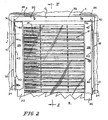
- Fig. 1 The embodiment shown in Fig. 1 is also shown in a face-elevational view in Fig. 2 from the interior 6 perspective. This view shows the relative locations of the T-brackets 24 and J-brackets 32 to blast window 18. Also shown is top rail channel 38 located on the top portion of outer frame 10. In this embodiment and as shown further herein, sash 20 is fitted within top rail channel 38 to assist in keeping blast window 18 in place during an explosion. Also shown in Fig. 2 are fasteners 40 which are disposed through stop 30 and enter frame 10 to keep T-bracket 24 in place. It is appreciated that the fasteners 40 can be bolts, screws, adhesives, or other comparable fastening means that one skilled in the art would recognize useful to keep the T-bracket 24 in place. Further, shown in Fig. 2 is the brace 28 of T-bracket 24 covering a portion of sash 20.
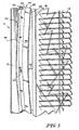
- FIG. 3 A perspective view of the illustrative assembly 2 is shown in Fig. 3 .
- This view shows the illustrative relationship between sash 20, and T-bracket 24 and J-bracket 32 prior to receiving an impact force from an explosion. Both the T-bracket 24 and the J-bracket 32 extend along an arcuate path relative to sash 20. This provides a gap or slot 42 located between sash 20 and the brace 28 portion of T-bracket 24.
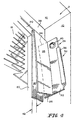
- FIG. 4 A detailed perspective view of assembly 2 is shown in Fig. 4 which, again, shows the slot 42 located between sash 20 and brace 28 of T-bracket 24.
- T-bracket 24 is shown not to extend beyond top rail channel 38. This assists in greater ease and removal of blast window 18 from assembly 2, if desired. It is contemplated, however, that other embodiments include a brace or other structure that extends beyond top rail 38.
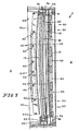
- FIG. 5 A cross-sectional view of the blast-resistant window assembly 2 being subject to a blast force caused by an explosion is shown in Fig. 5 .
- a blast force indicated by reference numeral 50, is directed from the exterior 8 to the interior 6, breaching the outer window 12, directing debris in the direction of interior 6.
- the blind 14 is attached to the assembly via attachments 46 and 48.
- the force of blast 50 may cause debris from window 12, to an extent, to be consolidated in blind 14, with attachments 46, 48, in many instances, keeping blinds 14 from detaching from the assembly.
- the force caused by the blast is sufficient to separate blast window 18 from bracket 16.
- the magnets 22 are attached to the sash 20 of blast window 18 on the face opposite bracket 16. Under normal use conditions, as shown in Fig. 1 , it is appreciated that such an attachment maintains an effective connection between blast window 18 and bracket 16.
- the force of blast 50 may cause separation between blast window 18 and bracket 16.
- the separation between sash 20 and bracket 16 allows the blast force 50 to pass between any space created by blast window 18 and opening 4 to allow that force into the interior 6 as shown in Fig. 5 . Allowing this force 50 to enter the interior 6 relieves the stress forces that would otherwise be applied to blast window 18.
- the separation can be of any type to facilitate release of pressure or energy through assembly 2.
- tab portions 39 of bracket 16 are seated within both top and bottom rail channels 38, 52, respectively, for construction purposes.
- the T-bracket 24 and J-bracket 32 assist in maintaining blast window 18 essentially in place during the blast.
- the bracket being an arcuate path causes window 18 to temporarily deform by conforming to the arcuate path. This allows the force exerted on blast window 18 to be more effectively dissipated throughout blast window 18, rather than isolated to a single portion or point on blast window 18. Because materials, such as metals, plastic, and glass, for example, are known to be, to some extent, flexible, such can be used to form an arcuate path as shown in Fig. 5 without the blast window 18 being destroyed.
- top rail channel 38 is complimented by a bottom rail channel 52 to hold blast window 18 in place. Whereas the top rail channel 38 holds the top portion of blast window 18, the bottom rail channel 52 similarly holds the bottom portion of blast window 18.
- a blind adjustment mechanism 53 is positioned below bottom rail channel 52. Adjustment mechanism 53 is in communication with blind 14 to allow an operator in the interior 6 to open, close, or otherwise adjust the positioning of blind 14.
- Mechanism 53 can be of any type known to those skilled in die art, as well as placed in any sufficient location to serve its function.
- FIG. 6 The top detail view of Fig. 6 , along with the side detail view of Fig. 7 , further illustrates assembly 2.
- FIG. 6 when a blast occurs from the exterior 8, creating blast force 50 which may break outer window 12, that same force also causes magnet 22, attached to sash 20, to separate itself and, therefore, allow blast window 18 and bracket 16 to separate.
- this separation allows the blast force 50 to penetrate and pass through into the interior 6, relieving the force that is actually exerted on blast window 18.
- blast window 18 is separated from bracket 16, it is held to assembly 2 by the brace 28 of T-bracket 24.
- the force 50 causes blast window 18 to abut against brace 28, which, being attached to stop 30, causes the same to engage and be caught in catch 36 of J-bracket 32.
- This interaction while allowing the blast window 18 to bend to distribute the force exerted on it by force 50, holds blast window 18 generally in place, preventing it from shattering and entering the interior 6 along with the debris.
- Protrusion 26 is positioned adjacent the edge of blast window 18 and generally perpendicularly to brace 28. Protrusion 26 illustratively creates a wedging-like effect with respect to blast window 18 to add further strength and holding power to T-bracket 24. As shown in Fig.
- brace 28 is moved generally in direction 56, causing a portion of protrusion 26 to wedge against blast window 18 by moving generally in direction 58. This action assists in distributing the force on stop 30, not only in direction 60, but also in direction 62. This allows the strength of the wall to absorb some of the force caused by the explosion.
- FIG. 7 illustrates how blast window 18 is allowed to bend according to the arcuate path formed by T-bracket 24 and J-bracket 32 without extricating itself from assembly 2.
- blast window 18 When blast window 18 is separated from bracket 16, blast window 18 remains in top rail channel 38, as well as bottom rail channel 52. (See, also, Fig. 5 .)
- a portion of force 50 exerted on blast window 18 can be absorbed by T-bracket and J-bracket 24,32, respectively, without the ends of blast window 18 being removed from top and bottom rail channels 38, 52, respectively.
- Blast window 18 may comprise dual panels of tempered glass panes with a film material lamented therebetween. This composite, commonly referred to as safety glass, is used so that if the glass breaks, it will shatter into small pieces, which do not have sharp edges. This will better protect any occupant in interior 6 from the glass.
- blast window 18 may be a tempered laminate, comprising two pieces of tempered/clear laminate, with a laminate film located therebetween corresponding to the degree of strength required.
- another embodiment may comprise a combination of tempered and annealed laminate, clear tempered to clear annealed, with a laminate film located therebetween.
- Another embodiment may be an annealed laminate, comprising two pieces of annealed laminate glass, with a substantial laminate thickness corresponding to the degree of strength required. And yet, another embodiment may comprise a tempered glass with an approximate 0.04 film coated thereon to keep broken fragments together.
- a composite of annealed (non-tempered) low emissivity or "low E” glass may also be laminated with a clear tempered pane. Because it is known by those skilled in the art that low E tempered glass and conventional tempered glass bow at different rates, such combinations are difficult to laminate. Typically, the low E tempered glass experiences a greater radius of curvature than the tempered glass. Accordingly, the annealed low E glass, having less bow than tempered low E glass, may, alternatively, be laminated with conventional tempered clear glass to provide both low E benefits and high strength. This can be particularly useful where the glass bows to form the arcuate path defined by the J-bracket 32. A film laminate can be used to provide further strength between these panes of glass.
- FIG. 8 Another embodiment of a blast-resistant window assembly 70 is shown in Figs. 8 through 12 .
- assembly 70 similar to assembly 2, includes a blast window 18 with blinds 14, and has T- and J-brackets 72, 74, respectively, which fasten to each opposing side of frame 10.
- the T-bracket 72 is positioned substantially perpendicular to sash 20 prior to the impact of a blast, as opposed to the assembly 2 having the arcuate T-bracket 24.
- the stop 75 of T-bracket 72 is positioned adjacent to, yet, not within the catch 94 of J-bracket 74.
- T-bracket 72 This allows T-bracket 72 to be placed and fastened against frame 10 without having to be fitted within catch 94, thereby easing installation. Also shown in Fig. 8 are fasteners 78 which attach J-bracket 74 to frame 10. T-bracket 72 is shown having a brace 80 that is positioned parallel to sash 20. The stop 75 of T-bracket 72 includes a slot 82 configured to receive a post or screw 84 as shown therein.
- FIG. 9 Another perspective view of assembly 70 is shown in Fig. 9 .
- This view shows, similar to the embodiment of assembly 2, sash 20 or blast window 18 extending into a top rail channel 38 and bottom rail channel 52, along with blinds 14 located between windows 12 and 18.
- a cover 86 is shown positioned adjacent frame wall 10. Cover 86 is configured to shroud T-bracket 72 and J-bracket 74.
- cover 86 includes depending portions 88 which provides for a cavity 90 located between cover 86 and frame 10. Within this cavity 90, T-bracket 72 and J-bracket 74 are located to keep the same out of view.
- a slot 92 is formed between brace 80 and extending member 95 within which one of the depending members 88 is seated.
- the cover 86 may extend generally the length of blast window 18.
- FIG. 10 A cross-sectional view of assembly 70 is shown in Fig. 10 while being subjected to the force of an explosion.
- This embodiment operates similar to the embodiment described specifically in Fig. 5 .
- the exterior directional blast force 50 again, may breach outer window 12, directing debris and blast force 50 toward interior 6.
- a blind 14 is attached to assembly 70 via attachments 46 and 48, similar to that of assembly 2.
- a distinction between assembly 70 and assembly 2 is that, as blast window 18 of assembly 70 is caused to bow as a result of the blast force 50, T-bracket 72, normally linearly oriented, bows correspondingly to the arcuate path of J-bracket 74.
- the slot and pin structures 82, 84 serve as a guide so that the movement of T-bracket 72 during an explosion is limited to engaging J-bracket 74. As stop 75 of T-bracket 72 moves to engage catch 94, J-bracket 74 and slot 82 move with respect to pin 84. It is contemplated that other structures can be used to guide T-bracket 72 as described.
- assembly 70 contemplates that the force 50 caused by the blast separates blast window 18 from bracket 16, allowing the pressure or blast force 50 to pass through the periphery of blast window 18 and into the interior 6 as shown in both Fig. 10 and Fig. 5 .
- assembly 70 includes T-bracket 72 and J-bracket 74 assisting to maintain blast window 18 essentially in place during the blast. Because T-bracket 72 and blast window 18 do move a minor extent to form the arcuate path, the force exerted on blast window 18 is allowed to be more effectively distributed and dissipated throughout blast window 18, rather than be concentrated at an isolated portion of the window.
- the top rail channel 38 and a bottom rail channel 52 allow the span of blast window 18 to bend in the arcuate fashion without it becoming separated from the assembly 70 completely during the explosion.
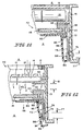
- Figs. 11 and 12 are top cross-sectional detail views of assembly 70 wherein Fig. 11 shows the assembly prior to an explosion, and Fig. 12 shows the assembly during an explosion. It is notable that, prior to the explosion, as shown in Fig. 11 , for this embodiment, stop 75 is not positioned within catch 94 of J-brackets 74. A space 77 exists between stop 75 and catch 94. This allows for ease of installation of T-bracket 72 wherein protrusion 96, stop 75, and brace 80 can he attached to frame 10 and fit blast window 18 into place without having to fit stop 75 into catch 94 first. During an explosion, as shown in Fig. 12 , and similar to what happens in assembly 2, debris from outer window 12 engages blinds 14.
- assembly 70 has a magnet 22, or similar attachment, that disengages from bracket 16, creating a space 81, which allows the blast force 50 to escape about the periphery of blast window 18 and into die interior 6.
- the T-bracket 72 engages blast window 18 by the blast force 50, causing both blast window 18 and T-bracket 72 to move in direction 98.
- stop 75 engages catch 94 to assist in bracing blast window 18.
Landscapes
- Engineering & Computer Science (AREA)
- Civil Engineering (AREA)
- Structural Engineering (AREA)
- Wing Frames And Configurations (AREA)
- Securing Of Glass Panes Or The Like (AREA)
- Window Of Vehicle (AREA)
Abstract
Claims (20)
- Ensemble (2, 70) de fenêtre résistant à la déflagration, comprenant :une fenêtre (18) anti-déflagration montée à l'intérieur d'une ouverture (4) ayant au moins une paroi ; etune première console comprenant une entretoise (28, 80) située de façon adjacente à la fenêtre (18) anti-déflagration,caractérisé en ce que : la première console comprend ;
une butée (30, 75) située de façon adjacente à la paroi ; et en ce que l'ensemble (2, 70) comprend ;
une deuxième console située de façon adjacente à la paroi et conçue pour recevoir la butée (30, 75) ;
dans lequel, pendant une explosion, la force de déflagration (50) provoquée par celle-ci conduit la fenêtre (18) anti-déflagration à entrer en prise avec l'entretoise (28, 80) de la première console pour amener la butée (30, 75) de celle-ci à être reçue par la deuxième console. - Ensemble (2, 70) de fenêtre résistant à la déflagration selon la revendication 1, dans lequel, pendant l'explosion, la fenêtre (18) anti-déflagration se déforme de façon arquée pour répartir la force de déflagration (50) sur la fenêtre (18) anti-déflagration.
- Ensemble (2, 70) de fenêtre résistant à la déflagration selon la revendication 1, dans lequel, pendant une explosion, quand la fenêtre (18) anti-déflagration entre en contact avec l'entretoise (28, 80), un espace est créé entre la paroi et la fenêtre (18) anti-déflagration pour permettre à la pression provoquée par la force de déflagration (50) de l'explosion de passer au milieu.
- Ensemble (2, 70) de fenêtre résistant à la déflagration selon la revendication 1, dans lequel il existe une encoche (42) entre la première console et la fenêtre (18) anti-déflagration avant l'explosion.
- Ensemble (2, 70) de fenêtre résistant à la déflagration selon la revendication 1, dans lequel la fenêtre (18) anti-déflagration comprend également un châssis (20) situé à sa périphérie.
- Ensemble (2, 70) de fenêtre résistant à la déflagration selon la revendication 5, dans lequel, pendant l'explosion, une portion du châssis (20) entre en prise avec l'entretoise (28, 80) de la première console.
- Ensemble (2, 70) de fenêtre résistant à la déflagration selon la revendication 1, comprenant également une fenêtre extérieure (12) montée à l'intérieur de l'ouverture (4) et faisant face à la fenêtre (18) anti-déflagration en face de la première et de la deuxième console.
- Ensemble (2, 70) de fenêtre résistant à la déflagration selon la revendication 7, comprenant également un store (14) situé à l'intérieur de l'ouverture et positionné entre la fenêtre extérieure (12) et la fenêtre (18) anti-déflagration.
- Ensemble (2, 70) de fenêtre résistant à la déflagration selon la revendication 1, dans lequel la fenêtre (18) anti-déflagration est une contre-fenêtre.
- Ensemble (2, 70) de fenêtre résistant à la déflagration selon la revendication 1, dans lequel la fenêtre (18) anti-déflagration est feuilletée avec un film.
- Ensemble (2, 70) de fenêtre résistant à la déflagration, comprenant :une fenêtre (18) anti-déflagration ayant une face et une extrémité ;dans lequel l'extrémité de la fenêtre (18) anti-déflagration est montée à l'intérieur d'une ouverture (4) ayant au moins une paroi latérale ; et
une première console ayant une longueur et une entretoise (28, 80) située de façon adjacente à la face de la fenêtre (18) anti-déflagration,
caractérisé en ce que la première console comprend ;
une butée (30, 75) qui s'étend à partir de l'entretoise (28, 80) et située de façon généralement perpendiculaire à la paroi latérale et de façon adjacente à cette dernière, et une saillie (26) s'étendant à partir de l'entretoise (28, 80) et située de façon adjacente à l'extrémité de la fenêtre (18) anti-déflagration ;
dans lequel l'entretoise (28, 80), la butée (30, 75) et la saillie (26, 94) s'étendent sur au moins une portion de la longueur de la première console ; et en ce que l'ensemble comprend également ;
une deuxième console ayant une longueur, et ayant une rainure avec une ouverture qui fait face à la butée de la première console pour recevoir la butée (30, 75) pendant une explosion. - Ensemble (2, 70) de fenêtre résistant à la déflagration selon la revendication 11, dans lequel la pression provoquée par l'explosion conduit la fenêtre (18) anti-déflagration à entrer en prise avec l'entretoise (28, 80) de la première console pour amener la butée (30, 75) de celle-ci à entrer en contact avec la rainure de la deuxième console.
- Ensemble (2, 70) de fenêtre résistant à la déflagration selon la revendication 11, dans lequel une encoche (42) est située entre l'entretoise (28) de la première console et la fenêtre (18) anti-déflagration.
- Ensemble (2, 70) de fenêtre résistant à la déflagration selon la revendication 12, dans lequel l'entretoise (80) de la première console vient buter contre la fenêtre (18) anti-déflagration.
- Ensemble (2, 70) de fenêtre résistant à la déflagration selon la revendication 12, comprenant également une troisième console (16) qui est attachée de façon amovible à la fenêtre (18) anti-déflagration, dans lequel la fenêtre (18) anti-déflagration se sépare de la troisième console (16) pendant une explosion.
- Ensemble (2, 70) de fenêtre résistant à la déflagration selon la revendication 15, dans lequel la longueur de la première console s'étend le long d'une trajectoire arquée.
- Ensemble (2, 70) de fenêtre résistant à la déflagration selon la revendication 11, dans lequel la longueur de la deuxième console s'étend le long d'une trajectoire arquée.
- Ensemble (2, 70) de fenêtre résistant à la déflagration selon la revendication 16, dans lequel la fenêtre se déforme le long de la trajectoire arquée de la première console pendant l'explosion.
- Ensemble (2, 70) de fenêtre résistant à la déflagration selon la revendication 14, dans lequel la butée (75) de la première console comporte une encoche (82) qui reçoit et permet le mouvement de la première console par rapport à un élément stationnaire pendant une explosion.
- Ensemble (2, 70) de fenêtre résistant à la déflagration, comprenant :une fenêtre (18) anti-déflagration montée à l'intérieur d'une ouverture (4),une console en T (24, 72) située de façon adjacente à la fenêtre (18) anti-déflagration et ayant des moyens pour maintenir la fenêtre (18) anti-déflagration pendant une explosion ; etune console en J (32, 74) située de façon adjacente à la console en T (24, 72) et conçue pour recevoir cette dernière afin de maintenir la fenêtre (18) anti-déflagration pendant l'explosion.
Applications Claiming Priority (11)
| Application Number | Priority Date | Filing Date | Title |
|---|---|---|---|
| US37472102P | 2002-04-23 | 2002-04-23 | |
| US374721P | 2002-04-23 | ||
| US38272702P | 2002-05-23 | 2002-05-23 | |
| US382727P | 2002-05-23 | ||
| US39605902P | 2002-07-16 | 2002-07-16 | |
| US396059P | 2002-07-16 | ||
| US40956002P | 2002-09-10 | 2002-09-10 | |
| US409560P | 2002-09-10 | ||
| US41114802P | 2002-09-16 | 2002-09-16 | |
| US411148P | 2002-09-16 | ||
| PCT/US2003/012394 WO2003091526A2 (fr) | 2002-04-23 | 2003-04-21 | Fenetre resistant au souffle |
Publications (3)
| Publication Number | Publication Date |
|---|---|
| EP1501998A2 EP1501998A2 (fr) | 2005-02-02 |
| EP1501998A4 EP1501998A4 (fr) | 2006-06-14 |
| EP1501998B1 true EP1501998B1 (fr) | 2009-07-15 |
Family
ID=29273891
Family Applications (1)
| Application Number | Title | Priority Date | Filing Date |
|---|---|---|---|
| EP03728476A Expired - Lifetime EP1501998B1 (fr) | 2002-04-23 | 2003-04-21 | Fenêtre à résistance améliorée aux explosions |
Country Status (5)
| Country | Link |
|---|---|
| US (2) | US7383666B2 (fr) |
| EP (1) | EP1501998B1 (fr) |
| AU (1) | AU2003234168A1 (fr) |
| DE (1) | DE60328377D1 (fr) |
| WO (1) | WO2003091526A2 (fr) |
Families Citing this family (26)
| Publication number | Priority date | Publication date | Assignee | Title |
|---|---|---|---|---|
| US6873920B2 (en) * | 2001-10-15 | 2005-03-29 | Air Liquide Process And Construction, Inc. | Oxygen fire and blast fragment barriers |
| EP1501998B1 (fr) * | 2002-04-23 | 2009-07-15 | Therm-O-Lite, Inc. | Fenêtre à résistance améliorée aux explosions |
| US8590227B2 (en) | 2002-04-23 | 2013-11-26 | Donald L. Coddens | Blast-resistant window |
| WO2006020611A2 (fr) * | 2004-08-13 | 2006-02-23 | Glasslock, Inc. | Systeme d'accrochage de fragment de verre d'installation apres-coup |
| US20060080936A1 (en) * | 2004-10-18 | 2006-04-20 | Dooley David M | Method of manufacturing reinforced structures |
| DE102006005509A1 (de) * | 2006-02-07 | 2007-08-30 | Fraunhofer-Gesellschaft zur Förderung der angewandten Forschung e.V. | Splitterschutz mit optischer und thermischer Funktionalität |
| KR100814016B1 (ko) * | 2006-06-29 | 2008-03-14 | 에멕 모드차이 | 폭발 폭풍의 영향을 줄이는 창구 설치물 조립체 및 그 방법 |
| GB2443826A (en) * | 2006-11-16 | 2008-05-21 | Brian Malcom Wilkins | Window and combined defence shutter and blind |
| US8898966B2 (en) * | 2006-12-05 | 2014-12-02 | Oran Safety Glass Ltd. | Blast and impact resistant window pane systems |
| US20100281783A1 (en) * | 2009-05-11 | 2010-11-11 | Patrick Harrington | System and apparatus for shielding property |
| GB0922689D0 (en) * | 2009-12-30 | 2010-02-17 | Wilkins Brian M | Security screen |
| US8365492B2 (en) * | 2010-02-08 | 2013-02-05 | Glasslock, Inc. | Blast protection window retention system |
| US9827521B2 (en) * | 2011-08-09 | 2017-11-28 | The Newway Company | Assembly, kit and method for securing a covering to an air intake including magnetic connecting inserts |
| US8863440B1 (en) * | 2013-05-21 | 2014-10-21 | Therm-O-Lite, Inc. | Force-resistant panel |
| WO2022212726A1 (fr) | 2021-04-01 | 2022-10-06 | Adrain John B | Procédé de fabrication de stratifié anti-balistique pour produits |
| US10151566B2 (en) * | 2013-09-03 | 2018-12-11 | John B. Adrain | Bullet proof blinds |
| US10473437B2 (en) | 2013-09-03 | 2019-11-12 | John B. Adrain | Bullet proof blinds |
| US11561070B2 (en) | 2013-09-03 | 2023-01-24 | Disruptive Resources, Llc | Bullet proof barriers |
| US10801815B2 (en) * | 2013-09-03 | 2020-10-13 | John B. Adrain | Bullet proof blinds |
| US9791245B1 (en) * | 2013-12-18 | 2017-10-17 | Michael John Lamore | Building protection barrier system |
| US9758982B2 (en) * | 2015-12-10 | 2017-09-12 | Smart Vent Products, Inc. | Flood vent having a panel |
| US10260229B2 (en) * | 2017-04-12 | 2019-04-16 | Southern Comfort Shelters, Inc. | Blast resistant shelter and method of assembly |
| GB201808482D0 (en) * | 2018-05-23 | 2018-07-11 | Wilkins Brian Malcom | Safety screen |
| US11733005B2 (en) | 2019-08-28 | 2023-08-22 | Disruptive Defenses, Llc | Anti-ballistic barriers |
| US12012801B2 (en) * | 2019-09-30 | 2024-06-18 | United States Of America As Represented By The Secretary Of The Army | Hardened operable window systems and methods |
| US11286711B2 (en) * | 2019-09-30 | 2022-03-29 | United States Of America As Represented By The Secretary Of The Army | Hardened compression frame systems and methods |
Family Cites Families (30)
| Publication number | Priority date | Publication date | Assignee | Title |
|---|---|---|---|---|
| DE354173C (de) | 1917-03-06 | 1922-06-02 | Heinrich Heimann Dipl Ing Dr | Ofen zur Verarbeitung von Erzen u. dgl. |
| US2721157A (en) * | 1953-01-05 | 1955-10-18 | Pittsburgh Plate Glass Co | Explosion resisting window |
| FR1399071A (fr) * | 1964-06-17 | 1965-05-14 | Corning Glass Works | Structure de fenêtre propre à résister à des efforts importants tels qu'exercés par de grands vents |
| US3624238A (en) | 1969-03-24 | 1971-11-30 | Binswanger Glass Co | Laminated transparent bullet resisting structure |
| US4312903A (en) | 1980-03-05 | 1982-01-26 | General Electric Company | Impact resistant double glazed structure |
| DE8321690U1 (de) * | 1983-07-28 | 1984-02-02 | Sälzer, Heinrich, 3550 Marburg | Sprengwirkungshemmendes glasbauelement |
| DE3432021A1 (de) | 1984-08-31 | 1986-03-13 | Heinrich 3550 Marburg Sälzer | Sicherheitsfenster oder -tuer |
| DE3545173A1 (de) * | 1985-12-20 | 1987-06-25 | Siegfried Bauer | Sprengwirkungshemmend ausgestaltete fensteranordnung |
| US5368904A (en) * | 1988-07-18 | 1994-11-29 | Stephinson; William P. | Bullet resistant glass |
| IL88384A (en) | 1988-11-15 | 1993-07-08 | Eagle | Protective ballistic panel |
| DE9310957U1 (de) * | 1993-07-22 | 1993-09-23 | Vegla Vereinigte Glaswerke Gmbh, 52066 Aachen | Panzerglasscheibe fuer kraftfahrzeuge |
| US5645940A (en) * | 1995-05-31 | 1997-07-08 | Teddington, Jr., Deceased; Charles J. | Shatter-resistant glass having polyester layers |
| US5834124C1 (en) * | 1996-12-27 | 2001-11-27 | Pease Ind Inc | Impact resistant laminated glass windows |
| US6108999A (en) * | 1997-02-10 | 2000-08-29 | General Electric Co. | Window and glazing for a window |
| US6010758A (en) * | 1997-06-12 | 2000-01-04 | Anglin, Jr.; Richard L. | Shrapnel mitigation system |
| FR2764841B1 (fr) * | 1997-06-18 | 1999-07-16 | Saint Gobain Vitrage | Vitrage blinde, notamment lateral fixe ou mobile pour vehicule automobile |
| US6057029A (en) * | 1997-09-16 | 2000-05-02 | Virginia Iron And Metal Co. | Protective window shield for blast mitigation |
| IL123980A (en) * | 1998-04-07 | 2000-10-31 | Arpal Aluminum Ltd | Blast resistant window framework and elements thereof |
| IL127265A (en) * | 1998-11-26 | 2001-03-19 | Arpal Aluminium Ltd | Blast resistant framework |
| DE29904378U1 (de) | 1999-03-10 | 1999-05-12 | Steinbach & Vollmann GmbH & Co., 42579 Heiligenhaus | Beschlag für Türen, Fenster u.dgl. Schließelemente |
| US6494000B1 (en) | 1999-03-11 | 2002-12-17 | Arpel Aluminum Ltd. | Resistant window systems |
| IL128936A (en) | 1999-03-11 | 2004-02-19 | Arpal Aluminium Ltd | Shade-resistant window |
| FR2795365B1 (fr) * | 1999-06-25 | 2002-07-12 | Saint Gobain Vitrage | Vitrage feuillete blinde, en particulier pour vehicules automobiles |
| US6333085B1 (en) | 1999-11-08 | 2001-12-25 | Arpal Aluminum, Ltd. | Resistant window systems |
| US6509071B1 (en) | 2000-02-09 | 2003-01-21 | Arpal Aluminum Ltd. | Reinforced window systems |
| US6385924B1 (en) | 2000-05-25 | 2002-05-14 | Arpal Aluminum, Ltd. | Reinforced window system |
| US6817952B2 (en) * | 2001-07-31 | 2004-11-16 | Clear Defense Sports & Athletic Laminates, L.L.C. | Glass laminate system for hockey rinks |
| US6715245B2 (en) * | 2002-04-03 | 2004-04-06 | Signature Door Co., Inc. | Impact resistant pane and mounting |
| EP1501998B1 (fr) * | 2002-04-23 | 2009-07-15 | Therm-O-Lite, Inc. | Fenêtre à résistance améliorée aux explosions |
| DE10220832C1 (de) * | 2002-05-08 | 2003-08-14 | Saelzer Sicherheitstechnik | Gebäudeabschluss in sprengwirkungshemmender Ausführung |
-
2003
- 2003-04-21 EP EP03728476A patent/EP1501998B1/fr not_active Expired - Lifetime
- 2003-04-21 DE DE60328377T patent/DE60328377D1/de not_active Expired - Fee Related
- 2003-04-21 AU AU2003234168A patent/AU2003234168A1/en not_active Abandoned
- 2003-04-21 WO PCT/US2003/012394 patent/WO2003091526A2/fr not_active Ceased
- 2003-04-22 US US10/420,306 patent/US7383666B2/en not_active Expired - Fee Related
-
2008
- 2008-06-09 US US12/135,770 patent/US8151525B2/en not_active Expired - Fee Related
Also Published As
| Publication number | Publication date |
|---|---|
| US8151525B2 (en) | 2012-04-10 |
| US7383666B2 (en) | 2008-06-10 |
| DE60328377D1 (de) | 2009-08-27 |
| US20110056365A1 (en) | 2011-03-10 |
| AU2003234168A8 (en) | 2003-11-10 |
| AU2003234168A1 (en) | 2003-11-10 |
| US20040025453A1 (en) | 2004-02-12 |
| WO2003091526A2 (fr) | 2003-11-06 |
| EP1501998A4 (fr) | 2006-06-14 |
| WO2003091526A3 (fr) | 2004-09-10 |
| EP1501998A2 (fr) | 2005-02-02 |
Similar Documents
| Publication | Publication Date | Title |
|---|---|---|
| US8151525B2 (en) | Blast-resistant window | |
| US8590227B2 (en) | Blast-resistant window | |
| US7040062B2 (en) | Dismantable protective window | |
| US6088979A (en) | Frame for supporting an auxiliary glazing and method for installing the improved frame | |
| US6367210B1 (en) | Apparatus and method for securing a pane against impact | |
| US6530184B1 (en) | Blast resistant framework | |
| KR101391818B1 (ko) | 안전 요소를 구비하는 창유리 | |
| US9790735B2 (en) | Protective additional glazing systems, apparatus and methods for structural openings | |
| EP2004944B1 (fr) | Element a absorption d'energie pour ouvertures dans un mur et procedes d'utilisation pour celui-ci | |
| US6581342B1 (en) | Blast protective window | |
| WO1998059143A1 (fr) | Procede et appareil pour monter en bordure une pellicule plastique de securite dans un cadre de fenetre | |
| US7775003B2 (en) | Apparatus for securing an impact resistant window to a window frame | |
| US20060080894A1 (en) | Frame/filling combination | |
| EP1212503B1 (fr) | Element de blocage | |
| US9080371B2 (en) | Security screen | |
| US4972639A (en) | Security window | |
| GB2296020A (en) | Blast-resistant mounting for, e.g. a window | |
| GB2489422A (en) | Security window assembly | |
| EP1790815B1 (fr) | Système de fenêtre et/ou facade | |
| GB2597899A (en) | Anchoring apparatus | |
| HK1027850B (en) | Apparatus and method for securing a pane against impact | |
| JP3800341B2 (ja) | ルーバーガラス | |
| Coltharp et al. | Blast retrofit research and development: protection for walls and windows. | |
| WO2007053903A1 (fr) | Chassis pour ecran de securite |
Legal Events
| Date | Code | Title | Description |
|---|---|---|---|
| PUAI | Public reference made under article 153(3) epc to a published international application that has entered the european phase |
Free format text: ORIGINAL CODE: 0009012 |
|
| 17P | Request for examination filed |
Effective date: 20041119 |
|
| AK | Designated contracting states |
Kind code of ref document: A2 Designated state(s): AT BE BG CH CY CZ DE DK EE ES FI FR GB GR HU IE IT LI LU MC NL PT RO SE SI SK TR |
|
| AX | Request for extension of the european patent |
Extension state: AL LT LV MK |
|
| A4 | Supplementary search report drawn up and despatched |
Effective date: 20060512 |
|
| RIC1 | Information provided on ipc code assigned before grant |
Ipc: E06B 5/12 20060101ALI20060509BHEP Ipc: E06B 3/01 20060101AFI20041126BHEP |
|
| 17Q | First examination report despatched |
Effective date: 20080701 |
|
| GRAP | Despatch of communication of intention to grant a patent |
Free format text: ORIGINAL CODE: EPIDOSNIGR1 |
|
| RIC1 | Information provided on ipc code assigned before grant |
Ipc: E06B 5/12 20060101AFI20090105BHEP |
|
| RTI1 | Title (correction) |
Free format text: WINDOW WITH ENHANCED RESISTANCE TO EXPLOSION BLAST FORCES |
|
| GRAS | Grant fee paid |
Free format text: ORIGINAL CODE: EPIDOSNIGR3 |
|
| GRAA | (expected) grant |
Free format text: ORIGINAL CODE: 0009210 |
|
| AK | Designated contracting states |
Kind code of ref document: B1 Designated state(s): AT BE BG CH CY CZ DE DK EE ES FI FR GB GR HU IE IT LI LU MC NL PT RO SE SI SK TR |
|
| REG | Reference to a national code |
Ref country code: CH Ref legal event code: EP Ref country code: GB Ref legal event code: FG4D |
|
| REG | Reference to a national code |
Ref country code: IE Ref legal event code: FG4D |
|
| REF | Corresponds to: |
Ref document number: 60328377 Country of ref document: DE Date of ref document: 20090827 Kind code of ref document: P |
|
| NLV1 | Nl: lapsed or annulled due to failure to fulfill the requirements of art. 29p and 29m of the patents act | ||
| PG25 | Lapsed in a contracting state [announced via postgrant information from national office to epo] |
Ref country code: AT Free format text: LAPSE BECAUSE OF FAILURE TO SUBMIT A TRANSLATION OF THE DESCRIPTION OR TO PAY THE FEE WITHIN THE PRESCRIBED TIME-LIMIT Effective date: 20090715 Ref country code: ES Free format text: LAPSE BECAUSE OF FAILURE TO SUBMIT A TRANSLATION OF THE DESCRIPTION OR TO PAY THE FEE WITHIN THE PRESCRIBED TIME-LIMIT Effective date: 20091026 Ref country code: SE Free format text: LAPSE BECAUSE OF FAILURE TO SUBMIT A TRANSLATION OF THE DESCRIPTION OR TO PAY THE FEE WITHIN THE PRESCRIBED TIME-LIMIT Effective date: 20090715 Ref country code: FI Free format text: LAPSE BECAUSE OF FAILURE TO SUBMIT A TRANSLATION OF THE DESCRIPTION OR TO PAY THE FEE WITHIN THE PRESCRIBED TIME-LIMIT Effective date: 20090715 |
|
| PG25 | Lapsed in a contracting state [announced via postgrant information from national office to epo] |
Ref country code: SI Free format text: LAPSE BECAUSE OF FAILURE TO SUBMIT A TRANSLATION OF THE DESCRIPTION OR TO PAY THE FEE WITHIN THE PRESCRIBED TIME-LIMIT Effective date: 20090715 Ref country code: NL Free format text: LAPSE BECAUSE OF FAILURE TO SUBMIT A TRANSLATION OF THE DESCRIPTION OR TO PAY THE FEE WITHIN THE PRESCRIBED TIME-LIMIT Effective date: 20090715 |
|
| PG25 | Lapsed in a contracting state [announced via postgrant information from national office to epo] |
Ref country code: BG Free format text: LAPSE BECAUSE OF FAILURE TO SUBMIT A TRANSLATION OF THE DESCRIPTION OR TO PAY THE FEE WITHIN THE PRESCRIBED TIME-LIMIT Effective date: 20091015 Ref country code: PT Free format text: LAPSE BECAUSE OF FAILURE TO SUBMIT A TRANSLATION OF THE DESCRIPTION OR TO PAY THE FEE WITHIN THE PRESCRIBED TIME-LIMIT Effective date: 20091115 |
|
| PG25 | Lapsed in a contracting state [announced via postgrant information from national office to epo] |
Ref country code: CZ Free format text: LAPSE BECAUSE OF FAILURE TO SUBMIT A TRANSLATION OF THE DESCRIPTION OR TO PAY THE FEE WITHIN THE PRESCRIBED TIME-LIMIT Effective date: 20090715 Ref country code: RO Free format text: LAPSE BECAUSE OF FAILURE TO SUBMIT A TRANSLATION OF THE DESCRIPTION OR TO PAY THE FEE WITHIN THE PRESCRIBED TIME-LIMIT Effective date: 20090715 Ref country code: EE Free format text: LAPSE BECAUSE OF FAILURE TO SUBMIT A TRANSLATION OF THE DESCRIPTION OR TO PAY THE FEE WITHIN THE PRESCRIBED TIME-LIMIT Effective date: 20090715 Ref country code: DK Free format text: LAPSE BECAUSE OF FAILURE TO SUBMIT A TRANSLATION OF THE DESCRIPTION OR TO PAY THE FEE WITHIN THE PRESCRIBED TIME-LIMIT Effective date: 20090715 |
|
| PLBE | No opposition filed within time limit |
Free format text: ORIGINAL CODE: 0009261 |
|
| STAA | Information on the status of an ep patent application or granted ep patent |
Free format text: STATUS: NO OPPOSITION FILED WITHIN TIME LIMIT |
|
| PG25 | Lapsed in a contracting state [announced via postgrant information from national office to epo] |
Ref country code: SK Free format text: LAPSE BECAUSE OF FAILURE TO SUBMIT A TRANSLATION OF THE DESCRIPTION OR TO PAY THE FEE WITHIN THE PRESCRIBED TIME-LIMIT Effective date: 20090715 Ref country code: BE Free format text: LAPSE BECAUSE OF FAILURE TO SUBMIT A TRANSLATION OF THE DESCRIPTION OR TO PAY THE FEE WITHIN THE PRESCRIBED TIME-LIMIT Effective date: 20090715 |
|
| 26N | No opposition filed |
Effective date: 20100416 |
|
| PG25 | Lapsed in a contracting state [announced via postgrant information from national office to epo] |
Ref country code: GR Free format text: LAPSE BECAUSE OF FAILURE TO SUBMIT A TRANSLATION OF THE DESCRIPTION OR TO PAY THE FEE WITHIN THE PRESCRIBED TIME-LIMIT Effective date: 20091016 |
|
| PG25 | Lapsed in a contracting state [announced via postgrant information from national office to epo] |
Ref country code: MC Free format text: LAPSE BECAUSE OF NON-PAYMENT OF DUE FEES Effective date: 20100430 |
|
| REG | Reference to a national code |
Ref country code: CH Ref legal event code: PL |
|
| REG | Reference to a national code |
Ref country code: FR Ref legal event code: ST Effective date: 20101230 |
|
| PG25 | Lapsed in a contracting state [announced via postgrant information from national office to epo] |
Ref country code: IE Free format text: LAPSE BECAUSE OF NON-PAYMENT OF DUE FEES Effective date: 20100421 |
|
| PG25 | Lapsed in a contracting state [announced via postgrant information from national office to epo] |
Ref country code: CH Free format text: LAPSE BECAUSE OF NON-PAYMENT OF DUE FEES Effective date: 20100430 Ref country code: LI Free format text: LAPSE BECAUSE OF NON-PAYMENT OF DUE FEES Effective date: 20100430 Ref country code: DE Free format text: LAPSE BECAUSE OF NON-PAYMENT OF DUE FEES Effective date: 20101103 |
|
| PG25 | Lapsed in a contracting state [announced via postgrant information from national office to epo] |
Ref country code: IT Free format text: LAPSE BECAUSE OF FAILURE TO SUBMIT A TRANSLATION OF THE DESCRIPTION OR TO PAY THE FEE WITHIN THE PRESCRIBED TIME-LIMIT Effective date: 20090715 |
|
| PG25 | Lapsed in a contracting state [announced via postgrant information from national office to epo] |
Ref country code: FR Free format text: LAPSE BECAUSE OF NON-PAYMENT OF DUE FEES Effective date: 20100430 |
|
| PG25 | Lapsed in a contracting state [announced via postgrant information from national office to epo] |
Ref country code: CY Free format text: LAPSE BECAUSE OF FAILURE TO SUBMIT A TRANSLATION OF THE DESCRIPTION OR TO PAY THE FEE WITHIN THE PRESCRIBED TIME-LIMIT Effective date: 20090715 |
|
| PG25 | Lapsed in a contracting state [announced via postgrant information from national office to epo] |
Ref country code: HU Free format text: LAPSE BECAUSE OF FAILURE TO SUBMIT A TRANSLATION OF THE DESCRIPTION OR TO PAY THE FEE WITHIN THE PRESCRIBED TIME-LIMIT Effective date: 20100116 Ref country code: LU Free format text: LAPSE BECAUSE OF NON-PAYMENT OF DUE FEES Effective date: 20100421 |
|
| PG25 | Lapsed in a contracting state [announced via postgrant information from national office to epo] |
Ref country code: TR Free format text: LAPSE BECAUSE OF FAILURE TO SUBMIT A TRANSLATION OF THE DESCRIPTION OR TO PAY THE FEE WITHIN THE PRESCRIBED TIME-LIMIT Effective date: 20090715 |
|
| PGFP | Annual fee paid to national office [announced via postgrant information from national office to epo] |
Ref country code: GB Payment date: 20180427 Year of fee payment: 16 |
|
| GBPC | Gb: european patent ceased through non-payment of renewal fee |
Effective date: 20190421 |
|
| PG25 | Lapsed in a contracting state [announced via postgrant information from national office to epo] |
Ref country code: GB Free format text: LAPSE BECAUSE OF NON-PAYMENT OF DUE FEES Effective date: 20190421 |