EP1502520A1 - Dispositif de fermeture en particulier pour tiroirs de meuble - Google Patents
Dispositif de fermeture en particulier pour tiroirs de meuble Download PDFInfo
- Publication number
- EP1502520A1 EP1502520A1 EP03017409A EP03017409A EP1502520A1 EP 1502520 A1 EP1502520 A1 EP 1502520A1 EP 03017409 A EP03017409 A EP 03017409A EP 03017409 A EP03017409 A EP 03017409A EP 1502520 A1 EP1502520 A1 EP 1502520A1
- Authority
- EP
- European Patent Office
- Prior art keywords
- drawer
- spring
- driving pin
- automatic retraction
- housing
- Prior art date
- Legal status (The legal status is an assumption and is not a legal conclusion. Google has not performed a legal analysis and makes no representation as to the accuracy of the status listed.)
- Withdrawn
Links
Images






Classifications
-
- A—HUMAN NECESSITIES
- A47—FURNITURE; DOMESTIC ARTICLES OR APPLIANCES; COFFEE MILLS; SPICE MILLS; SUCTION CLEANERS IN GENERAL
- A47B—TABLES; DESKS; OFFICE FURNITURE; CABINETS; DRAWERS; GENERAL DETAILS OF FURNITURE
- A47B88/00—Drawers for tables, cabinets or like furniture; Guides for drawers
- A47B88/40—Sliding drawers; Slides or guides therefor
- A47B88/453—Actuated drawers
- A47B88/46—Actuated drawers operated by mechanically-stored energy, e.g. by springs
- A47B88/467—Actuated drawers operated by mechanically-stored energy, e.g. by springs self-closing
Definitions
- the invention relates to a locking device, in particular for furniture drawers according to the preamble of independent claims 1, 2, 13, 14.
- a closing device for drawers wherein the locking device a body side mounted, loaded by a spring Has a tilting element and a drawer side mounted driving pin.
- the guideway has a Straight rear section and a curved front section on which the Tilting element in a tilted position (locking position) leads and the driving pin releases.
- the object of the present invention is to provide a locking device, in particular for furniture drawers of the type described above and so to educate that the feeding and / or taking off the drawer in Furniture body seamless and with approximately continuous movement happens and false triggering can be prevented.
- Another task is one Locking device, especially for furniture drawers as compact, cost-effective and easy to install construction.
- the coupling device of the automatic retraction at least two relative to each other radially / transversely and / or axially to the feed direction the drawer has movable elements (in particular hooks), or a relative to the housing of the automatic retraction radially / transversely and / or axially to Feed direction of the drawer has movable element, wherein at least one with the plunger and / or the spring of automatic retraction rigid or articulated is connected and that these elements surround the driving pin lock in to pull in and / or pull out the drawer enable.
- the moving elements are lying (Hooks are preferred as movable elements) of the coupling device on one frontal or coat inside edge or lateral shell opening of the Housing of the automatic retraction latching on and the distance between the hooks is enough that the driving pin can drive in between when the drawer is closed.
- the coupling device If the coupling device is not intentionally closed, it can not mistakenly be drawn into the automatic retraction, because a stop the hook or an additional element holding the hooks in the open state.
- the driving pin is either a stop of a hook or a apply comparable element of the coupling device and thus the Close the hooks by locking the driving pin.
- the coupling device of the spring in the housing of the automatic insertion retracted (if a tension spring is present) or pressed (if a Compression spring is present) and the drawer completely closed.
- the opening of the drawer runs: the locked driver pin pulls the coupling device from the housing and the spring is biased. At the point where at least one hook of the coupling device from the housing protrudes or snaps into the opening of the housing, the hooks can laterally or radially / transversely to the longitudinal extent of the housing and / or longitudinally or axially to Remove longitudinal extension of the housing from each other (either by a Stop of a hook or by a comparable element). Finally, rest Both hooks on an edge or opening of the housing of the automatic retraction. The driving pin leaves the coupling device of the automatic retraction and the Drawer will be opened further. '
- the automatic intake can be used on the carcase rail, center rail as well be stored on the drawer rail and the driving pin immediately or indirectly mounted on one of the other rails.
- the driving pin can be guided guided on a guideway be so that the driving pin in the vertical axis and / or longitudinal axis and / or transverse axis of the rails is forced. This brings the advantage of that a more even movement takes place.
- the spring in the automatic retraction is a compression spring.
- the spring in the Automatic retraction is a plunger as a guide element for the spring in the automatic retraction intended.
- the spring is in the Automatic catch a tension spring.
- the coupling device has a Safety function on, with the driving pin in the automatic feed erroneously retracted coupling device can retrieve.
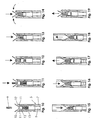
- FIG. 2 to 4 and Figs. 10 to 21 showing a symmetrical solution.
- the hooks 10 and 10 ' are preferably made of plastic, since they can deform for the safety function (see “safety function”).
- the wedge 12 with the tension-free compression spring 13 holds the hooks 10 and 10 'open on the front-side locking edge 11 of the housing 7 of the automatic retraction 5.
- the hooks 10 are rigidly connected to the plunger 9.
- the driving pin 6 has enough space therebetween when the drawer is closed.
- the wedge 12 When the driving pin 6, the wedge 12 is applied (Fig. 11), he pushes the wedge 12 to axially inward, ie, below in Fig. 12 until the wedge 12 meets the connection between the hook 10 / plunger 9, wherein the compression spring 13 and the Guide pin of the wedge 12 have space in a recess of the connection (Fig. 13). Then the hooks 10 begin to move radially / transversely to each other, ie to close. because the wedge 12 no longer blocks the hooks 10 ( Figure 14). The hooks 10 can thus slip into the interior of the housing 7 of the automatic retraction 5 (FIG. 15), without disturbing the continuous, uninterrupted movement of the entrainment pin 6 during the closing operation of the drawer. In the closed state of the drawer (FIG. 16), the connection between hook 10 / plunger 9 rests on the catch 14. The spring 8 is dead. The driving pin 6 is locked between the wedge 12 and the hooks 10 and 10 '.
- FIG. 5 and 6 and Figs. 22 to 33 A second example is shown in Figs. 5 and 6 and Figs. 22 to 33, which also show a symmetrical solution.
- the plate 15 this time controls the hooks 10 and 10 'via the bolts 22 of the hooks 10, which engage in the oblong holes 21 of the plate 15.
- the plate 15 is rigidly connected to the wedge 16.
- the wedge 16 is also rigidly connected to the plunger 9.
- the bolts 22 rest in the lower region of the elongated holes 21 and hold the hooks 10 open on the front-side latching edge 11.
- the driver pin 6 has enough space to move between the hooks 10, 10 'retract until it acts on the wedge 16 (Fig. 24). Then the driving pin 6 continues to move axially inwardly (down in Fig. 24, 25) and the bolts 22 are pushed onto the outside of the oblique slots 21, so that the hooks 10 thus slowly move towards each other and close (Fig. 25).
- the bolts 22 abut in the upper region of the oblong holes 21 (FIG. 26). Then the entire coupling device 23 can be retracted into the housing 7 of the automatic retraction 5 (FIG. 27).
- the plate 15 rests on the detent 14 and the spring 8 is de-energized (FIG. 28).
- the driving pin 6 first moves from the wedge 16 to the hook 10 (FIG. 29) and pulls the entire coupling device 23 out of the housing 7 (FIG. 30).
- the hooks 10 reach the frontal locking edge 11 of the housing 7, they can slowly open, because the bolts 22 can be pushed onto the inside of the oblique slots 21 (Fig. 31).
- the driving pin 6 has enough space to pass between them axially (upward in Fig. 32).
- the automatic retraction 5 then reaches its open position again (FIG. 33).
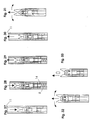
- FIGs. 7 and 8 show asymmetric solution.
- the hook 17 is rigidly connected to the plunger 9 and the hook 18 is free.
- the hook 17 In the open state, the hook 17 is located on the front side Locking edge 11 of the housing 7 and the hook 18 holds the hook 17 in his Position, because both hooks have a mutual oblique contact surface 27, wherein the stopper 24 presses on the edge 26 and the hook 18 on the edge 28th resting rests (Fig. 34).
- the driving pin 6 moves first up to the stop 24 of the hook 18 (Fig. 35). If the driving pin 6 continues enters the housing 7, the hook 18 tilts radially inward because of the stop 24 no longer presses on the edge 26 (Fig. 36).
- the driving pin 6 then moves along with the hook 18 until the axial stop of the hook 17 in the Housing 7, on which then the stop 24 of the hook 18 rests. Because the Contact surface 27 is oblique, the hook 18 can easily move away from the hook 17, but still being guided in a groove (FIG. 37). There is a small column between the contact surfaces 27 of the hooks 17, 18 results, the hook 17 of the Snap down edge 11 radially inwardly into the interior of the housing 7 down. In In this case, close the two hooks 17, 18 and lock the driving pin 6 between them (FIG. 38) and can then continue together with the Driving pin 6 are retracted into the housing 7 of the automatic retraction 5 (Fig. 39).
- FIGs. 9 and 49-57 show an asymmetric solution.
- the hook 17 is movably connected to the plunger 9 by means of the articulated connection 20, so that during axial movement of the plunger 9, the hook 17 can move / tilt relative to the plunger 9 radially or transversely to the longitudinal extension of the housing 7, but a nearly rigid Power transmission of the plunger 9 on the hook 17 in the axial direction (push or pull) is possible.
- the connecting element 20 is pivotally mounted on the hook 17 and the plunger 9, but ansich a rigid element and therefore in cooperation with the inner wall of the housing 7 axial tensile or shear forces almost rigidly transmitted from the plunger 9 on the hook 17 so that the hook moves axially and shifts radially / transversely / tilted and applies to the inner wall of the housing 7.
- the hook 18, however, is free and not fixed or hinged to the plunger 9 or the housing 7.
- the hook 17 lies with its head on the front-side latching edge 11 of the housing 7 and the axially further inward edge 31 of the hook 17 rests on the inner wall of the housing 7.
- the hook 18 rests with its locking head on the front-side locking edge 28 and with a further axially inner locking edge 19 on a projection on the inside of the housing 7.
- the further locking edge 19 of the hook 18 is approximately at the same axial depth In the housing 7, as the locking edge 11 of the hook 17.
- the driving pin 6 moves axially inwards along the radially inner side of the hook 18 (FIG. 50) as far as the stop 29, the hook 18 tipping radially inward on further axial movement into the housing 7 (FIG. 51).
- the hook 17 also tilts radially inwards, and the edge 32 of the hook 17, which is arranged at an angle to its edge 31, lies against the inside of the housing 7 and the driving pin 6 is thereby interposed the hooks 17, 18 locked ( Figure 52).
- the driving pin 6 then pushes the coupling device 23 further into the housing 7, the hooks 17 and 18 continue to tilt radially inward until they reach their final closed position.
- the stop 29 of the hook 18 then rests on the edge 33 of the hook 17, but the driving pin 6 does not rest on the stop 29 because it is locked in a higher position (FIG. 53).
- the driving pin 6 held by the stop 30 of the hook 17 pulls the entire coupling device 23 out of the housing 7 (FIG. 54) until the head-side radially outer stop 30 of the hook 17 reaches the locking edge 11 of the end face of the housing 7 and the hook 17 moves towards it tilted radially outside and rests on the locking edge 11.
- the hook 18 tilts radially inward to block the hook 17 so that it can not be pulled further axially out of the housing 7 (FIG. 55).
- the driving pin 6 can free from the stop 30 of the hook 17 and continues to the edge 34 of the hook 18 (Fig. 56).
- the driving pin 6 pulls the hook 18 axially outward until the hook 18 reaches the locking edge 28 and there can tip over radially and engage by frontal contact on the locking edge 28, and thus the driving pin 6 is released (Fig. 57).
- the open state is reached again.
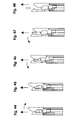
- FIGS. 58 to 62 A safety function is shown in FIGS. 58 to 62. If the coupling device in the housing 7 of the automatic retraction mechanism 5 was mistakenly retracted without a driving pin 6, the driving pin 6 is no longer engaged by the hooks 10 and the closing device would no longer function.
- the hooks 10 have a spring function (preferably made of plastic), but only the hook tip 36 and the hook rear part 37, but not the lower part of the hook head 38, otherwise otherwise could liberate the entrainment pin 6 itself during the opening process, just like him is locked in the return action.
- the coupling device 23 is retracted without driving pin 6 in the housing 7 of the automatic retraction 5. During the closing operation, the free driving pin 6 moves into the housing 7 (FIG.
- the hooks 10, 10 ', 17, 18 of the coupling device 23 lie on latching edges 11, 28, the in all figures 1-62 always at the end of the housing 7 of the automatic retraction 5 are arranged. You could imagine that the case 7 was built longer would be, and the locking edges 11, 28 would be in (not shown) lateral Openings introduced in the housing 7. In this case, the coupling device would be 23 even less tangible and an erroneous entry of the coupling device into Housing would be even less likely and thus the safety function is not necessary.
Landscapes
- Engineering & Computer Science (AREA)
- Mechanical Engineering (AREA)
- Drawers Of Furniture (AREA)
Priority Applications (3)
| Application Number | Priority Date | Filing Date | Title |
|---|---|---|---|
| EP03017409A EP1502520A1 (fr) | 2003-08-01 | 2003-08-01 | Dispositif de fermeture en particulier pour tiroirs de meuble |
| DE200420011009 DE202004011009U1 (de) | 2003-08-01 | 2004-07-14 | Schließvorrichtung, insbesondere für Möbelschubladen |
| AT0050904U AT7791U1 (de) | 2003-08-01 | 2004-07-19 | Schliessvorrichtung, insbesondere für möbelschubladen |
Applications Claiming Priority (1)
| Application Number | Priority Date | Filing Date | Title |
|---|---|---|---|
| EP03017409A EP1502520A1 (fr) | 2003-08-01 | 2003-08-01 | Dispositif de fermeture en particulier pour tiroirs de meuble |
Publications (1)
| Publication Number | Publication Date |
|---|---|
| EP1502520A1 true EP1502520A1 (fr) | 2005-02-02 |
Family
ID=33305766
Family Applications (1)
| Application Number | Title | Priority Date | Filing Date |
|---|---|---|---|
| EP03017409A Withdrawn EP1502520A1 (fr) | 2003-08-01 | 2003-08-01 | Dispositif de fermeture en particulier pour tiroirs de meuble |
Country Status (3)
| Country | Link |
|---|---|
| EP (1) | EP1502520A1 (fr) |
| AT (1) | AT7791U1 (fr) |
| DE (1) | DE202004011009U1 (fr) |
Cited By (4)
| Publication number | Priority date | Publication date | Assignee | Title |
|---|---|---|---|---|
| EP1817984A1 (fr) * | 2006-02-13 | 2007-08-15 | Grass GmbH | Dispositif pour influencer le mouvement des parties de meuble l'une par rapport à l'autre, en particulier pour des glissières pour tiroirs ainsi qu'une glissière pour tiroirs avec un tel dispositif |
| DE202007006825U1 (de) * | 2007-05-09 | 2008-09-11 | Paul Hettich Gmbh & Co. Kg | Rückholeinrichtung |
| CN104006105A (zh) * | 2014-05-27 | 2014-08-27 | 梁英姬 | 一种能调节阻尼力的大型橱柜用双向减震器及一种加装了双向减震器的橱柜 |
| CN108143377A (zh) * | 2017-12-30 | 2018-06-12 | 华帝股份有限公司 | 一种带回弹功能的导轨 |
Families Citing this family (4)
| Publication number | Priority date | Publication date | Assignee | Title |
|---|---|---|---|---|
| DE102008010768A1 (de) * | 2008-02-25 | 2009-08-27 | Heinrich J. Kesseböhmer KG | Möbel |
| DE102008010771B4 (de) | 2008-02-25 | 2018-03-01 | Kesseböhmer Holding Kg | Möbel |
| DE102010037826A1 (de) * | 2010-09-24 | 2012-03-29 | Paul Hettich Gmbh & Co. Kg | Selbsteinzugsvorrichtung für ein verschiebbares Möbelteil |
| RU203115U1 (ru) * | 2020-12-04 | 2021-03-22 | Общество с ограниченной ответственностью "БОЯРД" | Устройство автоматического выталкивания и фиксации подвижной части направляющей для выдвижного элемента мебели |
Citations (5)
| Publication number | Priority date | Publication date | Assignee | Title |
|---|---|---|---|---|
| DE4124512A1 (de) * | 1990-07-31 | 1992-02-06 | Blum Gmbh Julius | Schliessvorrichtung fuer schubladen |
| AT398521B (de) * | 1991-08-21 | 1994-12-27 | Fulterer Gmbh | Schliessvorrichtung für schubladenführungen |
| EP0391221B1 (fr) * | 1989-04-03 | 1995-09-13 | Julius Blum Gesellschaft m.b.H. | Dispositif pour fermer de tiroirs |
| US6340078B1 (en) * | 1998-08-06 | 2002-01-22 | Grass Gmbh | Braking device with closing servo control for movable cabinet/furniture parts |
| DE20218067U1 (de) * | 2002-11-19 | 2003-01-30 | Julius Blum Ges.m.b.H., Höchst | Schließ- und/oder Einzugsvorrichtung für bewegbare Möbelteile |
-
2003
- 2003-08-01 EP EP03017409A patent/EP1502520A1/fr not_active Withdrawn
-
2004
- 2004-07-14 DE DE200420011009 patent/DE202004011009U1/de not_active Expired - Lifetime
- 2004-07-19 AT AT0050904U patent/AT7791U1/de not_active IP Right Cessation
Patent Citations (5)
| Publication number | Priority date | Publication date | Assignee | Title |
|---|---|---|---|---|
| EP0391221B1 (fr) * | 1989-04-03 | 1995-09-13 | Julius Blum Gesellschaft m.b.H. | Dispositif pour fermer de tiroirs |
| DE4124512A1 (de) * | 1990-07-31 | 1992-02-06 | Blum Gmbh Julius | Schliessvorrichtung fuer schubladen |
| AT398521B (de) * | 1991-08-21 | 1994-12-27 | Fulterer Gmbh | Schliessvorrichtung für schubladenführungen |
| US6340078B1 (en) * | 1998-08-06 | 2002-01-22 | Grass Gmbh | Braking device with closing servo control for movable cabinet/furniture parts |
| DE20218067U1 (de) * | 2002-11-19 | 2003-01-30 | Julius Blum Ges.m.b.H., Höchst | Schließ- und/oder Einzugsvorrichtung für bewegbare Möbelteile |
Cited By (5)
| Publication number | Priority date | Publication date | Assignee | Title |
|---|---|---|---|---|
| EP1817984A1 (fr) * | 2006-02-13 | 2007-08-15 | Grass GmbH | Dispositif pour influencer le mouvement des parties de meuble l'une par rapport à l'autre, en particulier pour des glissières pour tiroirs ainsi qu'une glissière pour tiroirs avec un tel dispositif |
| DE202007006825U1 (de) * | 2007-05-09 | 2008-09-11 | Paul Hettich Gmbh & Co. Kg | Rückholeinrichtung |
| CN104006105A (zh) * | 2014-05-27 | 2014-08-27 | 梁英姬 | 一种能调节阻尼力的大型橱柜用双向减震器及一种加装了双向减震器的橱柜 |
| CN104006105B (zh) * | 2014-05-27 | 2020-03-06 | 梁英姬 | 一种能调节阻尼力的大型橱柜用双向减震器及一种加装了双向减震器的橱柜 |
| CN108143377A (zh) * | 2017-12-30 | 2018-06-12 | 华帝股份有限公司 | 一种带回弹功能的导轨 |
Also Published As
| Publication number | Publication date |
|---|---|
| AT7791U1 (de) | 2005-09-26 |
| DE202004011009U1 (de) | 2004-10-14 |
Similar Documents
| Publication | Publication Date | Title |
|---|---|---|
| EP3319482B1 (fr) | Dispositif d'entraînement destiné à un élément de meuble mobile | |
| EP0489122B1 (fr) | Dispositif automatique d'emboitement de guidages d'ouverture de tiroirs | |
| DE69209619T2 (de) | Zerlegbares schloss | |
| EP3320167B1 (fr) | Dispositif d'entraînement destiné à un élément de meuble mobile | |
| EP2983554B1 (fr) | Dispositif d'entraînement pour élément de meuble mobile | |
| EP1845821B1 (fr) | Dispositif de fermeture et d'ouverture de tiroirs | |
| EP1690473B1 (fr) | Système touch-latch pour des meubles avec des pièces de meuble qui bougent relativement les unes par rapport aux autres, en particulier des tiroirs de meubles, des portes de meubles ou des clapets de meubles | |
| EP3319483B1 (fr) | Dispositif d'entraînement destiné à un élément de meuble mobile | |
| DE19935120C2 (de) | Vorrichtung zum Öffnen und Schließen einer Schublade | |
| EP2373195B1 (fr) | Dispositif de rentrée automatique et glissière | |
| EP4082394B1 (fr) | Rail de charge pour un guidage d'extension de tiroir | |
| DE10256133A1 (de) | Kupplungsvorrichtung für ein in einer Ausziehführungsgarnitur integriertes Dämpfelement | |
| EP1374733A1 (fr) | Glissière pour tiroir | |
| DE202005002433U1 (de) | Touch-Latch System für Möbel mit zueinander relativ bewegbaren Möbelteilen, insbesondere Möbelschubladen, Möbeltüren oder Möbelklappe | |
| EP2210525B1 (fr) | Système de fermeture d'une partie de meuble amovible et meuble | |
| DE202009004955U1 (de) | Öffnungs- und Schließvorrichtung für ein Schubelement und Möbel | |
| EP3341545B1 (fr) | Dispositif de positionnement de deux portes coulissantes et meuble | |
| EP1500763A2 (fr) | Dispositif pour empêcher l'ouverture simultanée de tiroirs | |
| EP2630320B1 (fr) | Armature de tiroir pour relier un tiroir à une serrure centrale | |
| AT7791U1 (de) | Schliessvorrichtung, insbesondere für möbelschubladen | |
| DE20318929U1 (de) | Einzugsautomatik für Schubladen-Ausziehführungen | |
| EP2120646B1 (fr) | Corps de meuble muni d'une lèvre d'étanchéité et d'un éjecteur | |
| DE102022003805B4 (de) | Einzugs- und Auszugsvorrichtung mit bidirektionalen Einzugsvorrichtungen | |
| DE102019117593A1 (de) | Ausstoßvorrichtung für ein bewegbares Möbelteil | |
| EP1817984B1 (fr) | Dispositif pour influencer le mouvement des parties de meuble l'une par rapport à l'autre, en particulier pour des glissières pour tiroirs ainsi qu'une glissière pour tiroirs avec un tel dispositif |
Legal Events
| Date | Code | Title | Description |
|---|---|---|---|
| PUAI | Public reference made under article 153(3) epc to a published international application that has entered the european phase |
Free format text: ORIGINAL CODE: 0009012 |
|
| AK | Designated contracting states |
Kind code of ref document: A1 Designated state(s): AT BE BG CH CY CZ DE DK EE ES FI FR GB GR HU IE IT LI LU MC NL PT RO SE SI SK TR |
|
| AX | Request for extension of the european patent |
Extension state: AL LT LV MK |
|
| AKX | Designation fees paid | ||
| REG | Reference to a national code |
Ref country code: DE Ref legal event code: 8566 |
|
| STAA | Information on the status of an ep patent application or granted ep patent |
Free format text: STATUS: THE APPLICATION IS DEEMED TO BE WITHDRAWN |
|
| 18D | Application deemed to be withdrawn |
Effective date: 20050803 |