EP1502792A2 - Unité d'entrainement pour chariot de manutention - Google Patents
Unité d'entrainement pour chariot de manutention Download PDFInfo
- Publication number
- EP1502792A2 EP1502792A2 EP04017589A EP04017589A EP1502792A2 EP 1502792 A2 EP1502792 A2 EP 1502792A2 EP 04017589 A EP04017589 A EP 04017589A EP 04017589 A EP04017589 A EP 04017589A EP 1502792 A2 EP1502792 A2 EP 1502792A2
- Authority
- EP
- European Patent Office
- Prior art keywords
- drive unit
- transmission
- motor
- brake
- gear
- Prior art date
- Legal status (The legal status is an assumption and is not a legal conclusion. Google has not performed a legal analysis and makes no representation as to the accuracy of the status listed.)
- Granted
Links
- 230000005540 biological transmission Effects 0.000 claims description 23
- 239000004033 plastic Substances 0.000 claims description 3
- 239000013013 elastic material Substances 0.000 claims description 2
- 239000012783 reinforcing fiber Substances 0.000 claims 1
- 238000010276 construction Methods 0.000 abstract 1
- 230000008878 coupling Effects 0.000 abstract 1
- 238000010168 coupling process Methods 0.000 abstract 1
- 238000005859 coupling reaction Methods 0.000 abstract 1
- 230000008901 benefit Effects 0.000 description 7
- 238000012423 maintenance Methods 0.000 description 7
- 238000004519 manufacturing process Methods 0.000 description 5
- 230000009467 reduction Effects 0.000 description 4
- 230000002349 favourable effect Effects 0.000 description 2
- 238000009434 installation Methods 0.000 description 2
- 238000005096 rolling process Methods 0.000 description 2
- 238000003860 storage Methods 0.000 description 2
- 239000004952 Polyamide Substances 0.000 description 1
- 230000009286 beneficial effect Effects 0.000 description 1
- 230000000694 effects Effects 0.000 description 1
- 230000005284 excitation Effects 0.000 description 1
- 239000000463 material Substances 0.000 description 1
- 230000007246 mechanism Effects 0.000 description 1
- 238000000034 method Methods 0.000 description 1
- 229920002647 polyamide Polymers 0.000 description 1
- 230000036316 preload Effects 0.000 description 1
- 230000008569 process Effects 0.000 description 1
- 230000008439 repair process Effects 0.000 description 1
Images

Classifications
-
- B—PERFORMING OPERATIONS; TRANSPORTING
- B60—VEHICLES IN GENERAL
- B60K—ARRANGEMENT OR MOUNTING OF PROPULSION UNITS OR OF TRANSMISSIONS IN VEHICLES; ARRANGEMENT OR MOUNTING OF PLURAL DIVERSE PRIME-MOVERS IN VEHICLES; AUXILIARY DRIVES FOR VEHICLES; INSTRUMENTATION OR DASHBOARDS FOR VEHICLES; ARRANGEMENTS IN CONNECTION WITH COOLING, AIR INTAKE, GAS EXHAUST OR FUEL SUPPLY OF PROPULSION UNITS IN VEHICLES
- B60K7/00—Disposition of motor in, or adjacent to, traction wheel
- B60K7/0007—Disposition of motor in, or adjacent to, traction wheel the motor being electric
-
- B—PERFORMING OPERATIONS; TRANSPORTING
- B60—VEHICLES IN GENERAL
- B60K—ARRANGEMENT OR MOUNTING OF PROPULSION UNITS OR OF TRANSMISSIONS IN VEHICLES; ARRANGEMENT OR MOUNTING OF PLURAL DIVERSE PRIME-MOVERS IN VEHICLES; AUXILIARY DRIVES FOR VEHICLES; INSTRUMENTATION OR DASHBOARDS FOR VEHICLES; ARRANGEMENTS IN CONNECTION WITH COOLING, AIR INTAKE, GAS EXHAUST OR FUEL SUPPLY OF PROPULSION UNITS IN VEHICLES
- B60K17/00—Arrangement or mounting of transmissions in vehicles
- B60K17/04—Arrangement or mounting of transmissions in vehicles characterised by arrangement, location or kind of gearing
- B60K17/043—Transmission unit disposed in on near the vehicle wheel, or between the differential gear unit and the wheel
-
- B—PERFORMING OPERATIONS; TRANSPORTING
- B60—VEHICLES IN GENERAL
- B60K—ARRANGEMENT OR MOUNTING OF PROPULSION UNITS OR OF TRANSMISSIONS IN VEHICLES; ARRANGEMENT OR MOUNTING OF PLURAL DIVERSE PRIME-MOVERS IN VEHICLES; AUXILIARY DRIVES FOR VEHICLES; INSTRUMENTATION OR DASHBOARDS FOR VEHICLES; ARRANGEMENTS IN CONNECTION WITH COOLING, AIR INTAKE, GAS EXHAUST OR FUEL SUPPLY OF PROPULSION UNITS IN VEHICLES
- B60K7/00—Disposition of motor in, or adjacent to, traction wheel
- B60K2007/0046—Disposition of motor in, or adjacent to, traction wheel the motor moving together with the vehicle body, i.e. moving independently from the wheel axle
-
- B—PERFORMING OPERATIONS; TRANSPORTING
- B60—VEHICLES IN GENERAL
- B60K—ARRANGEMENT OR MOUNTING OF PROPULSION UNITS OR OF TRANSMISSIONS IN VEHICLES; ARRANGEMENT OR MOUNTING OF PLURAL DIVERSE PRIME-MOVERS IN VEHICLES; AUXILIARY DRIVES FOR VEHICLES; INSTRUMENTATION OR DASHBOARDS FOR VEHICLES; ARRANGEMENTS IN CONNECTION WITH COOLING, AIR INTAKE, GAS EXHAUST OR FUEL SUPPLY OF PROPULSION UNITS IN VEHICLES
- B60K7/00—Disposition of motor in, or adjacent to, traction wheel
- B60K2007/0061—Disposition of motor in, or adjacent to, traction wheel the motor axle being parallel to the wheel axle
-
- B—PERFORMING OPERATIONS; TRANSPORTING
- B60—VEHICLES IN GENERAL
- B60L—PROPULSION OF ELECTRICALLY-PROPELLED VEHICLES; SUPPLYING ELECTRIC POWER FOR AUXILIARY EQUIPMENT OF ELECTRICALLY-PROPELLED VEHICLES; ELECTRODYNAMIC BRAKE SYSTEMS FOR VEHICLES IN GENERAL; MAGNETIC SUSPENSION OR LEVITATION FOR VEHICLES; MONITORING OPERATING VARIABLES OF ELECTRICALLY-PROPELLED VEHICLES; ELECTRIC SAFETY DEVICES FOR ELECTRICALLY-PROPELLED VEHICLES
- B60L2220/00—Electrical machine types; Structures or applications thereof
- B60L2220/40—Electrical machine applications
- B60L2220/46—Wheel motors, i.e. motor connected to only one wheel
Definitions
- the present invention relates to a drive unit for industrial trucks, in particular for low and Stacker, according to the preamble of claim 1.
- Such trained as unicycle drive units are preferred for industrial trucks, in particular Pedestrian pallet trucks, low and stackers used, because of these applications a compact design is required is. It is the lowest possible focus of the Vehicle to aim at reducing the risk of tipping. In addition, the installation space is low to maneuverability of the vehicle. Due to the Fact that high driving forces and loads on one single driven impeller are transmitted Design components appropriately sized, in particular the housing and the gear stage.
- the transmission itself is designed in two stages, with the first gear with a spur gear toothing Drive motor is assigned while the second gear stage associated with a bevel gear to the impeller is.
- the two gear stages are by a in the housing mounted drive shaft connected to each other while the Impeller rotatably connected to the output side bevel gear is and an impeller rim and / or the bevel gear over Bearing elements relative to the housing pin or shaft journal are supported. Because both the spur gear and the bevel pinion in this case stuck on the drive shaft before installation can be mounted, the setting is a received good contact pattern and an advantageous bearing clearance of the spiral and circular bevel gear.
- the housing is integrally formed, wherein a first Opening to the drive motor and a second opening for Impeller is provided out. This should be the assembly and the disassembly of the unicycle are facilitated, wherein the first opening by a screw with the Slewing bearing inner ring after assembly and the second Opening by the bevel gear and a clampable cover be closed.
- a drive unit known for an industrial truck which has an electric motor, a two-stage gear, a drive wheel and a Has brake and pivotable about a vertical axis in the chassis of the industrial vehicle is receivable.
- the Drive member of the first gear stage is on the horizontal Output shaft of the electric motor arranged and the Output member of the first gear stage is on a in Gearbox mounted pinion shaft of the second gear stage arranged while the output member of the second Gear stage is arranged on an output shaft whose a drive wheel receiving end of the transmission housing protrudes; the electric motor is parallel to the axis arranged to the pinion shaft and the output shaft.
- the output member the first gear stage as a brake drum one Drum brake configured.
- the drive unit for this as a lifting truck trained industrial truck is with the chassis connected via a two-part pivot, which receives the inner ring of a pivot bearing, so that the gear housing around the vertical pivot axis is rotatably mounted on the chassis.
- a first Timing pulley On the output shaft of the electric motor is a first Timing pulley fitted, while a second toothed belt pulley rotatably and axially immovable on a in Gear housing and in a bearing plate by rolling bearings rotatably mounted pinion shaft is placed. Their pinion meshes with a spur gear, the non-rotatable and axially non-displaceable sitting on an output shaft by means of a Rolling bearing is rotatably mounted in the transmission housing. That the End remote end protrudes from the transmission housing and carries the drive wheel.
- the motor axis, the pivot axis and the axis of the drive wheel are in this case a vertical plane.
- the first pulley and the second pulley are connected with each other via a toothed belt, these parts form the first gear stage.
- the brake is integrated in the second pulley, the is formed by a pinion and the spur gear, wherein the Brake designed as a spring-loaded drum brake which is operated by the drawbar of the pallet truck can be.
- the object of the present invention is a drive unit to create an industrial truck that has a simplified structure, so that the production costs can be lowered, the assembly time is shortened and reduces the effort required for maintenance becomes.
- This new drive unit can be both a spur gear as well as a belt transmission and suitable especially as a drive for low and stackers.
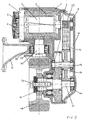
- the brake 3 is an electromagnetic in the two examples Brake, the magnetic body carrier 2 in one piece produced with the engine B-shield 1, which gives the advantage is achieved that the processing costs for two previously required separating surfaces account for.
- the in the two embodiments according to FIGS. 1 and 2 shown Brake 3 is due to their location easy to maintain because It is easily accessible and there is no brake actuation mechanism more necessary is the accessibility with special needs. For the maintenance of the brake only the vehicle fairing must to be opened, the drive unit does not need to be removed or dismantled.
- the electric motor 4 is in both variants as an AC motor executed, which in connection with the desired Purpose of the advantage is achieved that this due to the high speeds and low requirements built on the torque very compact and therefore cost can be produced.
- the stator 5 is included directly integrated in the transmission housing 6, for example pressed so that the previously required motor housing can be omitted.
- the motor shaft 7 and the drive pinion 8 are according to the invention integrally formed and thus also cheaper to produce.
- the motor shaft 7 is via bearings 9 in the gear housing cover 10, whereby the advantage is achieved that the bearing base for the meshing engagement of the first Gear stage in the embodiment of FIG. 1 low on the power transmission and the noise behavior effects; in the embodiment of FIG. 2 acts the bearing base for the meshing engagement of the first Gear stage favorable to the recording of the belt tension out.
- a spur gear 12 interposed from a plastic on the one hand bridges the gap and on the other hand in Advantageously limits the noise, especially the teeth in the first spur gear goes out, due to the high input speeds.
- One Intermediate plastic is particularly inexpensive to produce.
- a reinforced by preferably cast polyamide threads Belt 13 is provided, which has the advantage of a Own restraint, focusing on the required Belt tension sets independently, so always the optimal preload is available and thus the previously required clamping device deleted.
- the storage of the output shaft 15 is at the two Embodiments according to FIGS. 1 and 2 in contrast to the conventional bearings designed such that the broad camp base created by that the bearing 14 is inserted in the housing cover 10, a very favorable power consumption is ensured, in particular for high moments, and at the same time the meshing in the output stage 16, 17 is optimized, creating an improved Smooth running is achieved.
- the impeller 19 via a profile connection 18 connected to the output shaft 15, whereby, compared with the usual Verschraubungssectionn with flange and rim, which achieves advantage That will make the connection considerably less expensive is because the stock of the output shaft 15 easier to manufacture and process; it is also advantageous that in case of necessary maintenance and / or repair by loosening only one screw 20, the impeller 18 removed can be.
- the carrier 23, which connects the vehicle frame with the transmission, in a simple and cost-effective manner with the help of a threaded bolt 21 screwed into the transmission housing 6 becomes.
- This connection has a very beneficial effect Way to adjust the bias of the bearing 22 from and facilitates handling in the case of maintenance.
- a Bushing 24 made of an elastic material between the bearing 22 and the carrier 23 is used, whereby the big advantage is achieved that the vibration excitations or Vibration transmissions between vehicle and transmission are disconnected or interrupted, creating a significant Increasing the comfort of the entire vehicle for the operator achieved and the general noise behavior positively influenced.
- the inventively designed drive unit, the both a spur gear and a belt transmission can therefore have a variety of advantages with regard to the reduction of production costs, the Increasing smoothness, simplification of maintenance and the reduction of components.
Landscapes
- Engineering & Computer Science (AREA)
- Chemical & Material Sciences (AREA)
- Combustion & Propulsion (AREA)
- Transportation (AREA)
- Mechanical Engineering (AREA)
- Gear Transmission (AREA)
- Connection Of Motors, Electrical Generators, Mechanical Devices, And The Like (AREA)
- Retarders (AREA)
Applications Claiming Priority (2)
| Application Number | Priority Date | Filing Date | Title |
|---|---|---|---|
| DE10334449 | 2003-07-29 | ||
| DE2003134449 DE10334449A1 (de) | 2003-07-29 | 2003-07-29 | Antriebseinheit für Flurförderfahrzeuge |
Publications (3)
| Publication Number | Publication Date |
|---|---|
| EP1502792A2 true EP1502792A2 (fr) | 2005-02-02 |
| EP1502792A3 EP1502792A3 (fr) | 2006-06-14 |
| EP1502792B1 EP1502792B1 (fr) | 2007-08-29 |
Family
ID=33521438
Family Applications (1)
| Application Number | Title | Priority Date | Filing Date |
|---|---|---|---|
| EP04017589A Expired - Lifetime EP1502792B1 (fr) | 2003-07-29 | 2004-07-24 | Unité d'entrainement pour chariot de manutention |
Country Status (2)
| Country | Link |
|---|---|
| EP (1) | EP1502792B1 (fr) |
| DE (2) | DE10334449A1 (fr) |
Cited By (4)
| Publication number | Priority date | Publication date | Assignee | Title |
|---|---|---|---|---|
| DE102005017722A1 (de) * | 2005-04-15 | 2007-01-11 | Zf Friedrichshafen Ag | Antriebseinheit für ein Flurförderfahrzeug |
| WO2007036314A1 (fr) * | 2005-09-29 | 2007-04-05 | Zf Friedrichshafen Ag | Unite de commande |
| US10432065B2 (en) | 2016-03-30 | 2019-10-01 | Milwaukee Electric Tool Corporation | Brushless motor for a power tool |
| EP3760463A1 (fr) * | 2019-06-28 | 2021-01-06 | Kordel Antriebstechnik GmbH | Dispositif d'entraînement pour un chariot de manutention avec engrenage planétaire |
Families Citing this family (3)
| Publication number | Priority date | Publication date | Assignee | Title |
|---|---|---|---|---|
| DE102005041750B4 (de) * | 2005-09-02 | 2014-02-06 | Jungheinrich Aktiengesellschaft | Baukastensystem für Stirnradantriebe unterschiedlicher Leistung für Flurförderzeuge |
| DE102010045447B4 (de) | 2010-09-15 | 2020-02-06 | Sew-Eurodrive Gmbh & Co Kg | Elektromotor |
| DE102021209586B4 (de) | 2021-09-01 | 2023-06-29 | Zf Friedrichshafen Ag | Antriebseinheit für ein Flurförderfahrzeug sowie Flurförderfahrzeug mit der Antriebseinheit |
Citations (3)
| Publication number | Priority date | Publication date | Assignee | Title |
|---|---|---|---|---|
| DE3133027A1 (de) | 1981-08-20 | 1983-03-31 | Carl Hurth Maschinen- und Zahnradfabrik GmbH & Co, 8000 München | Getriebe fuer ein lenkbares antriebsrad eines fluorfoerderfahrzeugs |
| EP0400275A1 (fr) | 1989-06-01 | 1990-12-05 | HURTH Getriebe und Zahnräder G.m.b.H. | Unité de propulsion pour un chariot de manutention, notamment pour un chariot élévateur à conducteur à pied |
| EP1285803A1 (fr) | 2001-07-06 | 2003-02-26 | Kordel Antriebstechnik GmbH | Train de transmission pour une roue |
Family Cites Families (5)
| Publication number | Priority date | Publication date | Assignee | Title |
|---|---|---|---|---|
| DE19637317C2 (de) * | 1995-09-15 | 2001-07-19 | Weber Getriebe Gmbh | Stützradantrieb für Fahrzeuganhänger |
| DE19633316C2 (de) * | 1996-08-19 | 2002-11-14 | Kordel Antriebstechnik Gmbh | Einrad-Trieb- und Lenkwerk für Flurförderfahrzeuge |
| DE19851155A1 (de) * | 1998-11-06 | 2000-05-18 | Abm Greiffenberger Antriebstec | Antriebseinheit für ein elektrisch angetriebenes Fahrzeug |
| JP3995412B2 (ja) * | 2000-12-25 | 2007-10-24 | Tcm株式会社 | 横行システムを持った作業車両 |
| JP4190741B2 (ja) * | 2001-04-25 | 2008-12-03 | 本田技研工業株式会社 | クローラベルト車両 |
-
2003
- 2003-07-29 DE DE2003134449 patent/DE10334449A1/de not_active Withdrawn
-
2004
- 2004-07-24 DE DE200450004792 patent/DE502004004792D1/de not_active Expired - Lifetime
- 2004-07-24 EP EP04017589A patent/EP1502792B1/fr not_active Expired - Lifetime
Patent Citations (3)
| Publication number | Priority date | Publication date | Assignee | Title |
|---|---|---|---|---|
| DE3133027A1 (de) | 1981-08-20 | 1983-03-31 | Carl Hurth Maschinen- und Zahnradfabrik GmbH & Co, 8000 München | Getriebe fuer ein lenkbares antriebsrad eines fluorfoerderfahrzeugs |
| EP0400275A1 (fr) | 1989-06-01 | 1990-12-05 | HURTH Getriebe und Zahnräder G.m.b.H. | Unité de propulsion pour un chariot de manutention, notamment pour un chariot élévateur à conducteur à pied |
| EP1285803A1 (fr) | 2001-07-06 | 2003-02-26 | Kordel Antriebstechnik GmbH | Train de transmission pour une roue |
Cited By (8)
| Publication number | Priority date | Publication date | Assignee | Title |
|---|---|---|---|---|
| DE102005017722A1 (de) * | 2005-04-15 | 2007-01-11 | Zf Friedrichshafen Ag | Antriebseinheit für ein Flurförderfahrzeug |
| WO2007036314A1 (fr) * | 2005-09-29 | 2007-04-05 | Zf Friedrichshafen Ag | Unite de commande |
| US10432065B2 (en) | 2016-03-30 | 2019-10-01 | Milwaukee Electric Tool Corporation | Brushless motor for a power tool |
| US10673305B2 (en) | 2016-03-30 | 2020-06-02 | Milwaukee Electric Tool Corporation | Brushless motor for a power tool |
| US10931167B2 (en) | 2016-03-30 | 2021-02-23 | Milwaukee Electric Tool Corporation | Brushless motor for a power tool |
| US11496022B2 (en) | 2016-03-30 | 2022-11-08 | Milwaukee Electric Tool Corporation | Brushless motor for a power tool |
| US12323038B2 (en) | 2016-03-30 | 2025-06-03 | Milwaukee Electric Tool Corporation | Brushless motor for a power tool |
| EP3760463A1 (fr) * | 2019-06-28 | 2021-01-06 | Kordel Antriebstechnik GmbH | Dispositif d'entraînement pour un chariot de manutention avec engrenage planétaire |
Also Published As
| Publication number | Publication date |
|---|---|
| DE10334449A1 (de) | 2005-03-03 |
| EP1502792A3 (fr) | 2006-06-14 |
| EP1502792B1 (fr) | 2007-08-29 |
| DE502004004792D1 (de) | 2007-10-11 |
Similar Documents
| Publication | Publication Date | Title |
|---|---|---|
| EP0400275B1 (fr) | Unité de propulsion pour un chariot de manutention, notamment pour un chariot élévateur à conducteur à pied | |
| EP1285803B1 (fr) | Train de transmission pour une roue | |
| EP1470013B1 (fr) | Essieu moteur a entrainement direct dote de deux moteurs d'entrainement | |
| DE3027806C2 (de) | Triebachse für Omnibusse | |
| WO2022049055A1 (fr) | Ensemble de fixation d'unité d'entraînement de vélo électrique | |
| DE2940289A1 (de) | Vorderradantrieb fuer ein kraftfahrzeug | |
| DE102004008538B4 (de) | Differential mit einer Bolzenbefestigungsbaugruppe | |
| DE4323539C1 (de) | Radlagereinheit eines Kraftfahrzeugs | |
| EP1502792B1 (fr) | Unité d'entrainement pour chariot de manutention | |
| EP1534551A1 (fr) | Essieu moteur a entrainement direct presentant un etage d'engrenage pourvu d'un pignon solaire a fixation axiale | |
| DE60203636T2 (de) | Hohlrad für planetengetriebeuntersetzung für kraftfahrzeugstarter | |
| DE102007062363A1 (de) | Schaltgetriebe | |
| DE3616672C2 (fr) | ||
| EP3406511A1 (fr) | Pédalier de vélo électrique | |
| EP1502799B1 (fr) | Entraînement de moyeu de roue | |
| DE20213670U1 (de) | Direkt angetriebene Antriebsachse mit zwei Antriebsmotoren | |
| DE69600102T2 (de) | Getriebe | |
| DE19744871A1 (de) | Vorrichtung und Befestigung zur Lagerung eines Rades | |
| WO1998007646A1 (fr) | Commande de cable a montage simplifie | |
| DE102017008439B4 (de) | Antriebsvorrichtung für ein Flurförderfahrzeug | |
| DE102021209955B4 (de) | Getriebe für ein Flurförderfahrzeug sowie Flurförderfahrzeug mit dem Getriebe | |
| DE3318148A1 (de) | Vorderradantriebsvorrichtung fuer fahrzeuge | |
| DE4413759A1 (de) | Getriebe für Anlagen zur Personenbeförderung | |
| EP1502796A1 (fr) | Entraínement de moyeu de roue | |
| EP1003650A1 (fr) | Sortie de pont avant d'une transmission automatique |
Legal Events
| Date | Code | Title | Description |
|---|---|---|---|
| PUAI | Public reference made under article 153(3) epc to a published international application that has entered the european phase |
Free format text: ORIGINAL CODE: 0009012 |
|
| AK | Designated contracting states |
Kind code of ref document: A2 Designated state(s): AT BE BG CH CY CZ DE DK EE ES FI FR GB GR HU IE IT LI LU MC NL PL PT RO SE SI SK TR |
|
| AX | Request for extension of the european patent |
Extension state: AL HR LT LV MK |
|
| PUAL | Search report despatched |
Free format text: ORIGINAL CODE: 0009013 |
|
| AK | Designated contracting states |
Kind code of ref document: A3 Designated state(s): AT BE BG CH CY CZ DE DK EE ES FI FR GB GR HU IE IT LI LU MC NL PL PT RO SE SI SK TR |
|
| AX | Request for extension of the european patent |
Extension state: AL HR LT LV MK |
|
| 17P | Request for examination filed |
Effective date: 20060518 |
|
| AKX | Designation fees paid |
Designated state(s): DE FR GB IT SE |
|
| GRAP | Despatch of communication of intention to grant a patent |
Free format text: ORIGINAL CODE: EPIDOSNIGR1 |
|
| RTI1 | Title (correction) |
Free format text: DRIVE UNIT FOR RECIPROCATING FLOOR CONVEYOR |
|
| GRAS | Grant fee paid |
Free format text: ORIGINAL CODE: EPIDOSNIGR3 |
|
| GRAA | (expected) grant |
Free format text: ORIGINAL CODE: 0009210 |
|
| AK | Designated contracting states |
Kind code of ref document: B1 Designated state(s): DE FR GB IT SE |
|
| REG | Reference to a national code |
Ref country code: GB Ref legal event code: FG4D Free format text: NOT ENGLISH |
|
| REF | Corresponds to: |
Ref document number: 502004004792 Country of ref document: DE Date of ref document: 20071011 Kind code of ref document: P |
|
| GBV | Gb: ep patent (uk) treated as always having been void in accordance with gb section 77(7)/1977 [no translation filed] |
Effective date: 20070829 |
|
| EN | Fr: translation not filed | ||
| PG25 | Lapsed in a contracting state [announced via postgrant information from national office to epo] |
Ref country code: GB Free format text: LAPSE BECAUSE OF FAILURE TO SUBMIT A TRANSLATION OF THE DESCRIPTION OR TO PAY THE FEE WITHIN THE PRESCRIBED TIME-LIMIT Effective date: 20070829 |
|
| PG25 | Lapsed in a contracting state [announced via postgrant information from national office to epo] |
Ref country code: SE Free format text: LAPSE BECAUSE OF FAILURE TO SUBMIT A TRANSLATION OF THE DESCRIPTION OR TO PAY THE FEE WITHIN THE PRESCRIBED TIME-LIMIT Effective date: 20071129 |
|
| PLBE | No opposition filed within time limit |
Free format text: ORIGINAL CODE: 0009261 |
|
| STAA | Information on the status of an ep patent application or granted ep patent |
Free format text: STATUS: NO OPPOSITION FILED WITHIN TIME LIMIT |
|
| 26N | No opposition filed |
Effective date: 20080530 |
|
| PG25 | Lapsed in a contracting state [announced via postgrant information from national office to epo] |
Ref country code: IT Free format text: LAPSE BECAUSE OF NON-PAYMENT OF DUE FEES Effective date: 20080731 |
|
| PGFP | Annual fee paid to national office [announced via postgrant information from national office to epo] |
Ref country code: DE Payment date: 20110720 Year of fee payment: 8 |
|
| PG25 | Lapsed in a contracting state [announced via postgrant information from national office to epo] |
Ref country code: FR Free format text: LAPSE BECAUSE OF FAILURE TO SUBMIT A TRANSLATION OF THE DESCRIPTION OR TO PAY THE FEE WITHIN THE PRESCRIBED TIME-LIMIT Effective date: 20080425 |
|
| PG25 | Lapsed in a contracting state [announced via postgrant information from national office to epo] |
Ref country code: DE Free format text: LAPSE BECAUSE OF NON-PAYMENT OF DUE FEES Effective date: 20130201 |
|
| REG | Reference to a national code |
Ref country code: DE Ref legal event code: R119 Ref document number: 502004004792 Country of ref document: DE Effective date: 20130201 |