EP1502794B1 - Dispositif pour éviter un mauvais remplissage de carburant dans des automobiles - Google Patents
Dispositif pour éviter un mauvais remplissage de carburant dans des automobiles Download PDFInfo
- Publication number
- EP1502794B1 EP1502794B1 EP20040017171 EP04017171A EP1502794B1 EP 1502794 B1 EP1502794 B1 EP 1502794B1 EP 20040017171 EP20040017171 EP 20040017171 EP 04017171 A EP04017171 A EP 04017171A EP 1502794 B1 EP1502794 B1 EP 1502794B1
- Authority
- EP
- European Patent Office
- Prior art keywords
- neck
- tank
- cartridge
- flange
- filler neck
- Prior art date
- Legal status (The legal status is an assumption and is not a legal conclusion. Google has not performed a legal analysis and makes no representation as to the accuracy of the status listed.)
- Expired - Lifetime
Links
Images


Classifications
-
- B—PERFORMING OPERATIONS; TRANSPORTING
- B60—VEHICLES IN GENERAL
- B60K—ARRANGEMENT OR MOUNTING OF PROPULSION UNITS OR OF TRANSMISSIONS IN VEHICLES; ARRANGEMENT OR MOUNTING OF PLURAL DIVERSE PRIME-MOVERS IN VEHICLES; AUXILIARY DRIVES FOR VEHICLES; INSTRUMENTATION OR DASHBOARDS FOR VEHICLES; ARRANGEMENTS IN CONNECTION WITH COOLING, AIR INTAKE, GAS EXHAUST OR FUEL SUPPLY OF PROPULSION UNITS IN VEHICLES
- B60K15/00—Arrangement in connection with fuel supply of combustion engines or other fuel consuming energy converters, e.g. fuel cells; Mounting or construction of fuel tanks
- B60K15/03—Fuel tanks
- B60K15/04—Tank inlets
-
- B—PERFORMING OPERATIONS; TRANSPORTING
- B60—VEHICLES IN GENERAL
- B60K—ARRANGEMENT OR MOUNTING OF PROPULSION UNITS OR OF TRANSMISSIONS IN VEHICLES; ARRANGEMENT OR MOUNTING OF PLURAL DIVERSE PRIME-MOVERS IN VEHICLES; AUXILIARY DRIVES FOR VEHICLES; INSTRUMENTATION OR DASHBOARDS FOR VEHICLES; ARRANGEMENTS IN CONNECTION WITH COOLING, AIR INTAKE, GAS EXHAUST OR FUEL SUPPLY OF PROPULSION UNITS IN VEHICLES
- B60K15/00—Arrangement in connection with fuel supply of combustion engines or other fuel consuming energy converters, e.g. fuel cells; Mounting or construction of fuel tanks
- B60K15/03—Fuel tanks
- B60K2015/03328—Arrangements or special measures related to fuel tanks or fuel handling
- B60K2015/03348—Arrangements or special measures related to fuel tanks or fuel handling for supplying additives to fuel
-
- B—PERFORMING OPERATIONS; TRANSPORTING
- B60—VEHICLES IN GENERAL
- B60K—ARRANGEMENT OR MOUNTING OF PROPULSION UNITS OR OF TRANSMISSIONS IN VEHICLES; ARRANGEMENT OR MOUNTING OF PLURAL DIVERSE PRIME-MOVERS IN VEHICLES; AUXILIARY DRIVES FOR VEHICLES; INSTRUMENTATION OR DASHBOARDS FOR VEHICLES; ARRANGEMENTS IN CONNECTION WITH COOLING, AIR INTAKE, GAS EXHAUST OR FUEL SUPPLY OF PROPULSION UNITS IN VEHICLES
- B60K15/00—Arrangement in connection with fuel supply of combustion engines or other fuel consuming energy converters, e.g. fuel cells; Mounting or construction of fuel tanks
- B60K15/03—Fuel tanks
- B60K2015/03328—Arrangements or special measures related to fuel tanks or fuel handling
- B60K2015/03361—Arrangements or special measures related to fuel tanks or fuel handling for checking the quality or quantity of fuel during filling of fuel tank
-
- B—PERFORMING OPERATIONS; TRANSPORTING
- B60—VEHICLES IN GENERAL
- B60K—ARRANGEMENT OR MOUNTING OF PROPULSION UNITS OR OF TRANSMISSIONS IN VEHICLES; ARRANGEMENT OR MOUNTING OF PLURAL DIVERSE PRIME-MOVERS IN VEHICLES; AUXILIARY DRIVES FOR VEHICLES; INSTRUMENTATION OR DASHBOARDS FOR VEHICLES; ARRANGEMENTS IN CONNECTION WITH COOLING, AIR INTAKE, GAS EXHAUST OR FUEL SUPPLY OF PROPULSION UNITS IN VEHICLES
- B60K15/00—Arrangement in connection with fuel supply of combustion engines or other fuel consuming energy converters, e.g. fuel cells; Mounting or construction of fuel tanks
- B60K15/03—Fuel tanks
- B60K15/04—Tank inlets
- B60K2015/0458—Details of the tank inlet
- B60K2015/0483—Means to inhibit the introduction of too small or too big filler nozzles
-
- F—MECHANICAL ENGINEERING; LIGHTING; HEATING; WEAPONS; BLASTING
- F01—MACHINES OR ENGINES IN GENERAL; ENGINE PLANTS IN GENERAL; STEAM ENGINES
- F01N—GAS-FLOW SILENCERS OR EXHAUST APPARATUS FOR MACHINES OR ENGINES IN GENERAL; GAS-FLOW SILENCERS OR EXHAUST APPARATUS FOR INTERNAL-COMBUSTION ENGINES
- F01N2610/00—Adding substances to exhaust gases
- F01N2610/14—Arrangements for the supply of substances, e.g. conduits
- F01N2610/1406—Storage means for substances, e.g. tanks or reservoirs
- F01N2610/1413—Inlet and filling arrangements therefore
Definitions
- the invention relates to a device for preventing misfuelling in motor vehicles with an attachable to the one part of the tank body in a fluid tank in motor vehicle tank neck insert for receiving a matched to the shape of the insert nozzle, wherein the annular and on a tank neck of the tank body mounted filler neck mounted insert in its wall a nozzle enclosing the nozzle and cooperating with a arranged in the nozzle closing mechanism magnet receives.
- a misfuelling device of the aforementioned type is known from US 5 562 133 A known.
- the use of the correspondingly described device relates to the fact that in the case of exhaust nozzles equipped with a suction device for the gases or vapors produced during the refueling of motor vehicles, the exhaust device should not function if the vehicle itself is equipped with such a suction device.
- the appropriate control is done via the magnets arranged in the insert.
- the invention is therefore an object of the invention to provide a way to set a misfuelling use in the filler neck, without having to make changes to the design of conventional fluid tanks, with a retrofitting or retrofitting existing, already built in trucks tanks for recording urea should be possible.
- the invention provides that the insert is held replaceably on a holder to be used as a wall to be inserted into the filler neck and formed with a peripheral flange formed on its upper end on the tank neck, wherein in a region of the neck piece Openings for receiving fasteners for the interchangeable mounting of the insert the neck piece are formed, and wherein the opening receiving portion of the neck piece is detachable from the tank neck.
- the invention has the advantage that it is possible to design the insert with the filler neck as a unit, so that no changes must be made to the tank body itself. At the same time it is given due to the interchangeable mounting of the insert on the retaining piece to expand the use during the life of the vehicle, for example, to replace the ring magnet.
- the invention is applicable in each case to all fluid tanks, also in the form of liquid and in particular fuel tanks.
- the upper flange of the neck piece at its outer peripheral edge has an upstanding edge and the neck piece with an edge over its filler neck as a carrier of a closure lid auf rationalden to a tank neck of the tank body Unit is connected.
- the neck piece is inserted into the filler neck before assembly of the filler neck and connected in a suitable manner at its outer edge to the filler neck.
- a ringbefestist according to embodiment
- the invention is expedient, which consists in particular of at least one flange which sweeps through and screwed into the upper edge of the filler neck screw.
- the attachment of the neck piece to the filler neck is also used for attachment of the nozzle connected to the filler neck.
- the neck piece has a cylindrical shape with a wall surrounding the insert at least partially outside and the fastening means pierce the wall of the neck piece and extend into the wall of the insert.
- the neck piece adapted a stepped shape with an outer diameter of the inner diameter of the filler neck adapted upper cylinder portion and with an adjacent thereto forming a recessed inward circumferential step lower cylinder portion with an adapted for receiving the nozzle nozzle inner diameter of the insert Outer diameter has such that the insert is pushed with its inner diameter on the lower cylinder portion of the neck piece and the fastening means can be introduced by arranged in the region of the step openings end face in the wall of the insert.
- the neck piece is formed as an integral filler neck and is provided in the upper region of its wall with an internal thread for screwing a closure cap.
- the inventive concept includes both the one-piece connection of the female thread carrying portion of the neck piece with the mounting portion for the insert and a two-part design with a female thread-carrying part and a connection for the insert-carrying part, the items in a suitable Way connected to each other, for example, are welded.
- the neck piece with an upper and a lower cylinder portion may be provided according to an embodiment of the invention, that the internal thread in the upper cylinder portion of the throat formed as a filler neck is arranged.
- the upper flange of the neck piece designed as a filler neck is bent around the upper edge of the filler neck and attached thereto.
- the attachment of such a trained neck piece can be realized according to an embodiment of the invention for existing metal tanks in that the bent flange is welded at its outer edge on the outside with the tank neck of the tank body, while for attachment to a plastic tank of the bent Flange can be connected in a press fit with the upper edge of the filler neck.
- a compact insert for receiving the magnet forming embodiment is provided that the replaceable held on the filler neck insert consists of two telescopically insertable parts, wherein the outer part and inner part of each of a cylindrical portion having a larger diameter and an adjoining cylindrical There are sections with a smaller diameter and outer part and inner part are precisely inserted into one another, and wherein the longitudinal extent of the larger diameter cylindrical portion of the inner part to form a free space in the region between the sections of different diameters existing steps is dimensioned shorter than the longitudinal extent of the associated Section of the outer part, wherein it can further be provided that the magnet is arranged in the space formed between the inner part and the outer part in the region of the steps thereof.
- the already realized by the enclosure of the magnet between the inner part and outer part sealing the magnet against the tank or against the liquid in the tank is improved according to an embodiment in that at the level formed in the outer part of an inserted into the outer part inner part between the In intermeshing sections of smaller diameter existing gap sealing gasket is arranged, on which the magnetic bearing, and that above the magnet on the smaller diameter portion of the inner part, a further seal is attached. With this measure, the existing between the inner part and outer part annular gaps are sealed by the provided seals.
- the insert is supported by dispensing with a separate holder directly to the filler neck, provided that the insert with a formed on the upper edge of its outer part flange on a formed on the inside of the filler neck inner flange and with connected to the filler neck.
- thermo-resistant plastic in the outer part and inner part together formed receiving opening of the insert serving as a receptacle of the nozzle and the nozzle when inserting leading protective insert from a high impact, temperature-resistant plastic is used, in may be provided in an expedient manner that the protective insert is connected to the formed on the outer part of the insert flange in positive engagement and thereby fixed to the insert.
- an attachment of the insert to an existing metal tank body in question is provided according to an embodiment that the insert-holding filler neck engages over the filler neck and the outside is welded to the tank body.
- a reinforcing ring is included in the production of the plastic tank body in the upper edge of the filler neck, wherein the patch on the filler neck filler neck with the reinforcing ring is connected by means of fittings.
- the filler neck with the inner flange formed on it rests on the reinforcing ring of the filler neck and serve the fittings, including the use of the attachment of the filler neck on the tank neck.
- an additional seal is arranged between the filler neck and the filler neck.
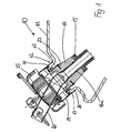
- the tank body 11 has a tank neck 12, which is arranged in a neck extension 26 and has an upper edge 13.
- a separate filler neck 24 is attached to the filler neck 12 a separate filler neck 24 as a carrier of a closure lid 25 in a manner to be described.
- a misfuelling insert 14 is first held in a manner to be described, which holds a ring magnet 15 in its wall.
- a nozzle to be inserted into the filler neck 12 and into the insert 14 extends with the proboscis 16a so deeply into the insert 14 that the annular magnet 15 can apply a closing device (not shown) in the proboscis 16a.
- the insert 14 is attached to a serving as a holder neck piece 17, the neck piece 17 with an upper peripheral flange 18 on the upper edge 13 of the neck extension 26 of the filler neck 12 and projects with a wall 19 inside the tank neck 12.
- 17 screw holes 20 are formed in the flange 18 of the retaining piece through which screws 21 are screwed into the upper edge 13 of the neck extension 26 of the filler neck 12, so that the neck piece 17 fixed to the existing plastic tank body 11th is fixed. Furthermore, in the wall 19 of the neck piece 17 screw holes 22 are arranged through which screws 23 are rotated, which extend into the insert 14 and its wall and thus define the insert 14 on the neck piece 17.
- the attached to the filler neck 12 neck piece 17 is also used for attachment of the filler neck 24 with cover 25 by the neck piece 17 connected to the outer peripheral edge 27 of its upper flange 18 with the outside around the edge 27 inverted filler neck 24, preferably spot welded , Is so that in detail a consisting of neck 17 and filler neck 24 unit is formed, which is placed as a whole on the filler neck 12 until the flange 18 of the neck piece 17 rests on the upper edge 13 of the filler neck 12, so that the described Screwing can be introduced.
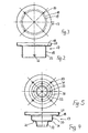
- FIGS. 4 and 5 a modified embodiment of the neck piece 17 is shown, which is designed in two stages.
- an upper cylinder portion 30 with an inner diameter of the filler neck 12 adapted outer diameter wherein the upper cylinder portion 30 merges at its inner end in an inwardly projecting circumferential step 31, to which a second lower cylindrical portion 32 connects, which is adapted in its outer diameter to the inner diameter of the insert such that the insert 14 is slipped over the lower cylinder portion 32 of the neck piece 17, so that the insert 14 in its mounting region on the neck piece 17 on the outside of the lower cylinder portion 32nd to come to rest.
- the provided for the attachment of the insert screw holes 22 are formed in the step 31, so that the correspondingly provided screws 23 are screwed from above into the end face of the insert 14.
- the neck piece 17 has at its upper flange 18 in the FIGS. 2 and 3 described screw holes 20 for screws 21, by means of which the neck piece 17 can be fastened to the tank body 11.
- FIGS. 4 and 5 illustrated embodiment has the advantage that the nozzle 16 with its trunk 16a when inserting at most meets the step 31 of the metallic neck portion 17, so that damage to the insert 14 are excluded with repeated use of the nozzle 16.
- FIGS. 6 and 7 illustrated embodiment shows the formation of the assembly formed from throat 17 and filler neck 24 when mounting this assembly to a metal tank.
- FIGS. 6 and 7 illustrated embodiment first by attaching the patch on the filler neck 12 assembly by the filler neck 24 is connected on its outer circumference with the metal tank 10 and its filler neck 12 by welds 40.
- the structure of the neck piece 17 corresponds in the illustrated embodiment of in FIG. 4 already basically illustrated embodiment with the upper flange portion 18, the upper cylinder portion 30, the inwardly-receding circumferential step 31 and the second lower cylinder portion 32; the attachment of the insert 14 takes place in the FIG. 4 described manner by attaching the corresponding screws 23 in the region of the step 31 such that the screws 23 engage from above into the end face of the insert 14.
- connection of the two partial flanges 18a, 18b can be made for example by a screw 41, either the thread in one or both partial flanges 18a, 18b may be cut, or on the underside of the partial flange 18a an associated nut is permanently attached, in the a guided through the partial flange 18b screw 41th can be screwed.
- Other suitable attachment methods are alternatively conceivable.
- FIGS. 8 and 9 another way of connecting a filler neck to a liquid tank 10 is shown and based on the application of the holder according to the invention, in which the filler neck is integrated into the tank neck 12 and in turn has an internal thread for receiving a screw cap.
- throat piece 17 may be integrally formed as a filler neck by the upper portion of the wall 19 of the neck piece 17 is provided with the internal thread 33.
- the attachment of such a neck formed as a filler neck 17 on the filler neck is basically such that the upper flange 18 of the neck piece 17 is bent around the upper edge 13 of the filler neck and attached thereto. In a tank made of metal, the attachment can be done so that the bent flange 18 welded at its outer edge on the outside with the filler neck 12, preferably spot-welded.
- connection of the throat formed as a filler neck 17 can be carried out already in the manufacture of the plastic tank characterized in that the upper flange of the neck piece 17 surrounds the upper edge 13 of the filler neck 12 in a press fit and is thereby connected thereto.
- FIG. 9 illustrated embodiment shows the in FIG. 4 illustrated embodiment of the neck piece 17 in a simultaneous Training as a filler neck, wherein the upper cylinder portion 30 is used to form the internal thread 33.
- the insert 14 from the tank neck 12 for the purpose of replacement or repair should be removed, according to the in FIG. 10 illustrated embodiment, the stage 31 divided with two overlapping in a sub-area sub-stages 31 a, 31 b executed, the detachable arrangement of the insert on the separate sub-stages 31a, 31b corresponding to the FIGS. 6 and 7 described embodiment is formed.
- the lower part 31 a integral part of the folded flange 18 and from the upper cylinder portion 30 existing portion of the neck piece 17, and as far as this portion is connected via the bent flange 18 fixed to the tank neck of the tank, the lower sub-stage 31st a fixed.
- the insert 14 is in the zu FIGS. 6 and 7 or too FIG.
- a reinforcing ring 35 is shown, as in the case of existing plastic fluid tanks to improve the connection of the neck piece 17 by means of a screw ( Fig. 1 to 5 ) can already be integrated in the preparation of the fluid tank 10 in the neck 26 and the tank neck 12.
- the reinforcing ring 35 consists of a wall portion 37 with a peripheral edge 36 at the flange, and it is integrated in such a way in the manufacture of the plastic tank 10 that the flange 36 forms the upper edge 13 of the filler neck 12, while the wall portion 37, the inner edge region of the filler neck 12th strengthened.
- the reinforcing ring 35 protrude outwardly projecting, bent out of the wall portion 37 tabs 38.
- In the flange 36 are further holes 39 for receiving the fastening screws 21 for the neck piece 17 is formed.
- the insert 14 may be formed in two parts with an outer part 40 which is formed in two stages with a portion 41 of larger diameter and an adjoining portion 42 of smaller diameter, wherein between the sections 41, 42 is an inwardly projecting step 43.
- an inner part 44 is provided, with a larger diameter portion 45 and a smaller diameter portion 46, wherein a step 47 is also formed between the portions 45 and 46.
- Inner part 44 and outer part 40 are matched to one another in such a way that the two parts 40, 44 are inserted into each other with an exact fit.
- the magnet 48 is inserted before the insertion of the inner part 44 in the section 41 of larger diameter of the outer part 40 so that it rests on the step 43 of the outer part 40.
- a second seal 50 is pushed onto the smaller diameter portion 46 of the inner part 44, which is placed in the outer part 40 on the upper side of the magnet 48 during assembly of the inner part 44 and in this respect a seal between the inner part 44 and the outer part 40 causes.
- a flange 51 For mounting the insert 14 to the filler neck 24 ( FIGS. 14 and 15 ) is formed on the upper edge of the outer part 40, a flange 51.
- a protective insert 52 consisting of a high-impact and temperature-resistant plastic is additionally inserted into the upper opening of the insert 14, which has form-locking configurations 53 on its outer circumference which lock with the flange 51 of the outer part 40 so that a simple, but for the purpose of removal of the inner part 44 from the outer part 40 detachable connection between the protective insert 52 and the outer part 40 results.
- the insert 14 is to be used in a tank body made of metal is used on the filler neck 12 of the existing metal tank body 11
- FIG. 14 the filler neck 24 placed on the outside and welded to the tank body 11.
- the filler neck 24 has an inner flange 57, on which the insert 14 is mounted with its outer flange 51, so that a screw connection by means of screws 56 between the insert 14 and the filler neck 24 can be produced.
- the tank body 11 is made of plastic
- a reinforcing ring 57 is inserted into the upper edge of the filler neck 12 already in the production of the tank body, on which the filler neck 24 can be fastened by the filler neck 24 with its inner flange 55 auflagert on the reinforcing ring 57 and can be screwed accordingly.
- a seal 58 is provided between the reinforcing ring 57 and the inner flange 55 of the filler neck 24.
- the insert 14 rests with its outer flange 51 on the inner flange 55 of the Einglall Planns 24, wherein the provided screw on both the outer flange 51 of the insert 14, the inner flange 55 of the filler neck 24 and the reinforcing ring 57 detecting screws 56 be given can.
Landscapes
- Engineering & Computer Science (AREA)
- Life Sciences & Earth Sciences (AREA)
- Sustainable Development (AREA)
- Sustainable Energy (AREA)
- Chemical & Material Sciences (AREA)
- Combustion & Propulsion (AREA)
- Transportation (AREA)
- Mechanical Engineering (AREA)
- Cooling, Air Intake And Gas Exhaust, And Fuel Tank Arrangements In Propulsion Units (AREA)
- Loading And Unloading Of Fuel Tanks Or Ships (AREA)
Claims (26)
- Dispositif destiné à empêcher un mauvais remplissage de réservoir dans des véhicules automobiles, comportant un insert (14), qui est destiné à être monté sur le manchon de réservoir (11), formant un élément du corps de réservoir (10) dans le cas d'un réservoir de fluide dans des véhicules automobiles, et qui est destiné à recevoir un pistolet de distribution de carburant adapté à la configuration de l'insert (14), sachant que dans la paroi de l'insert (14) annulaire, qui est maintenu sur une tubulure de remplissage (24) fixée sur le manchon de réservoir (12) du corps de réservoir (11), est logé un aimant (15, 48) entourant le pistolet de distribution de carburant et coopérant avec un mécanisme de fermeture monté sur le pistolet de distribution de carburant, caractérisé en ce que l'insert (14) est maintenu de manière amovible sur un support, réalisé sous la forme d'un élément à collet (17) avec une paroi (19) à insérer dans le manchon de réservoir (12) et prenant appui sur le manchon de réservoir (12) par un collet (18) périphérique réalisé au niveau de son extrémité supérieure, des orifices (22) étant réalisés dans une zone de l'élément à collet (17) en vue de recevoir des moyens de fixation (23) pour la fixation amovible de l'insert (14) sur l'élément à collet (17), et la zone de l'élément à collet (17), destinée à recevoir les orifices (22), pouvant être désolidarisée du manchon de réservoir (12).
- Dispositif selon la revendication 1, caractérisé en ce que le collet (18) supérieur de l'élément à collet (17) comporte un bord saillant vertical (27) sur son bord périphérique extérieur, et l'élément à collet (17), en vue de former un module à poser sur le manchon de réservoir (12) du corps de réservoir (11), est relié à une tubulure de remplissage (24), enserrant son bord (27) par le dessus et réalisé sous forme de support pour un couvercle de fermeture (25).
- Dispositif selon la revendication 2, caractérisé en ce que, en vue de la fixation du module, formé par l'élément à collet (17) et la tubulure de remplissage (24), sur un réservoir en matière plastique, le collet (18) supérieur de l'élément à collet (17) est posé sur le bord (13) supérieur du manchon de réservoir (12) et est fixé sur le bord (13).
- Dispositif selon la revendication 3, caractérisé en ce que la fixation est formée par un assemblage vissé.
- Dispositif selon la revendication 3 ou 4, caractérisé en ce que l'assemblage vissé est formé par au moins une vis, qui traverse le collet (18) et qui est vissée du côté frontal dans le bord (13) supérieur du manchon de réservoir (12).
- Dispositif selon la revendication 2, caractérisé en ce que , en vue de la fixation du module, formé par l'élément à collet (17) et la tubulure de remplissage (24), sur un réservoir métallique, la tubulure de remplissage (24) est soudée sur le côté extérieur avec le corps de réservoir (11), et le collet (18) de l'élément à collet (17) est réalisé en deux parties avec deux collets partiels (18a, 18b) se chevauchant dans une zone partielle, l'un des collets partiels (18a) étant assemblé par l'intermédiaire du bord (27) de manière fixe avec la tubulure de remplissage (24) et l'autre collet partiel (18b) étant assemblé de manière fixe avec la paroi (19) entourant l'insert (14), et le collet partiel (18b) portant l'insert (14) étant posé sur le collet partiel (18a) et étant assemblé de manière amovible à celui-ci dans la zone de chevauchement et pouvant être retiré hors de la tubulure de remplissage (24).
- Dispositif selon l'une quelconque des revendications 1 à 6, caractérisé en ce que l'élément à collet (17) a une forme cylindrique avec une paroi (19) entourant l'insert (14) au moins partiellement à l'extérieur, et les moyens de fixation (23) traversent la paroi (13) de l'élément à collet (17) et s'engagent dans la paroi de l'insert (14).
- Dispositif selon l'une quelconque des revendications 1 à 6, caractérisé en ce que l'élément à collet (17) a une forme étagée avec une partie cylindrique supérieure (30), ajustée par son diamètre extérieur au diamètre intérieur du manchon de réservoir (12), et une partie cylindrique inférieure (32), qui est aboutée à ladite partie cylindrique supérieure moyennant la formation d'un décrochement (31) en retrait vers l'intérieur et qui a un diamètre extérieur ajusté au diamètre intérieur de l'insert (14), conçu pour recevoir le pistolet de distribution de carburant (16), de telle sorte que l'insert (14) peut être emmanché avec son diamètre intérieur sur la partie cylindrique inférieure (32) de l'élément à collet (17), et les moyens de fixation (23) peuvent être insérés, du côté frontal dans la paroi de l'insert (14), à travers des orifices (22) réalisés dans la zone du décrochement (31).
- Dispositif selon l'une quelconque des revendications 1 à 8, caractérisé en ce que l'élément à collet (17) est réalisé sous la forme d'une tubulure de remplissage intégrale et comporte, dans la zone supérieure de sa paroi (19), un filetage intérieur (33) pour y visser un couvercle de fermeture.
- Dispositif selon les revendications 8 et 9, caractérisé en ce que le filetage intérieur (33) est disposé dans la partie cylindrique supérieure (30) de l'élément à collet (17) réalisé sous la forme d'une tubulure de remplissage.
- Dispositif selon la revendication 9 ou 10, caractérisé en ce que le collet (18) supérieur de l'élément à collet (17), réalisé sous la forme d'une tubulure de remplissage, est cintré de manière à enserrer le bord (13) supérieur du manchon de réservoir (12) et est fixé à celui-ci.
- Dispositif selon la revendication 11, caractérisé en ce que, en présence d'un réservoir métallique, le collet (18) cintré de l'élément à collet (17) est soudé au niveau de son bord extérieur du côté extérieur avec le manchon de réservoir (12) du corps de réservoir (11).
- Dispositif selon la revendication 11, caractérisé en ce que, en présence d'un réservoir réalisé en matière plastique, le collet (18) cintré de l'élément à collet (17) est assemblé par ajustement serré avec le manchon de réservoir (12).
- Dispositif selon l'une quelconque des revendications 9 à 13, caractérisé en ce que l'élément à collet (17) comporte un décrochement (31) pour la fixation de l'insert (14), le décrochement (31) étant réalisé avec deux décrochements partiels (31a, 31b) se chevauchant dans une zone partielle, l'un des décrochements partiels (31a) étant, par l'intermédiaire de la partie cylindrique supérieure (30), une partie intégrale du collet (18) cintré et étant fixé par celle-ci au manchon de réservoir (12), et l'autre décrochement partiel (31b) portant l'insert (14), et le décrochement partiel (31b) étant posé sur le décrochement partiel (31a) et étant assemblé à ce dernier dans la zone de chevauchement et pouvant être retiré hors de l'élément à collet (17) relié de manière fixe au manchon de réservoir.
- Réservoir de liquide (10), réalisé en matière plastique, moyennant l'utilisation d'un dispositif réalisé selon l'une quelconque des revendications 1 à 11 ou 13, dans lequel, lors de la réalisation du réservoir (12) en matière plastique, une bague de raidissement (35), avec un collet (36) périphérique formant le bord (13) supérieur du manchon de réservoir (12) et avec une partie de paroi (37) s'engageant dans le manchon de réservoir (12), est incorporée dans la matière plastique au niveau du manchon de réservoir (12), le support (17) pouvant être fixé sur le manchon de réservoir (12) par le collet (36) de la bague de raidissement (35).
- Réservoir en matière plastique selon la revendication 15, caractérisé en ce que la bague de raidissement (35), sur la face extérieure de sa partie de paroi (37), est munie de pattes (38) qui sont en saillie sur celle-ci et s'engagent dans la matière plastique.
- Dispositif destiné à empêcher un mauvais remplissage de réservoir dans des véhicules automobiles, comportant un insert (14), qui est destiné à être monté sur le manchon de réservoir (11), formant un élément du corps de réservoir (10) dans le cas d'un réservoir de fluide dans des véhicules automobiles, et qui est destiné à recevoir un pistolet de distribution de carburant adapté à la configuration de l'insert (14), sachant que dans la paroi de l'insert (14) annulaire, qui est maintenu sur une tubulure de remplissage (24) fixée sur le manchon de réservoir (12) du corps de réservoir (11), est logé un aimant (15, 48) entourant le pistolet de distribution de carburant et coopérant avec un mécanisme de fermeture monté sur le pistolet de distribution de carburant, caractérisé en ce que l'insert (14), maintenu de manière amovible sur la tubulure de remplissage (24), est formé par deux parties (40, 44) insérables l'une dans l'autre, la partie extérieure (40) et la partie intérieure (44) étant formée chacune par un tronçon cylindrique (41, 45) avec un diamètre plus grand et par un tronçon cylindrique (42, 46) abouté à ce dernier et ayant un plus petit diamètre, et la partie extérieure (40) et la partie intérieure (44) pouvant être enfichées de manière ajustée l'une dans l'autre, et la dimension longitudinale de la partie cylindrique (45) de plus grand diamètre de la partie intérieure (44) étant plus courte que la dimension longitudinale du tronçon (41) associé de la partie extérieure (40) en vue de réaliser un dégagement dans la zone des décrochements (43, 47) formés entre les tronçons de diamètre différent.
- Dispositif selon la revendication 17, caractérisé en ce que l'aimant (48) est disposé dans le dégagement formé entre la partie intérieure (44) et la partie extérieure (40) dans la zone des décrochements (43, 47) de celles-ci.
- Dispositif selon la revendication 17 ou 18, caractérisé en ce que sur le décrochement (43) formé dans la partie extérieure (40) est posée une garniture d'étanchéité (49), qui assure l'étanchéité de l'intervalle formé, lorsque la partie intérieure (44) est enfichée dans la partie extérieure (40), entre les tronçons (42, 46) enfichés l'un dans l'autre avec un diamètre plus petit, et sur laquelle est posé l'aimant (48), et en ce que, au-dessus de l'aimant (48), une garniture d'étanchéité (50) supplémentaire est enfichée sur le tronçon (46) de plus petit diamètre de la partie intérieure (44).
- Dispositif selon l'une quelconque des revendications 17 à 19, caractérisé en ce que l'insert (14) est posé avec un collet (51), formé sur le bord supérieur de sa partie extérieure (40), sur un collet intérieur (55), réalisé sur le côté intérieur de la tubulure de remplissage (24), et est assemblé à la tubulure de remplissage (24).
- Dispositif selon l'une quelconque des revendications 17 à 20, caractérisé en ce que dans l'orifice de réception de l'insert (14), formé conjointement dans la partie extérieure (40) et la partie intérieure (44), est inséré un élément de protection (52) réalisé en matière plastique résistant aux chocs élevés et résistant à la température, lequel est destiné à recevoir le pistolet de distribution de carburant et guide le pistolet de distribution de carburant au moment de son introduction.
- Dispositif selon la revendication 21, caractérisé en ce que l'élément de protection (52) est assemblé par conjugaison de forme avec le collet (51) réalisé sur la partie extérieure (40) de l'insert (14) et, de ce fait, est fixé sur l'insert (14).
- Dispositif selon l'une quelconque des revendications 17 à 22, caractérisé en ce que, en présence d'un corps de réservoir (11) réalisé en métal, la tubulure de remplissage (24) enserre le manchon de réservoir (12) par le dessus et est soudé du côté extérieur avec le corps de réservoir (11).
- Dispositif selon l'une quelconque des revendications 17 à 22, caractérisé en ce que, en présence d'un corps de réservoir (11) réalisé en matière plastique, une bague de raidissement (57) est incorporée dans le bord supérieur du manchon de réservoir (12), et la tubulure de remplissage (24), posée sur le manchon de réservoir (12) peut être reliée à la bague de raidissement (57) par des assemblages vissés (56).
- Dispositif selon la revendication 24, caractérisé en ce que la tubulure de remplissage (24), avec le collet intérieur (55) formé sur celle-ci, est posée sur la bague de raidissement (57) du manchon de réservoir (12), et les assemblages vissés (56), y compris l'insert (14), sont destinés à la fixation de la tubulure de remplissage (24) sur le manchon de réservoir (12).
- Dispositif selon la revendication 24 ou 25, caractérisé en ce qu'une garniture d'étanchéité (58) supplémentaire est posée entre le manchon de réservoir (12) et la tubulure de remplissage (24).
Applications Claiming Priority (4)
| Application Number | Priority Date | Filing Date | Title |
|---|---|---|---|
| DE20312178U | 2003-08-01 | ||
| DE20312178U DE20312178U1 (de) | 2003-08-01 | 2003-08-01 | Fehlbetankungseinsatz-Halterung für Flüssigkeitstanks an Kraftfahrzeugen |
| DE20315807U | 2003-10-10 | ||
| DE20315807U DE20315807U1 (de) | 2003-10-10 | 2003-10-10 | Fehlbetankungseinsatz-Halterung für Fluidtanks an Kraftfahrzeugen |
Publications (3)
| Publication Number | Publication Date |
|---|---|
| EP1502794A2 EP1502794A2 (fr) | 2005-02-02 |
| EP1502794A3 EP1502794A3 (fr) | 2006-05-17 |
| EP1502794B1 true EP1502794B1 (fr) | 2008-11-12 |
Family
ID=33542409
Family Applications (1)
| Application Number | Title | Priority Date | Filing Date |
|---|---|---|---|
| EP20040017171 Expired - Lifetime EP1502794B1 (fr) | 2003-08-01 | 2004-07-21 | Dispositif pour éviter un mauvais remplissage de carburant dans des automobiles |
Country Status (2)
| Country | Link |
|---|---|
| EP (1) | EP1502794B1 (fr) |
| DE (1) | DE502004008441D1 (fr) |
Families Citing this family (13)
| Publication number | Priority date | Publication date | Assignee | Title |
|---|---|---|---|---|
| DE202005011575U1 (de) | 2005-07-13 | 2006-11-23 | Reutter Metallwarenfabrik Gmbh | Einfüllstutzen für einen Behälter |
| DE102008049150A1 (de) * | 2008-06-09 | 2009-12-10 | Kt Projektentwicklungs-Gmbh | Einsatzelement für einen zur tankstellenseitigen Befüllung mit Harnstoff geeigneten Behälter |
| DE202009001182U1 (de) | 2009-01-30 | 2009-04-30 | Jost Automotive Gmbh | Vorrichtung zur Verhinderung einer Fehlbetankung |
| DE102009029362A1 (de) | 2009-09-11 | 2011-03-24 | Erhard & Söhne GmbH | Behaelter zur Aufnahme eines Kraft- und/oder Betriebsstoffes fuer Fahrzeuge |
| EP2316685A1 (fr) * | 2009-10-21 | 2011-05-04 | Inergy Automotive Systems Research (Société Anonyme) | Système de remplissage amélioré pour conteneur fluide véhiculaire |
| DE202010016319U1 (de) * | 2010-12-04 | 2012-03-19 | Reutter Gmbh | Einsatz für einen Einfüllstutzen eines Harnstoffbehälters |
| DE202011100846U1 (de) * | 2011-05-16 | 2012-08-17 | Reutter Gmbh | Einfüllstutzen für einen Harnstoffbehälter und einen damit versehenen Harnstoffbehälter |
| DE102011120787A1 (de) * | 2011-06-29 | 2013-01-03 | Volkswagen Aktiengesellschaft | Fehlbetankungsschutzvorrichtung für einen Einfüllstutzen eines Kraftstoffbehälters |
| DE102011113101A1 (de) | 2011-09-09 | 2013-03-14 | Volkswagen Aktiengesellschaft | Einfüllstutzen für ein Fahrzeug |
| KR101500136B1 (ko) * | 2013-09-06 | 2015-03-06 | 현대자동차주식회사 | 차량의 오주유 방지장치 |
| FR3020355B1 (fr) * | 2014-04-29 | 2017-05-26 | Illinois Tool Works | Dispositif de remplissage, ensemble de remplissage, reservoir de liquide, vehicule automobile et procede de mise en oeuvre |
| CN114673583B (zh) * | 2020-12-24 | 2023-05-12 | 长城汽车股份有限公司 | 车辆加注控制方法、装置、存储介质、控制器及车辆 |
| US12085216B2 (en) | 2022-02-17 | 2024-09-10 | Arctic Cat Inc. | Multi-use fuel filler tube |
Family Cites Families (4)
| Publication number | Priority date | Publication date | Assignee | Title |
|---|---|---|---|---|
| DE3425461A1 (de) * | 1984-07-11 | 1986-01-23 | Robert Bosch Gmbh, 7000 Stuttgart | Schutzeinrichtung fuer kraftfahrzeuge |
| US5562133A (en) * | 1994-06-24 | 1996-10-08 | Hiesky Corporation | Fuel dispensing nozzle |
| US5474115A (en) * | 1994-08-04 | 1995-12-12 | Husky Corporation | Specialty fuel dispensing nozzle |
| DE10037824B4 (de) * | 2000-08-03 | 2009-06-10 | Daimler Ag | Vorrichtung zum Verhindern des Einführens einer Zapfpistole |
-
2004
- 2004-07-21 DE DE200450008441 patent/DE502004008441D1/de not_active Expired - Fee Related
- 2004-07-21 EP EP20040017171 patent/EP1502794B1/fr not_active Expired - Lifetime
Also Published As
| Publication number | Publication date |
|---|---|
| EP1502794A3 (fr) | 2006-05-17 |
| EP1502794A2 (fr) | 2005-02-02 |
| DE502004008441D1 (de) | 2008-12-24 |
Similar Documents
| Publication | Publication Date | Title |
|---|---|---|
| EP1502794B1 (fr) | Dispositif pour éviter un mauvais remplissage de carburant dans des automobiles | |
| EP0696994B1 (fr) | Capuchon pour bouteille | |
| EP2102484B1 (fr) | Filtre à carburant d'un moteur à combustion de véhicule | |
| DE4318279C2 (de) | Airbaganordnung | |
| EP2340956B1 (fr) | Tubulures de remplissage pour un réservoir de liquide, notamment un réservoir d'urée sur des véhicules automobiles | |
| DE102008049150A1 (de) | Einsatzelement für einen zur tankstellenseitigen Befüllung mit Harnstoff geeigneten Behälter | |
| EP3793712B1 (fr) | Élément filtrant, système de filtration équipé d'un élément filtrant et procédé | |
| EP0756338A1 (fr) | Montage de bouchon pour fermer d'ouvertures individuelles de cellules d'accumulateur | |
| EP0810164A1 (fr) | Appareil pour la préparation d'un mélange d'un ingrédient actif et d'un diluant et procédé pour remplir une cartouche utilisée dans un tel appareil | |
| DE602006000557T2 (de) | Strukturkörper für Kraftstoffpumpenbefestigung | |
| DE69103620T2 (de) | Flüssigkeitsbehälter mit abnehmbarer Verkleidung. | |
| DE29511368U1 (de) | Getränkedosenverschluß | |
| EP2665901A1 (fr) | Tubulure de remplissage pour un réservoir de liquide, en particulier un réservoir d'urée, sur des véhicules automobiles | |
| DE19714942A1 (de) | Trichter für einen Behälter für gefährlichen Abfall | |
| DE19957253A1 (de) | Kraftstoffbehälter | |
| EP1077824B1 (fr) | Reservoir de carburant | |
| EP0943477B1 (fr) | Fermeture pour réservoir de carburant | |
| DE102013222908A1 (de) | Hydrauliktank | |
| DE20315807U1 (de) | Fehlbetankungseinsatz-Halterung für Fluidtanks an Kraftfahrzeugen | |
| WO2018050237A1 (fr) | Dispositif filtrant, notamment filtre à air, pour un système d'air frais d'un moteur à combustion interne | |
| DE2559110A1 (de) | Katalysatorbehaelter fuer eine abgassammelleitung | |
| DE102019218686A1 (de) | Öffnungsvorrichtung für den harnstoffwassereinlass einesfahrzeugs | |
| EP0799738B1 (fr) | Réservoir de carburant en matière plastique | |
| DE19602819A1 (de) | Kraftstoffbehälter | |
| DE3714890A1 (de) | Behaelter mit nicht abnehmbarem deckel |
Legal Events
| Date | Code | Title | Description |
|---|---|---|---|
| PUAI | Public reference made under article 153(3) epc to a published international application that has entered the european phase |
Free format text: ORIGINAL CODE: 0009012 |
|
| AK | Designated contracting states |
Kind code of ref document: A2 Designated state(s): AT BE BG CH CY CZ DE DK EE ES FI FR GB GR HU IE IT LI LU MC NL PL PT RO SE SI SK TR |
|
| AX | Request for extension of the european patent |
Extension state: AL HR LT LV MK |
|
| PUAL | Search report despatched |
Free format text: ORIGINAL CODE: 0009013 |
|
| AK | Designated contracting states |
Kind code of ref document: A3 Designated state(s): AT BE BG CH CY CZ DE DK EE ES FI FR GB GR HU IE IT LI LU MC NL PL PT RO SE SI SK TR |
|
| AX | Request for extension of the european patent |
Extension state: AL HR LT LV MK |
|
| 17P | Request for examination filed |
Effective date: 20061026 |
|
| 17Q | First examination report despatched |
Effective date: 20061207 |
|
| AKX | Designation fees paid |
Designated state(s): DE ES IT |
|
| GRAP | Despatch of communication of intention to grant a patent |
Free format text: ORIGINAL CODE: EPIDOSNIGR1 |
|
| RAP1 | Party data changed (applicant data changed or rights of an application transferred) |
Owner name: JOST AUTOMOTIVE GMBH |
|
| RIN1 | Information on inventor provided before grant (corrected) |
Inventor name: JOST, INGO |
|
| GRAS | Grant fee paid |
Free format text: ORIGINAL CODE: EPIDOSNIGR3 |
|
| GRAA | (expected) grant |
Free format text: ORIGINAL CODE: 0009210 |
|
| AK | Designated contracting states |
Kind code of ref document: B1 Designated state(s): DE ES IT |
|
| REF | Corresponds to: |
Ref document number: 502004008441 Country of ref document: DE Date of ref document: 20081224 Kind code of ref document: P |
|
| PG25 | Lapsed in a contracting state [announced via postgrant information from national office to epo] |
Ref country code: ES Free format text: LAPSE BECAUSE OF FAILURE TO SUBMIT A TRANSLATION OF THE DESCRIPTION OR TO PAY THE FEE WITHIN THE PRESCRIBED TIME-LIMIT Effective date: 20090223 |
|
| PLBE | No opposition filed within time limit |
Free format text: ORIGINAL CODE: 0009261 |
|
| STAA | Information on the status of an ep patent application or granted ep patent |
Free format text: STATUS: NO OPPOSITION FILED WITHIN TIME LIMIT |
|
| 26N | No opposition filed |
Effective date: 20090813 |
|
| PG25 | Lapsed in a contracting state [announced via postgrant information from national office to epo] |
Ref country code: DE Free format text: LAPSE BECAUSE OF NON-PAYMENT OF DUE FEES Effective date: 20100202 |
|
| PG25 | Lapsed in a contracting state [announced via postgrant information from national office to epo] |
Ref country code: IT Free format text: LAPSE BECAUSE OF FAILURE TO SUBMIT A TRANSLATION OF THE DESCRIPTION OR TO PAY THE FEE WITHIN THE PRESCRIBED TIME-LIMIT Effective date: 20081112 |