EP1502810B1 - Agencement de sièges de véhicules - Google Patents
Agencement de sièges de véhicules Download PDFInfo
- Publication number
- EP1502810B1 EP1502810B1 EP04017715A EP04017715A EP1502810B1 EP 1502810 B1 EP1502810 B1 EP 1502810B1 EP 04017715 A EP04017715 A EP 04017715A EP 04017715 A EP04017715 A EP 04017715A EP 1502810 B1 EP1502810 B1 EP 1502810B1
- Authority
- EP
- European Patent Office
- Prior art keywords
- seat
- arrangement according
- headrest
- support element
- backrest
- Prior art date
- Legal status (The legal status is an assumption and is not a legal conclusion. Google has not performed a legal analysis and makes no representation as to the accuracy of the status listed.)
- Expired - Lifetime
Links
- 239000002184 metal Substances 0.000 claims abstract 2
- 238000009434 installation Methods 0.000 claims description 10
- 230000013011 mating Effects 0.000 claims description 6
- 230000005540 biological transmission Effects 0.000 claims description 5
- 238000010276 construction Methods 0.000 claims description 2
- 230000000007 visual effect Effects 0.000 claims 1
- 230000006378 damage Effects 0.000 description 2
- 208000027418 Wounds and injury Diseases 0.000 description 1
- 230000006978 adaptation Effects 0.000 description 1
- 230000000712 assembly Effects 0.000 description 1
- 238000000429 assembly Methods 0.000 description 1
- 230000015572 biosynthetic process Effects 0.000 description 1
- 238000006073 displacement reaction Methods 0.000 description 1
- 239000004744 fabric Substances 0.000 description 1
- 208000014674 injury Diseases 0.000 description 1
- 230000003993 interaction Effects 0.000 description 1
- 239000010985 leather Substances 0.000 description 1
- 239000000463 material Substances 0.000 description 1
- 230000001681 protective effect Effects 0.000 description 1
- 239000000725 suspension Substances 0.000 description 1
Images


Classifications
-
- B—PERFORMING OPERATIONS; TRANSPORTING
- B60—VEHICLES IN GENERAL
- B60N—SEATS SPECIALLY ADAPTED FOR VEHICLES; VEHICLE PASSENGER ACCOMMODATION NOT OTHERWISE PROVIDED FOR
- B60N2/00—Seats specially adapted for vehicles; Arrangement or mounting of seats in vehicles
- B60N2/68—Seat frames
- B60N2/686—Panel like structures
-
- B—PERFORMING OPERATIONS; TRANSPORTING
- B60—VEHICLES IN GENERAL
- B60N—SEATS SPECIALLY ADAPTED FOR VEHICLES; VEHICLE PASSENGER ACCOMMODATION NOT OTHERWISE PROVIDED FOR
- B60N2/00—Seats specially adapted for vehicles; Arrangement or mounting of seats in vehicles
- B60N2/70—Upholstery springs ; Upholstery
- B60N2/7005—Upholstery springs ; Upholstery detachable
-
- B—PERFORMING OPERATIONS; TRANSPORTING
- B60—VEHICLES IN GENERAL
- B60N—SEATS SPECIALLY ADAPTED FOR VEHICLES; VEHICLE PASSENGER ACCOMMODATION NOT OTHERWISE PROVIDED FOR
- B60N2/00—Seats specially adapted for vehicles; Arrangement or mounting of seats in vehicles
- B60N2/80—Head-rests
- B60N2/806—Head-rests movable or adjustable
- B60N2/809—Head-rests movable or adjustable vertically slidable
- B60N2/829—Head-rests movable or adjustable vertically slidable characterised by their adjusting mechanisms, e.g. electric motors
-
- B—PERFORMING OPERATIONS; TRANSPORTING
- B60—VEHICLES IN GENERAL
- B60N—SEATS SPECIALLY ADAPTED FOR VEHICLES; VEHICLE PASSENGER ACCOMMODATION NOT OTHERWISE PROVIDED FOR
- B60N2/00—Seats specially adapted for vehicles; Arrangement or mounting of seats in vehicles
- B60N2/80—Head-rests
- B60N2/882—Head-rests detachable
-
- B—PERFORMING OPERATIONS; TRANSPORTING
- B60—VEHICLES IN GENERAL
- B60N—SEATS SPECIALLY ADAPTED FOR VEHICLES; VEHICLE PASSENGER ACCOMMODATION NOT OTHERWISE PROVIDED FOR
- B60N3/00—Arrangements or adaptations of other passenger fittings, not otherwise provided for
- B60N3/10—Arrangements or adaptations of other passenger fittings, not otherwise provided for of receptacles for food or beverages, e.g. refrigerated
- B60N3/102—Arrangements or adaptations of other passenger fittings, not otherwise provided for of receptacles for food or beverages, e.g. refrigerated storable or foldable in a non-use position
-
- B—PERFORMING OPERATIONS; TRANSPORTING
- B60—VEHICLES IN GENERAL
- B60R—VEHICLES, VEHICLE FITTINGS, OR VEHICLE PARTS, NOT OTHERWISE PROVIDED FOR
- B60R11/00—Arrangements for holding or mounting articles, not otherwise provided for
-
- B—PERFORMING OPERATIONS; TRANSPORTING
- B60—VEHICLES IN GENERAL
- B60R—VEHICLES, VEHICLE FITTINGS, OR VEHICLE PARTS, NOT OTHERWISE PROVIDED FOR
- B60R11/00—Arrangements for holding or mounting articles, not otherwise provided for
- B60R11/02—Arrangements for holding or mounting articles, not otherwise provided for for radio sets, television sets, telephones, or the like; Arrangement of controls thereof
-
- B—PERFORMING OPERATIONS; TRANSPORTING
- B60—VEHICLES IN GENERAL
- B60R—VEHICLES, VEHICLE FITTINGS, OR VEHICLE PARTS, NOT OTHERWISE PROVIDED FOR
- B60R11/00—Arrangements for holding or mounting articles, not otherwise provided for
- B60R11/02—Arrangements for holding or mounting articles, not otherwise provided for for radio sets, television sets, telephones, or the like; Arrangement of controls thereof
- B60R11/0229—Arrangements for holding or mounting articles, not otherwise provided for for radio sets, television sets, telephones, or the like; Arrangement of controls thereof for displays, e.g. cathodic tubes
- B60R11/0235—Arrangements for holding or mounting articles, not otherwise provided for for radio sets, television sets, telephones, or the like; Arrangement of controls thereof for displays, e.g. cathodic tubes of flat type, e.g. LCD
-
- B—PERFORMING OPERATIONS; TRANSPORTING
- B60—VEHICLES IN GENERAL
- B60R—VEHICLES, VEHICLE FITTINGS, OR VEHICLE PARTS, NOT OTHERWISE PROVIDED FOR
- B60R13/00—Elements for body-finishing, identifying, or decorating; Arrangements or adaptations for advertising purposes
- B60R13/02—Internal Trim mouldings ; Internal Ledges; Wall liners for passenger compartments; Roof liners
-
- B—PERFORMING OPERATIONS; TRANSPORTING
- B60—VEHICLES IN GENERAL
- B60R—VEHICLES, VEHICLE FITTINGS, OR VEHICLE PARTS, NOT OTHERWISE PROVIDED FOR
- B60R11/00—Arrangements for holding or mounting articles, not otherwise provided for
- B60R2011/0001—Arrangements for holding or mounting articles, not otherwise provided for characterised by position
- B60R2011/0003—Arrangements for holding or mounting articles, not otherwise provided for characterised by position inside the vehicle
- B60R2011/0012—Seats or parts thereof
- B60R2011/0015—Back-rests
-
- B—PERFORMING OPERATIONS; TRANSPORTING
- B60—VEHICLES IN GENERAL
- B60R—VEHICLES, VEHICLE FITTINGS, OR VEHICLE PARTS, NOT OTHERWISE PROVIDED FOR
- B60R11/00—Arrangements for holding or mounting articles, not otherwise provided for
- B60R2011/0042—Arrangements for holding or mounting articles, not otherwise provided for characterised by mounting means
- B60R2011/0049—Arrangements for holding or mounting articles, not otherwise provided for characterised by mounting means for non integrated articles
- B60R2011/005—Connection with the vehicle part
-
- B—PERFORMING OPERATIONS; TRANSPORTING
- B60—VEHICLES IN GENERAL
- B60R—VEHICLES, VEHICLE FITTINGS, OR VEHICLE PARTS, NOT OTHERWISE PROVIDED FOR
- B60R11/00—Arrangements for holding or mounting articles, not otherwise provided for
- B60R2011/0042—Arrangements for holding or mounting articles, not otherwise provided for characterised by mounting means
- B60R2011/0049—Arrangements for holding or mounting articles, not otherwise provided for characterised by mounting means for non integrated articles
- B60R2011/005—Connection with the vehicle part
- B60R2011/0059—Connection with the vehicle part using clips, clamps, straps or the like
Definitions
- the invention relates to a seat arrangement for vehicles according to claim 1.
- the two front vehicle seats of a passenger limousine are typically formed as a single seat in each case by a seat back support structure provided with a padding in the form of a backrest frame.
- the back frame is designed in the manner of an upside-down U and typically has two substantially vertically oriented, spaced apart in the vehicle transverse direction spars, which are connected to each other at its upper, free end by a cross-beam.
- the two spars are pivotable about an axis extending in the vehicle transverse direction, arranged at the lower end of the spars axis and lockable in several pivotal positions.
- the back frame is also conventionally provided with a plurality of spring elements that provide the necessary to achieve the desired seating comfort elasticity.
- the headrest To attach the headrest to the backrest of the front seat, the headrest usually has two support rods, which are held in a reclining frame side receiving device.
- a guide is provided in the upper cross-beam of the back frame, such that the two support rods push through the upper cross-beam of the backrest frame substantially vertically.
- headrests are made by companies other than the seat backs of the vehicle seat, so in terms of the constructive connection of the headrest to a seat back and in terms of their assembly a variety of agreements between the headrest manufacturer and the seat manufacturer needs.
- a problem in this context is that the installation space available for the installation of the receiving device for the headrest on the back frame is very small.
- An optimal adaptation of the headrest to the backrest, in particular with regard to their rattle in use and in terms of an accurate dimensional stability for proper adjustment is achievable only to a limited extent.
- the two support rods of the headrest are often arranged closely adjacent each other. Even if the two support rods are attached to the outer edge regions of the headrest, the attachment points of the support rods are located on the cross-beam relatively close to the center of the cross-beam.
- the crossbeam of the back frame is often designed to be very thin, so that it can come in a crash, in which can be exercised on the headrest very large forces, to a twisting of the crossbeam and an associated risk of injury.
- From the DE 100 29 624 A1 is a seating arrangement in which a usable for different purposes storage compartment can be located either in the backrest or in the headrest of the front vehicle seat.
- An adjustable headrest is arranged on the backrest part, wherein it can be assumed that the support bars of the headrest are held by a receiving device which is arranged on a crosspiece of the backrest frame of the backrest, as is typically the case.
- the object of the invention is to develop the seat assembly such that with a simple design, an improved attachment of the headrest on the back frame and the functional unit on the backrest is possible.
- the principle of the invention thus consists essentially in the headrest and a mounting panel for the functional unit to a to summarize common structural unit, which is attached to the entire backrest frame.
- the structural unit designed as a supporting element furthermore comprises a power-line component which directly introduces the forces exerted on the headrest in the event of a crash into the frame structure of the backrest frame.
- the power line component can be designed to be highly torsion-resistant, and therefore, for example, have a cross section that is significantly larger than the cross section of conventional transverse members of backrest frames or a more stable construction.
- the support element bridges the distance between the two beams substantially.
- the structural element, the headrest and the functional unit can be structurally modified, e.g. be optimally adapted to each other in terms of force transmission, since the entire unit is attached to the back frame. It thus eliminates a complex assembly of items on site, with the possibility of dimensioning the receiving device almost arbitrarily.
- the in the prior art only extremely small installation space for the receiving device, which was limited by the dimensions of the cross-beam, is now significantly increased.
- the receiving device for the headrest according to the invention is attached to the separate support element, an advantageous assembly pre-assembly can be carried out with better accessibility of a mounting base for the receiving device.
- the solution according to the invention also offers the possibility of a better force introduction of the forces exerted on the headrest in the event of a crash forces in the frame structure of the back frame, since the support element can be attached directly to the two bars of the back frame or at least in the immediate vicinity of the spars, so that an immediate Force transmission is possible.
- the support element or of a arranged on the support member power line component and large forces can be forwarded.
- the seat assembly according to the invention also allows easy replacement of the functional unit, the headrest and the support element, so that can be spoken of a modular design.
- a modular design also facilitates interchangeability of a mounted support element, for example, in the event that a user desires another functional unit or if essential components must be replaced in the event of damage.
- the support member may be provided for this purpose with particularly simple designed fasteners, as well as Having connection elements for supply lines, which can be connected to the back-side mating connection elements.
- a seating arrangement in which at the rear of the back of a double seat, a screen and a fold-out table top is arranged.
- the screen is arranged for example in the headrest and the table top in the backrest, the headrest with the backrest forms a one-piece component.
- non-generic DE 43 25 996 C2 is a non-generic seat arrangement shown, in which the headrest is arranged by means of two support rods in guide sleeves of the upper cross member of a substantially U-shaped back frame.
- a device for height adjustment is connected via fastening hooks with the frame of the backrest body.
- From the DE-PS 19 45 571 is a non-generic seat arrangement, in which for securing the headrest to the backrest of a vehicle seat, a clasp-like web arrangement is provided which engages over the backrest of her backrest head.
- a non-generic seating arrangement in which for attachment of the headrest on the back frame a substantially U-shaped yoke is provided, which is fastened laterally by means of fastening screws to the bars of the back frame.
- From the DE-OS 16 80 264 is also a non-generic seat arrangement, in which the headrest is subsequently mounted by means of a web arrangement on an existing backrest.
- the support element extends substantially over the entire width and / or substantially over the entire height of the back of the backrest.
- a significant advantage is that the support element can form substantially the rear wall of the backrest.
- the support element is fastened to an already upholstered seat back support structure from the rear thereof, wherein this attachment step is the last assembly step of the backrest.
- the wording according to which the support element extends substantially over the entire width or substantially over the entire height of the rear side of the backrest should also include embodiments in which only a substantial part of the rear side of the backrest is covered by the support element ,
- the invention also leaves open the possibility that the support element is laminated on its side facing the rear vehicle seat, for example, with a fabric or covered with leather or possibly also has a padding.
- the invention also includes such support elements that form at least a portion of the backrest head.
- the support element such that it forms the back of the backrest in the manner of a closure shell.
- the rear vehicle seat facing the rear wall of the backrest is substantially formed by the support member.
- the headrest is releasably supported by means of at least one support rod in the receiving device.
- the headrest is held in the receiving device by means of two support rods spaced apart in the vehicle transverse direction.
- the easy solubility of the headrest, in particular such that the support rods from the receiving device are completely removable, is of particular importance, for example, to attach a protective cover to the headrest or to solve the headrest for other reasons in a simple manner if necessary.
- a co-operating with the headrest control is arranged on the support element.
- a control for example, a device for electrical height adjustment, a device for crash-active headrest control or to trigger headrest airbags, etc. be.
- the support element offers therefore, the possibility to arrange such controls directly to the existing support element, receiving device and mounting panel assembly, so that a further improved assembly, for example, due to improved accessibility is possible.
- the support member for attaching to the seat back support structure from the back of the seat back support structure forth on this can be attached, in particular attachable to this.
- This embodiment of the invention enables a particularly simple mounting of the support element on the seat back support structure such that this attachment step represents the last assembly step for the completion of the seat assembly.
- the support member to the back frame by means of fastening elements can be fastened, which cooperate with reclining frame side, arranged in the immediate vicinity of the spars or on the spars counter-fastening elements.
- fastening elements and counter-fastening elements By arranging fastening elements and counter-fastening elements, a particularly simple locking of the support element to the backrest frame can take place.
- plug-in connections, snap-in connections or comparable connections which lock the support element to the backrest frame, which connections allow secure fastening of the support element to the seat back support structure.
- fasteners a particularly simple mounting of the support element to the seat back support structure.
- the support element is formed substantially plate-shaped. Such a configuration favors the formation of a rear wall of the seat back by the support element.
- the support element has connection elements for supply lines, e.g. Power supply lines, signal or data lines, pneumatic or vacuum lines connected to lean-side mating connection elements, e.g. can be brought into plug connection.
- connection elements for supply lines e.g. Power supply lines, signal or data lines, pneumatic or vacuum lines connected to lean-side mating connection elements, e.g. can be brought into plug connection.
- predefined connection points can be provided, which can connect the functional unit or, for example, a headrest cooperating control with the necessary operating voltage or with a required signal line or a vacuum line.
- the seat assembly according to the invention is designated in its entirety by 10.
- Fig. 1 shows a motor vehicle 11 with an inventive, consisting of two individual seats 12, 13 seat assembly 10, the sake of clarity, the rear seat has been omitted.
- the viewer of Fig. 1 However, a rear seat 14 behind the two individual seats 12, 13 imagine, as for example the embodiment of Fig. 5 shows.
- Each individual seat 12, 13 has a seat surface part 15 and a backrest 16.
- the backrest 16 is formed by a seat back support structure 17, which is typically formed as a back frame 18, which has substantially the shape of an upside-down U.
- the back frame 18 is made in particular Fig. 3 can be seen and has two substantially vertically aligned, side rails 19a, 19b and a cross-beam 20, which connects the two upper ends of the spars together.
- the spars 19a, 19b are pivotable about a pivot axis 32 located in the lower connection region of the bar ends, which extends essentially transversely to the direction of travel X, and enable pivoting the backrest 16, which is lockable in different pivotal positions.
- spring elements that provide a certain elasticity of the backrest and upholstery, which in the Figures 1 and 2 however, are indicated.
- the cross-beam 20 is provided in its central region with corresponding receptacles and guides.
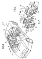
- a support member 24 is provided, which is formed separately from the back frame 18 and which, as best the FIGS. 3 and 4 make clear, a receiving device 23 for the support rods 22a, 22b of the headrest 21 and a mounting panel 26 for a functional unit 27 has.
- the receiving device 23 may be arranged for example on a power line component 25, which is formed for example as a cross member.
- the installation field 26 is arranged on the rear seat 33, which is the rear seat backrest 33, of the backrest 16, that is, the rear seat backrest 14.
- the support member 24 is formed in the embodiment according to all figures substantially plate-shaped and has a width B which corresponds substantially to the width BR of the backrest 16.
- the support member 24 also has a height H, which corresponds substantially to the height HR of the backrest 16.
- the height H of the support element 24 substantially corresponds to the length L of the spars 19a, 19b.
- fastening means 28 are provided, which are arranged on the support member side and counter-fastening means 29 which are arranged on the reclining frame side.
- the Figures 2 and 4 let recognize that the fastening means 28 and counter-fastening means 29 can be connected to each other along mounting directions by mutually aligned arrangement, so that the support element 24 can be attached to the backrest 16 from the back 34 of the back frame 18.
- the backrest 16 already largely prefabricate, such that the back frame 18 is provided with a Umpolsterung and the last assembly step, the attachment of the support member 24 is made on the back frame 18.
- connection elements may be provided on the support member 24, which allow a connection with supply lines, wherein the support element-side connection elements with backrest side, in particular reclining frame side mating connection elements can be brought into connection. If it should be necessary for a functional unit, such as a screen, to be supplied with power, the installation panel for the functional unit can already have corresponding connections, in particular plug connections, so that the functional unit only has to be plugged in.
- the connections in the installation field 26 of the support element 24 are supplied with the required operating voltage via a contact-element-side connection element, which is connected to a back-side mating connection element during assembly of the support element 24 to the back frame 18 with this.
- FIGS. 3 and 4 as well as the right single seat 13 in the Figures 1 and 2 show a pivotable about a pivot axis 31 tray 30, which has, for example, a cup or cup holder.
- the in each left individual seat 12 of Figures 1 and 2 indicated screen 35 represents another possible, a functional unit 27 forming component.
- the storage compartment 36 of each left individual seat 12 of Figures 1 and 2 is a functional unit within the meaning of the invention.
- the corresponding installation field 26 for the screen 35 or for the storage compartment 36 is within the meaning of the present patent application each located immediately behind the functional component 27, 35, 36 mounting surface of the support member 24.
- the installation panel 26 but equally a storage compartment or a fastening device for a Training functional unit.
- FIG. 5 also shows mirror elements, such as make-up mirrors, nets, the pocket-like recordings for storing magazines od. Like. form, are possible as shelves 37 and cup holder 38 trained functional units , In any case, the functional units 27 are those devices which offer a certain functionality for a user located in the rear seat.
- the cross-member 25 formed as a force component of the support member 24 may be formed much more stable than the cross-beam 20 of the back frame 18.
- the forces collected by the headrest 21 in the event of a crash are directly on the support rods 22a, 22b and the power line component 25 in introduced the spars 19a, 19b, so that a twist in the event of a crash can be avoided.
- the fastening elements 28 therefore serve for direct attachment to counter-fastening elements 29, which are arranged directly on the bars 19a, 19b or at least in the immediate vicinity of the spars. In this way, a force introduction of the forces occurring in the event of a crash can be done in a short way.
- the support member 24 may also function as a dazzle-like component which cover attachment areas of the padding, such as attachment areas 39 of the padding in the region of the backrest head 40 or mounting portions 41 of the padding in the region of the side cheeks of the backrest 16 such that the attachment of the padding on the back frame is simplified.
- the support element 24 can thus cover, as an optically terminating element, unsightly attachment areas 39, 41, thereby allowing a simplified attachment of the upholstery.
- the number of fasteners and mating fasteners 28, 29 is limited to four in the embodiment in the figures. In principle, however, a larger number of fasteners is possible, the point-like but equally may be formed like a strip.
- the backrest head 40 of the backrest 16 can be made significantly more stable, but it can also be an increase in the torsional stiffness of the backrest 16 can be achieved overall.
- the power line component 25 may also extend over the entire height H of the support element 24. In the event that the support element 24 is designed to be stable, it may be possible to dispense with the transverse members 20 of the back frame 18 required in the prior art.
- the support member may for example consist of plastic, wherein different components of the support element 24 may also consist of different materials. It is also advantageous that the support element 24 can form regions of the rear wall of the backrest 16, which provide an immediate outer end surface of the backrest 16. Alternatively, it is of course also possible that the support member 24 is provided on its back 33 with a padding.
Landscapes
- Engineering & Computer Science (AREA)
- Mechanical Engineering (AREA)
- Transportation (AREA)
- Aviation & Aerospace Engineering (AREA)
- Physics & Mathematics (AREA)
- Thermal Sciences (AREA)
- Seats For Vehicles (AREA)
- Chair Legs, Seat Parts, And Backrests (AREA)
- Vehicle Waterproofing, Decoration, And Sanitation Devices (AREA)
Claims (14)
- Agencement de siège (10) pour des véhicules (11), en particulier pour une voiture personnelle, avec au moins un siège avant de véhicule (12, 13), en particulier un siège individuel, et au moins un siège arrière de véhicule (14), le siège avant de véhicule comprenant, pour former un dossier (16), une structure support de dossier (17, 18), munie de deux montants orientés sensiblement verticalement, un appui-tête (21) étant fixé, au moins indirectement, à la structure support de dossier, et une unité fonctionnelle (27), telle qu'un écran d'affichage, un porte-tasse, ou analogue, étant disposée, tournée vers le siège arrière de véhicule, sur la face arrière (34) du dossier (16) de siège avant de véhicule, un élément support (24), séparé de la structure support de dossier, susceptible d'être fixé sur la structure support de dossier, en particulier sur la face arrière (34) de la structure support de dossier (18), étant prévu, un dispositif de logement (23), pour au moins une barre support (22a, 22b) de l'appui-tête, étant disposé sur l'élément support, l'élément support présentant un composant de guidage de force, réalisé sous la forme de traverse, induisant dans les montants les efforts exercés sur l'appui-tête, survenant dans un cas de collision, et l'élément support (24) fournissant un champ d'insertion (26) pour l'unité fonctionnelle.
- Agencement de siège selon la revendication 1, caractérisé en ce que l'élément support (24) s'étend sensiblement sur toute la largeur (BR) et/ou sensiblement sur toute la hauteur (HR) de la face arrière (33) du dossier (16).
- Agencement de siège selon la revendication 1 ou 2, caractérisé en ce que l'appui-tête est maintenu, de façon désolidarisable, dans le dispositif de logement (23), à l'aide de la au moins une barre support (22a, 22b).
- Agencement de siège selon l'une des revendications précédentes, caractérisé en ce qu'un élément de commande, coopérant avec l'appui-tête, est disposé sur l'élément support (24).
- Agencement de siège selon la revendication 4, caractérisé en ce que l'élément de commande comprend un dispositif de réglage de hauteur, en particulier pour le réglage de hauteur électrique de l'appui-tête.
- Agencement de siège selon l'une des revendications précédentes, caractérisé en ce que, pour assurer la fixation sur la structure support de dossier (17, 18), depuis la face arrière (34) de la structure support de dossier, l'élément support (24) est susceptible d'être appliquée sur celle-ci, en particulier d'être fixé à celle-ci.
- Agencement de siège selon l'une des revendications précédentes, caractérisé en ce que, à son état fixé à la structure support de dossier, l'élément support fournit une zone de la paroi arrière du dossier.
- Agencement de siège selon l'une des revendications précédentes, caractérisé en ce que la structure support de dossier est réalisée sous forme de cadre de dossier (18).
- Agencement de siège selon l'une des revendications précédentes, caractérisé en ce que les deux montants (19a, 19b) sont susceptibles de pivoter autour d'un axe (32) s'étendant sensiblement transversalement à la direction de roulage du véhicule et sont susceptibles d'être bloqués en pivotement, en plusieurs positions d'utilisation.
- Agencement de siège selon la revendication 1, caractérisé en ce que le composant d'induction de force est composé en métal.
- Agencement de siège selon la revendication 1, caractérisé en ce que le composant d'induction de force est réalisé avec un haut degré de rigidité au gauchissement.
- Agencement de siège selon l'une des revendications 8 à 11, caractérisé en ce que l'élément support est susceptible d'être fixé au cadre de dossier à l'aide d'élément de fixation (28), coopérant avec des éléments de fixation conjuguée (29) disposés côté cadre de dossier, à proximité directe des montants ou sur les montants.
- Agencement de siège selon l'une des revendications précédentes, caractérisé en ce que l'élément support (24) est réalisé sensiblement en forme de plaque ou panneau.
- Agencement de siège selon l'une des revendications précédentes, caractérisé en ce que l'élément support présente des éléments de raccordement pour des lignes ou conduites d'alimentation, par exemple des lignes d'alimentation en tension électrique, des lignes de signaux ou de données, des conduites pneumatiques ou à vide, pouvant être reliées, par exemple en une liaison à enfichage, à des éléments de raccordement conjugué situés côté dossier.
Applications Claiming Priority (2)
| Application Number | Priority Date | Filing Date | Title |
|---|---|---|---|
| DE10334595A DE10334595B4 (de) | 2003-07-28 | 2003-07-28 | Sitzanordnung für Fahrzeuge |
| DE10334595 | 2003-07-28 |
Publications (3)
| Publication Number | Publication Date |
|---|---|
| EP1502810A2 EP1502810A2 (fr) | 2005-02-02 |
| EP1502810A3 EP1502810A3 (fr) | 2006-04-19 |
| EP1502810B1 true EP1502810B1 (fr) | 2009-02-18 |
Family
ID=33521457
Family Applications (1)
| Application Number | Title | Priority Date | Filing Date |
|---|---|---|---|
| EP04017715A Expired - Lifetime EP1502810B1 (fr) | 2003-07-28 | 2004-07-27 | Agencement de sièges de véhicules |
Country Status (5)
| Country | Link |
|---|---|
| US (1) | US7896433B2 (fr) |
| EP (1) | EP1502810B1 (fr) |
| AT (1) | ATE423037T1 (fr) |
| DE (2) | DE10334595B4 (fr) |
| ES (1) | ES2322461T3 (fr) |
Families Citing this family (27)
| Publication number | Priority date | Publication date | Assignee | Title |
|---|---|---|---|---|
| US20050161480A1 (en) * | 2004-01-23 | 2005-07-28 | Tirey Robert S. | Seat mounted storage unit for a motor vehicle |
| DE102005005654B4 (de) * | 2005-02-08 | 2018-02-15 | Recaro Aircraft Seating Gmbh & Co. Kg | System umfassend eine Bildschirm- und Bedieneinheit, und einen Sitz |
| GB2424575B (en) * | 2005-04-01 | 2009-02-25 | Johnson Controls Automotive Uk | An anchor support for interchangeable modules |
| DE102005024904A1 (de) * | 2005-05-31 | 2006-12-07 | Volkswagen Ag | Getränkebehälteraufnahmevorrichtung für ein Kraftfahrzeug |
| US20080238169A1 (en) * | 2007-03-30 | 2008-10-02 | Lear Corporation | Vehicle seat assembly having an accessory system and method of making the same |
| US20080252111A1 (en) * | 2007-04-13 | 2008-10-16 | Lear Corporation | Vehicle seat assembly having a modular accessory system and method of making the same |
| US8141948B2 (en) * | 2007-05-11 | 2012-03-27 | Audiovox Corporation | Seat back entertainment system |
| DE102008030219A1 (de) | 2007-07-26 | 2009-01-29 | Bayerische Motoren Werke Aktiengesellschaft | Halterung für Gegenstände |
| US8274615B2 (en) * | 2008-03-07 | 2012-09-25 | Audiovox Corporation | Mobile video system |
| DE102010024715A1 (de) * | 2010-06-23 | 2011-12-29 | Volkswagen Ag | Rückenlehne eines Kraftfahrzeugsitzes |
| US8783766B2 (en) * | 2010-12-07 | 2014-07-22 | Zodiac Seats Us Llc | Modular display assembly |
| DE102012022405A1 (de) * | 2012-11-16 | 2014-05-22 | Kamei Automotive Gmbh | Befestigungssystem zum Befestigen einer Staubox in einem Kraftfahrzeug |
| DE202012013495U1 (de) * | 2012-12-21 | 2017-03-10 | Recaro Aircraft Seating Gmbh & Co. Kg | Fahrzeugsitzträgervorrichtung |
| TR201910601T4 (tr) | 2012-12-21 | 2019-08-21 | Recaro Aircraft Seating Gmbh & Co Kg | Uçak koltuğu tutma tertibatı. |
| FR3010008B1 (fr) * | 2013-09-02 | 2016-12-02 | Peugeot Citroen Automobiles Sa | Dispositif d'habillage a coque modulaire bipartie, pour une face arriere d'un dossier de siege de vehicule |
| MY181739A (en) * | 2014-09-25 | 2021-01-06 | King Furniture Australia Pty Ltd | An article of furniture |
| DE102014220549A1 (de) | 2014-10-09 | 2016-04-14 | Volkswagen Aktiengesellschaft | Klapptisch und Fahrzeugsitz mit einem derartigen Klapptisch |
| US20160159481A1 (en) * | 2014-12-04 | 2016-06-09 | B/E Aerospace, Inc. | Passenger seat with full seatback video display |
| US20170349105A1 (en) * | 2016-06-02 | 2017-12-07 | Platros LLC | Vehicular Caddy |
| US20180118122A1 (en) * | 2016-11-01 | 2018-05-03 | Ford Global Technologies, Llc | Seat assembly with integral security paperwork organizer |
| JP6533564B2 (ja) * | 2017-10-24 | 2019-06-19 | 本田技研工業株式会社 | ヘッドレスト収納構造 |
| US10758053B2 (en) | 2017-12-12 | 2020-09-01 | Bobachi, Llc | Screen |
| US10427611B2 (en) * | 2018-01-12 | 2019-10-01 | Ford Global Technologies, Llc | Storage for seating assembly |
| DE102018002611A1 (de) | 2018-03-29 | 2019-10-02 | Psa Automobiles Sa | Rückenlehne für einen Fahrzeugsitz, Fahrzeugsitz mit der Rückenlehne und Fahrzeug mit dem Fahrzeugsitz |
| US10894492B2 (en) * | 2019-03-26 | 2021-01-19 | Toyota Motor Engineering & Manufacturing North America, Inc | Vehicle seats providing access to child seat release latches |
| US11772799B2 (en) | 2020-10-23 | 2023-10-03 | Adient Aerospace, Llc | Seatback for a vehicle seat |
| US11518313B1 (en) * | 2021-06-28 | 2022-12-06 | Aubrey Michael Gray | Carseat tray devices and methods |
Family Cites Families (37)
| Publication number | Priority date | Publication date | Assignee | Title |
|---|---|---|---|---|
| US2481943A (en) * | 1944-09-28 | 1949-09-13 | Pullman Standard Car Mfg Co | Seat and leg rest arrangement |
| US2566757A (en) * | 1948-03-19 | 1951-09-04 | Sylvia C Alexander | Headrest |
| US3253859A (en) * | 1964-03-20 | 1966-05-31 | Tom M Merriman | Safety pad |
| US3337268A (en) * | 1966-03-21 | 1967-08-22 | Earl H Belk | Headrest for vehicle seat |
| DE1680264A1 (de) * | 1967-09-19 | 1972-04-13 | Butz Eugen Otto | Insbesondere fuer Kraftfahrzeugsitze bestimmte Kopfstuetze |
| DE1945571C3 (de) * | 1969-09-09 | 1978-07-20 | Butz, Eugen Otto, 4010 Hilden | Neigungsverstelleinrichtung für Kopfstützen von Fahrzeugsitzen |
| DE2034832C3 (de) * | 1970-07-14 | 1980-12-04 | Eugen Otto 4010 Hilden Butz | Kopfstütze für Fahrzeugsitze |
| DE2718237A1 (de) | 1977-04-23 | 1978-11-02 | Eugen Otto Butz | Kraftfahrzeugsitz mit einer aufsatzkopfstuetze |
| US4681366A (en) * | 1984-07-02 | 1987-07-21 | Irvin Industries, Inc. | Vanity mirror or vehicle accessory assembly and mounting apparatus therefor |
| DE3444802A1 (de) * | 1984-12-08 | 1986-06-12 | Messerschmitt-Bölkow-Blohm GmbH, 8012 Ottobrunn | Verfahren und anordnung zur durchfuehrung von passagierbezogenen und/oder flugbegleiterbezogenen funktionen in einem flugzeug |
| IT208138Z2 (it) * | 1985-08-09 | 1988-04-11 | S I C A M Societa Italiana Cus | Sedile per autoveicoli |
| US4792183A (en) * | 1987-10-29 | 1988-12-20 | Townsend Iii William R | Desk for use in automobiles |
| DE4109497C1 (fr) * | 1991-03-22 | 1992-08-13 | Mercedes-Benz Aktiengesellschaft, 7000 Stuttgart, De | |
| US5269229A (en) * | 1992-02-06 | 1993-12-14 | Niran Akapatangkul | Retractible tray assembly for use on a vehicle seat back |
| DE9205820U1 (de) * | 1992-04-30 | 1992-07-02 | Saxberger, Adolf, 8000 München | Autotisch |
| US5275466A (en) * | 1992-09-01 | 1994-01-04 | Rentchler Jr John W | Portable armrest |
| DE4325996C2 (de) * | 1993-08-03 | 1998-05-28 | Brose Fahrzeugteile | Verstellvorrichtung für eine motorisch einstellbare Kopfstütze eines Kraftfahrzeugs |
| DE9407193U1 (de) * | 1994-05-05 | 1994-09-29 | Offen, Rolf-Dieter, 13407 Berlin | Kfz-Sitz |
| DE29504668U1 (de) * | 1995-03-18 | 1995-08-10 | Schröder, Detlef, Dipl.-Ing., Semione | Bordschreibtisch für PKW o.dgl. |
| DE29516922U1 (de) * | 1995-10-26 | 1996-01-04 | Schroll, Stefan, Dipl.-Ing. (FH), 83365 Nußdorf | Fußabstützung für Kindersitze |
| DE19544267A1 (de) | 1995-11-28 | 1997-06-05 | Roland Drignath | Ausrüstung der Kopfstützen und Sitzlehnen insbesondere in Kraftfahrzeugen mit Einhänge- und Ablagevorrichtungen für Bekleidungsstücke, Schirme u. dgl. |
| DE19546543B4 (de) * | 1995-12-13 | 2007-10-04 | Edag Engineering + Design Ag | An einer hinsichtlich ihrer Neigung verstellbaren Rückenlehne eines Sitzes anzubringender Klapptisch |
| US5848661A (en) * | 1996-10-22 | 1998-12-15 | Lear Corporation | Vehicle seat assembly including at least one occupant sensing system and method of making same |
| US6105839A (en) * | 1997-11-25 | 2000-08-22 | Bell; Carolyn | Seatback carrier |
| US5927813A (en) * | 1998-02-05 | 1999-07-27 | Tachi-S Co., Ltd. | Arrangement of headrest stay holder and holder bracket in vehicles seat |
| DE19808404A1 (de) * | 1998-03-02 | 1999-09-09 | Butz Peter Verwaltung | Sitzanordnung für Fahrzeuge mit einem eine Halterungsaussparung, wie eine Durchladeaussparung einer Durchladeeinrichtung od. dgl., bildenden modulartigen Einbauteil |
| US6216927B1 (en) * | 1998-08-03 | 2001-04-17 | Ronald Meritt | Mounting system for releasably and securely mounting an entertainment accessory within an automobile |
| US6199948B1 (en) * | 1998-12-16 | 2001-03-13 | Johnson Controls Technology Company | Interchangeable module system |
| US6109690A (en) * | 1998-12-18 | 2000-08-29 | Johnson Controls Technology Company | Pivoting seat back |
| DE19901073A1 (de) * | 1999-01-14 | 2000-07-27 | Daimler Chrysler Ag | Staubehälter für ein Kraftfahrzeug |
| DE10029624A1 (de) * | 2000-06-20 | 2002-01-03 | Volkswagen Ag | Rückenlehne und Kopfstütze eines Fahrzeugsitzes |
| US6994401B1 (en) * | 2000-09-14 | 2006-02-07 | Lear Corporation | Seat backrest cover module |
| US6655745B2 (en) * | 2001-08-23 | 2003-12-02 | H.O. Bostrom Company, Inc. | Emergency vehicle seat with integrated seat belt |
| US6607241B2 (en) * | 2001-08-23 | 2003-08-19 | Collins & Aikman Products Co. | Storage apparatus that attaches to a vehicle seat |
| US6629726B2 (en) * | 2001-09-27 | 2003-10-07 | Collins & Aikman Products Co. | Storage apparatus that attaches to a vehicle seat |
| US6502900B1 (en) * | 2001-09-27 | 2003-01-07 | Collins & Aikman Products Co. | Removable and vertically adjustable storage apparatus for vehicle seat backrest |
| US6830292B1 (en) * | 2004-01-09 | 2004-12-14 | Mitsuhiro Yoda | Table for a motor vehicle seat |
-
2003
- 2003-07-28 DE DE10334595A patent/DE10334595B4/de not_active Expired - Fee Related
-
2004
- 2004-07-27 DE DE502004009000T patent/DE502004009000D1/de not_active Expired - Lifetime
- 2004-07-27 EP EP04017715A patent/EP1502810B1/fr not_active Expired - Lifetime
- 2004-07-27 ES ES04017715T patent/ES2322461T3/es not_active Expired - Lifetime
- 2004-07-27 AT AT04017715T patent/ATE423037T1/de not_active IP Right Cessation
- 2004-07-27 US US10/900,064 patent/US7896433B2/en not_active Expired - Fee Related
Also Published As
| Publication number | Publication date |
|---|---|
| US20050110310A1 (en) | 2005-05-26 |
| EP1502810A2 (fr) | 2005-02-02 |
| US7896433B2 (en) | 2011-03-01 |
| DE10334595B4 (de) | 2006-03-16 |
| DE502004009000D1 (de) | 2009-04-02 |
| DE10334595A1 (de) | 2005-03-03 |
| ES2322461T3 (es) | 2009-06-22 |
| EP1502810A3 (fr) | 2006-04-19 |
| ATE423037T1 (de) | 2009-03-15 |
Similar Documents
| Publication | Publication Date | Title |
|---|---|---|
| EP1502810B1 (fr) | Agencement de sièges de véhicules | |
| EP0407741B1 (fr) | Appui-tête pour sièges arrières | |
| EP1717099B1 (fr) | Appui-tête pour sièges de véhicule | |
| EP2583862B1 (fr) | Siège de véhicule, en particulier siège de véhicule sur rail, avec un cadre de fixation d'un élément de rembourrage | |
| EP0746219A1 (fr) | Dossier pour sieges dote d'un element de soutien pour lordose | |
| EP3359416B1 (fr) | Appui-tête d'un siège de véhicule | |
| EP0940289B1 (fr) | Agencement de siège de véhicule à insert modulaire formant un évidement de maintien comme un évidement de chargement | |
| EP0846591A2 (fr) | Fixation amovible d'un siège d'enfant à un siège de véhicule à dossier rabattable. | |
| DE102016102310A1 (de) | Wertanordnung für rückenlehnen und polster | |
| EP2268543B1 (fr) | Siege de passager d'aeronef avec dispositif de fixation pour fixer un siege d'enfant | |
| WO2010017856A1 (fr) | Logement pour appuie-tête | |
| DE10303619A1 (de) | Kindersicherheitssitz zur Verwendung in einem Kraftfahrzeug | |
| EP0101073B1 (fr) | Automobile avec banquette arrière rabattable et appuie-tête réglable | |
| DE202008017568U1 (de) | Sicherheitsvorrichtung für einen Kindersitz in einem Fahrzeug | |
| DE102008017711B4 (de) | Kraftfahrzeugsitz mit einem Befestigungsmittel zur Befestigung eines Kindersitzes und Sitzanordnung mit einem solchen Kraftfahrzeugsitz | |
| DE4128701A1 (de) | Schutzwand zur abtrennung des fahrgastraumes eines kraftfahrzeuges von einem dahinter gelegenen laderaum | |
| DE20311668U1 (de) | Sitzanordnung für Fahrzeuge | |
| DE10038813A1 (de) | Kopfstützenanordnung | |
| DE19955294C2 (de) | Kraftfahrzeugsitz mit Sitztiefenverstellung | |
| DE102007050092A1 (de) | Fahrzeugsitz sowie Modulsystem und Verfahren zu dessen Herstellung | |
| EP2003014A2 (fr) | Siège de véhicule doté d'une zone d'épaule et de tête pivotante | |
| AT506239B1 (de) | Kopfstütze sowie sitz mit einer derartigen kopfstütze | |
| DE19543349C1 (de) | Windschott für zwei Frontsitze eines offenen Personenkraftwagens | |
| DE10064793A1 (de) | Vorrichtung zur Anordnung eines Fahrzeugsitzes, insbesondere eines Beifahrersitzes, in seiner Nichtgebrauchsstellung innerhalb eines Fahrzeuges | |
| EP0812725B1 (fr) | Support d'appui-tête pour sièges de véhicules automobiles |
Legal Events
| Date | Code | Title | Description |
|---|---|---|---|
| PUAI | Public reference made under article 153(3) epc to a published international application that has entered the european phase |
Free format text: ORIGINAL CODE: 0009012 |
|
| AK | Designated contracting states |
Kind code of ref document: A2 Designated state(s): AT BE BG CH CY CZ DE DK EE ES FI FR GB GR HU IE IT LI LU MC NL PL PT RO SE SI SK TR |
|
| AX | Request for extension of the european patent |
Extension state: AL HR LT LV MK |
|
| PUAL | Search report despatched |
Free format text: ORIGINAL CODE: 0009013 |
|
| AK | Designated contracting states |
Kind code of ref document: A3 Designated state(s): AT BE BG CH CY CZ DE DK EE ES FI FR GB GR HU IE IT LI LU MC NL PL PT RO SE SI SK TR |
|
| AX | Request for extension of the european patent |
Extension state: AL HR LT LV MK |
|
| RIC1 | Information provided on ipc code assigned before grant |
Ipc: B60N 2/48 20060101ALI20060227BHEP Ipc: B60R 11/00 20060101ALI20060227BHEP Ipc: B60N 3/10 20060101ALI20060227BHEP Ipc: B60N 3/00 20060101AFI20041103BHEP Ipc: B60N 2/68 20060101ALI20060227BHEP |
|
| 17P | Request for examination filed |
Effective date: 20060405 |
|
| AKX | Designation fees paid |
Designated state(s): AT BE BG CH CY CZ DE DK EE ES FI FR GB GR HU IE IT LI LU MC NL PL PT RO SE SI SK TR |
|
| 17Q | First examination report despatched |
Effective date: 20070214 |
|
| RAP1 | Party data changed (applicant data changed or rights of an application transferred) |
Owner name: GRAMMER AG |
|
| REG | Reference to a national code |
Ref country code: SE Ref legal event code: TRGR |
|
| GRAP | Despatch of communication of intention to grant a patent |
Free format text: ORIGINAL CODE: EPIDOSNIGR1 |
|
| GRAS | Grant fee paid |
Free format text: ORIGINAL CODE: EPIDOSNIGR3 |
|
| GRAA | (expected) grant |
Free format text: ORIGINAL CODE: 0009210 |
|
| AK | Designated contracting states |
Kind code of ref document: B1 Designated state(s): AT BE BG CH CY CZ DE DK EE ES FI FR GB GR HU IE IT LI LU MC NL PL PT RO SE SI SK TR |
|
| REG | Reference to a national code |
Ref country code: GB Ref legal event code: FG4D Free format text: NOT ENGLISH |
|
| REG | Reference to a national code |
Ref country code: CH Ref legal event code: EP |
|
| REG | Reference to a national code |
Ref country code: IE Ref legal event code: FG4D Free format text: LANGUAGE OF EP DOCUMENT: GERMAN |
|
| REF | Corresponds to: |
Ref document number: 502004009000 Country of ref document: DE Date of ref document: 20090402 Kind code of ref document: P |
|
| REG | Reference to a national code |
Ref country code: ES Ref legal event code: FG2A Ref document number: 2322461 Country of ref document: ES Kind code of ref document: T3 |
|
| PG25 | Lapsed in a contracting state [announced via postgrant information from national office to epo] |
Ref country code: FI Free format text: LAPSE BECAUSE OF FAILURE TO SUBMIT A TRANSLATION OF THE DESCRIPTION OR TO PAY THE FEE WITHIN THE PRESCRIBED TIME-LIMIT Effective date: 20090218 Ref country code: SI Free format text: LAPSE BECAUSE OF FAILURE TO SUBMIT A TRANSLATION OF THE DESCRIPTION OR TO PAY THE FEE WITHIN THE PRESCRIBED TIME-LIMIT Effective date: 20090218 Ref country code: NL Free format text: LAPSE BECAUSE OF FAILURE TO SUBMIT A TRANSLATION OF THE DESCRIPTION OR TO PAY THE FEE WITHIN THE PRESCRIBED TIME-LIMIT Effective date: 20090218 |
|
| NLV1 | Nl: lapsed or annulled due to failure to fulfill the requirements of art. 29p and 29m of the patents act | ||
| PG25 | Lapsed in a contracting state [announced via postgrant information from national office to epo] |
Ref country code: PL Free format text: LAPSE BECAUSE OF FAILURE TO SUBMIT A TRANSLATION OF THE DESCRIPTION OR TO PAY THE FEE WITHIN THE PRESCRIBED TIME-LIMIT Effective date: 20090218 |
|
| REG | Reference to a national code |
Ref country code: IE Ref legal event code: FD4D |
|
| PG25 | Lapsed in a contracting state [announced via postgrant information from national office to epo] |
Ref country code: EE Free format text: LAPSE BECAUSE OF FAILURE TO SUBMIT A TRANSLATION OF THE DESCRIPTION OR TO PAY THE FEE WITHIN THE PRESCRIBED TIME-LIMIT Effective date: 20090218 Ref country code: DK Free format text: LAPSE BECAUSE OF FAILURE TO SUBMIT A TRANSLATION OF THE DESCRIPTION OR TO PAY THE FEE WITHIN THE PRESCRIBED TIME-LIMIT Effective date: 20090218 Ref country code: IE Free format text: LAPSE BECAUSE OF FAILURE TO SUBMIT A TRANSLATION OF THE DESCRIPTION OR TO PAY THE FEE WITHIN THE PRESCRIBED TIME-LIMIT Effective date: 20090218 Ref country code: PT Free format text: LAPSE BECAUSE OF FAILURE TO SUBMIT A TRANSLATION OF THE DESCRIPTION OR TO PAY THE FEE WITHIN THE PRESCRIBED TIME-LIMIT Effective date: 20090727 Ref country code: CZ Free format text: LAPSE BECAUSE OF FAILURE TO SUBMIT A TRANSLATION OF THE DESCRIPTION OR TO PAY THE FEE WITHIN THE PRESCRIBED TIME-LIMIT Effective date: 20090218 |
|
| PG25 | Lapsed in a contracting state [announced via postgrant information from national office to epo] |
Ref country code: RO Free format text: LAPSE BECAUSE OF FAILURE TO SUBMIT A TRANSLATION OF THE DESCRIPTION OR TO PAY THE FEE WITHIN THE PRESCRIBED TIME-LIMIT Effective date: 20090218 Ref country code: SK Free format text: LAPSE BECAUSE OF FAILURE TO SUBMIT A TRANSLATION OF THE DESCRIPTION OR TO PAY THE FEE WITHIN THE PRESCRIBED TIME-LIMIT Effective date: 20090218 |
|
| PLBE | No opposition filed within time limit |
Free format text: ORIGINAL CODE: 0009261 |
|
| STAA | Information on the status of an ep patent application or granted ep patent |
Free format text: STATUS: NO OPPOSITION FILED WITHIN TIME LIMIT |
|
| 26N | No opposition filed |
Effective date: 20091119 |
|
| PG25 | Lapsed in a contracting state [announced via postgrant information from national office to epo] |
Ref country code: BG Free format text: LAPSE BECAUSE OF FAILURE TO SUBMIT A TRANSLATION OF THE DESCRIPTION OR TO PAY THE FEE WITHIN THE PRESCRIBED TIME-LIMIT Effective date: 20090518 |
|
| BERE | Be: lapsed |
Owner name: GRAMMER A.G. Effective date: 20090731 |
|
| PG25 | Lapsed in a contracting state [announced via postgrant information from national office to epo] |
Ref country code: MC Free format text: LAPSE BECAUSE OF NON-PAYMENT OF DUE FEES Effective date: 20090731 |
|
| REG | Reference to a national code |
Ref country code: CH Ref legal event code: PL |
|
| PG25 | Lapsed in a contracting state [announced via postgrant information from national office to epo] |
Ref country code: CH Free format text: LAPSE BECAUSE OF NON-PAYMENT OF DUE FEES Effective date: 20090731 Ref country code: LI Free format text: LAPSE BECAUSE OF NON-PAYMENT OF DUE FEES Effective date: 20090731 |
|
| PG25 | Lapsed in a contracting state [announced via postgrant information from national office to epo] |
Ref country code: BE Free format text: LAPSE BECAUSE OF NON-PAYMENT OF DUE FEES Effective date: 20090731 |
|
| PG25 | Lapsed in a contracting state [announced via postgrant information from national office to epo] |
Ref country code: GR Free format text: LAPSE BECAUSE OF FAILURE TO SUBMIT A TRANSLATION OF THE DESCRIPTION OR TO PAY THE FEE WITHIN THE PRESCRIBED TIME-LIMIT Effective date: 20090519 |
|
| PG25 | Lapsed in a contracting state [announced via postgrant information from national office to epo] |
Ref country code: AT Free format text: LAPSE BECAUSE OF NON-PAYMENT OF DUE FEES Effective date: 20090727 |
|
| PG25 | Lapsed in a contracting state [announced via postgrant information from national office to epo] |
Ref country code: LU Free format text: LAPSE BECAUSE OF NON-PAYMENT OF DUE FEES Effective date: 20090727 |
|
| PG25 | Lapsed in a contracting state [announced via postgrant information from national office to epo] |
Ref country code: HU Free format text: LAPSE BECAUSE OF FAILURE TO SUBMIT A TRANSLATION OF THE DESCRIPTION OR TO PAY THE FEE WITHIN THE PRESCRIBED TIME-LIMIT Effective date: 20090819 |
|
| PG25 | Lapsed in a contracting state [announced via postgrant information from national office to epo] |
Ref country code: TR Free format text: LAPSE BECAUSE OF FAILURE TO SUBMIT A TRANSLATION OF THE DESCRIPTION OR TO PAY THE FEE WITHIN THE PRESCRIBED TIME-LIMIT Effective date: 20090218 |
|
| PG25 | Lapsed in a contracting state [announced via postgrant information from national office to epo] |
Ref country code: CY Free format text: LAPSE BECAUSE OF FAILURE TO SUBMIT A TRANSLATION OF THE DESCRIPTION OR TO PAY THE FEE WITHIN THE PRESCRIBED TIME-LIMIT Effective date: 20090218 |
|
| PGFP | Annual fee paid to national office [announced via postgrant information from national office to epo] |
Ref country code: GB Payment date: 20120716 Year of fee payment: 9 |
|
| PGFP | Annual fee paid to national office [announced via postgrant information from national office to epo] |
Ref country code: ES Payment date: 20120726 Year of fee payment: 9 |
|
| PGFP | Annual fee paid to national office [announced via postgrant information from national office to epo] |
Ref country code: SE Payment date: 20130726 Year of fee payment: 10 |
|
| GBPC | Gb: european patent ceased through non-payment of renewal fee |
Effective date: 20130727 |
|
| PG25 | Lapsed in a contracting state [announced via postgrant information from national office to epo] |
Ref country code: GB Free format text: LAPSE BECAUSE OF NON-PAYMENT OF DUE FEES Effective date: 20130727 |
|
| PGFP | Annual fee paid to national office [announced via postgrant information from national office to epo] |
Ref country code: DE Payment date: 20140730 Year of fee payment: 11 |
|
| PGFP | Annual fee paid to national office [announced via postgrant information from national office to epo] |
Ref country code: FR Payment date: 20140724 Year of fee payment: 11 |
|
| PGFP | Annual fee paid to national office [announced via postgrant information from national office to epo] |
Ref country code: IT Payment date: 20140728 Year of fee payment: 11 |
|
| REG | Reference to a national code |
Ref country code: SE Ref legal event code: EUG |
|
| PG25 | Lapsed in a contracting state [announced via postgrant information from national office to epo] |
Ref country code: SE Free format text: LAPSE BECAUSE OF NON-PAYMENT OF DUE FEES Effective date: 20140728 |
|
| REG | Reference to a national code |
Ref country code: ES Ref legal event code: FD2A Effective date: 20150709 |
|
| PG25 | Lapsed in a contracting state [announced via postgrant information from national office to epo] |
Ref country code: ES Free format text: LAPSE BECAUSE OF NON-PAYMENT OF DUE FEES Effective date: 20130728 |
|
| REG | Reference to a national code |
Ref country code: DE Ref legal event code: R119 Ref document number: 502004009000 Country of ref document: DE |
|
| PG25 | Lapsed in a contracting state [announced via postgrant information from national office to epo] |
Ref country code: IT Free format text: LAPSE BECAUSE OF NON-PAYMENT OF DUE FEES Effective date: 20150727 Ref country code: DE Free format text: LAPSE BECAUSE OF NON-PAYMENT OF DUE FEES Effective date: 20160202 |
|
| REG | Reference to a national code |
Ref country code: FR Ref legal event code: ST Effective date: 20160331 |
|
| PG25 | Lapsed in a contracting state [announced via postgrant information from national office to epo] |
Ref country code: FR Free format text: LAPSE BECAUSE OF NON-PAYMENT OF DUE FEES Effective date: 20150731 |