EP1502889A2 - Appareil d'interclassement de documents - Google Patents
Appareil d'interclassement de documents Download PDFInfo
- Publication number
- EP1502889A2 EP1502889A2 EP04017625A EP04017625A EP1502889A2 EP 1502889 A2 EP1502889 A2 EP 1502889A2 EP 04017625 A EP04017625 A EP 04017625A EP 04017625 A EP04017625 A EP 04017625A EP 1502889 A2 EP1502889 A2 EP 1502889A2
- Authority
- EP
- European Patent Office
- Prior art keywords
- enclosure
- fingers
- auxiliary
- conveying
- main
- Prior art date
- Legal status (The legal status is an assumption and is not a legal conclusion. Google has not performed a legal analysis and makes no representation as to the accuracy of the status listed.)
- Withdrawn
Links
Images


Classifications
-
- B—PERFORMING OPERATIONS; TRANSPORTING
- B65—CONVEYING; PACKING; STORING; HANDLING THIN OR FILAMENTARY MATERIAL
- B65H—HANDLING THIN OR FILAMENTARY MATERIAL, e.g. SHEETS, WEBS, CABLES
- B65H39/00—Associating, collating, or gathering articles or webs
- B65H39/02—Associating,collating or gathering articles from several sources
- B65H39/04—Associating,collating or gathering articles from several sources from piles
- B65H39/043—Associating,collating or gathering articles from several sources from piles the piles being disposed in juxtaposed carriers
-
- B—PERFORMING OPERATIONS; TRANSPORTING
- B65—CONVEYING; PACKING; STORING; HANDLING THIN OR FILAMENTARY MATERIAL
- B65H—HANDLING THIN OR FILAMENTARY MATERIAL, e.g. SHEETS, WEBS, CABLES
- B65H31/00—Pile receivers
- B65H31/28—Bands, chains, or like moving receivers
-
- B—PERFORMING OPERATIONS; TRANSPORTING
- B65—CONVEYING; PACKING; STORING; HANDLING THIN OR FILAMENTARY MATERIAL
- B65H—HANDLING THIN OR FILAMENTARY MATERIAL, e.g. SHEETS, WEBS, CABLES
- B65H5/00—Feeding articles separated from piles; Feeding articles to machines
- B65H5/02—Feeding articles separated from piles; Feeding articles to machines by belts or chains, e.g. between belts or chains
-
- B—PERFORMING OPERATIONS; TRANSPORTING
- B65—CONVEYING; PACKING; STORING; HANDLING THIN OR FILAMENTARY MATERIAL
- B65H—HANDLING THIN OR FILAMENTARY MATERIAL, e.g. SHEETS, WEBS, CABLES
- B65H9/00—Registering, e.g. orientating, articles; Devices therefor
- B65H9/06—Movable stops or gauges, e.g. rising and falling front stops
-
- B—PERFORMING OPERATIONS; TRANSPORTING
- B65—CONVEYING; PACKING; STORING; HANDLING THIN OR FILAMENTARY MATERIAL
- B65H—HANDLING THIN OR FILAMENTARY MATERIAL, e.g. SHEETS, WEBS, CABLES
- B65H9/00—Registering, e.g. orientating, articles; Devices therefor
- B65H9/10—Pusher and like movable registers; Pusher or gripper devices which move articles into registered position
- B65H9/101—Pusher and like movable registers; Pusher or gripper devices which move articles into registered position acting on the edge of the article
-
- B—PERFORMING OPERATIONS; TRANSPORTING
- B65—CONVEYING; PACKING; STORING; HANDLING THIN OR FILAMENTARY MATERIAL
- B65H—HANDLING THIN OR FILAMENTARY MATERIAL, e.g. SHEETS, WEBS, CABLES
- B65H2301/00—Handling processes for sheets or webs
- B65H2301/40—Type of handling process
- B65H2301/43—Gathering; Associating; Assembling
- B65H2301/435—Gathering; Associating; Assembling on collecting conveyor
- B65H2301/4352—Gathering; Associating; Assembling on collecting conveyor with pushers, e.g. the articles being substantially horizontal
-
- B—PERFORMING OPERATIONS; TRANSPORTING
- B65—CONVEYING; PACKING; STORING; HANDLING THIN OR FILAMENTARY MATERIAL
- B65H—HANDLING THIN OR FILAMENTARY MATERIAL, e.g. SHEETS, WEBS, CABLES
- B65H2404/00—Parts for transporting or guiding the handled material
- B65H2404/20—Belts
- B65H2404/23—Belts with auxiliary handling means
- B65H2404/232—Blade, plate, finger
Definitions
- the invention concerns an enclosure-collating path, in particular for mail-processing installations, having pairs of conveying fingers on driven main chains or main belts which are guided parallel to one another and circulate over chain wheels or rollers, the conveying fingers projecting beyond the surface of the collating path in the region of the top strands of the main chains or main belts and defining enclosure compartments in front of them, as seen in the conveying direction, it being possible for said enclosure compartments to be conveyed past at least one enclosure-ejecting station arranged over the course of the collating path.
- the enclosures placed in the enclosure compartments by the ejecting stations follow the rapid accelerations and high decelerations of the pairs of conveying fingers as long as the weight of the enclosure and the friction between the bottom of the enclosure and the conveyor belt surface during the acceleration phase is not so large that the edge regions of the enclosures resting against the pairs of conveying fingers are pushed in or folded up, and on the other hand during the deceleration phase the mass of the enclosure is not too large and the friction between the bottom of the enclosure and the conveyor belt surface is not too small, so that an enclosure or a stack of enclosures separates from the surface ahead of them in the conveying direction and slides toward the rear surface of the pair of conveying fingers ahead of it when the pairs of conveying fingers are brought to a stop as soon as the main chains or main belts are stopped.
- the enclosures or a stack of enclosures would no longer reach a position precisely opposite or beneath an ejecting station when an enclosure compartment is brought to a stop.
- the aforementioned problem also occurs with continuous conveying of the enclosure compartments when all enclosure compartments must be abruptly brought to a standstill in the event of a problem.
- the object of the invention is to design an enclosure-collating path of the type initially defined such that service interruptions in the region of the enclosure-ejecting stations and especially in front of an inserter station are avoided, even at high speeds of the driven main chains or main belts and the pairs of conveying fingers arranged thereon which define the enclosure compartments in front of them, and even with wide variations in the frictional properties of the surfaces of the enclosures to be collated relative to the surface of the collating path and relative to each other.
- the basic concept of the invention consists in defining an enclosure compartment not only in the region ahead of the front surfaces of the pairs of conveying fingers of the main chains or main belts, but also by the rear sides of auxiliary fingers at the front edges of the enclosures in the conveying direction, wherein, however, the enclosure compartment in any case has greater dimensions in the conveying direction than the maximum format of the enclosures when it is located in the region of an ejector station, while during its segments of motion along the collating path the enclosure compartment is reduced in size with respect to the conveying direction to a size that essentially corresponds to the maximum dimension of the enclosure format in the conveying direction, at least when the conveying fingers are in a deceleration phase due to stopping of the enclosure compartment, for example in the region of an ejector station or to bring the enclosure compartment to a stop in front of an inserter station or during a shutdown resulting from a problem.
- Fig. 1 shows a section of the surface 1 of an enclosure-collating path 2, as well as continuous, circulating main chains or main belts 3 and 4 that are guided under the surface 1 by chain wheels or rollers not shown, and that are intermittently driven in the selected example embodiment.
- the main chains or main belts 3 and 4 are provided with conveying fingers 5 and 6 which project above the surface 1 of the collating path through slits 7 and 8 in an upper part of the collating path in the region of the top strands of the main chains or main belts 3 and 4.
- Each pair of conveying fingers 5, 6 defines a collating compartment in front thereof in the conveying direction corresponding to the arrow P, which collating compartment in prior art enclosure-collating paths extends in practice to the rear side of the pair of conveying fingers 5, 6 that is attached to the main chains or main belts 3 and 4 ahead of said collating compartment in the conveying direction.
- the dimension of the enclosure compartment resulting in practice here is labeled in Fig. 1 as B.
- an enclosure b1 has first been precisely ejected onto the enclosure-collating path 2 in the region of an enclosure-ejecting station such that its trailing edge has come to rest with a certain safety margin essentially directly in front of the front sides of the conveying fingers 5, 6 shown on the left side of Fig. 1, as is shown in Fig. 1, while the pair of conveying fingers 5, 6 was stopped in the region of the enclosure-ejecting station, then the enclosure b1 can immediately be accelerated by the pair of conveying fingers 5, 6 after the drive for the main chains or main belts 3, 4 is turned back on, and can be conveyed to the region of the next enclosure-ejecting station and be brought to a stop there by once again turning off the drive for the main chains or main belts 3, 4.
- the trailing edge of the enclosure b1 does not, as a rule, separate from the front sides of the pair of conveying fingers 5, 6, since adequate friction between the bottom side of the enclosure b1 and the surface 1 of the upper part of the collating path 2 results in sufficient deceleration of the enclosure b1 when the motion of the pair of conveying fingers 5, 6 is brought to a stop with appropriate deceleration levels.
- the enclosure b1 would slide a certain distance further in the conveying direction as indicated by the arrow P, so that a next enclosure b2 would not be placed with essentially precise alignment on the enclosure b1 in the next ejecting station.
- the difficulty would then arise that while the additional enclosure b2 would indeed rest with its rear edge at the front sides of the pair of conveying fingers 5, 6 as indicated in Fig. 1 by broken lines, the enclosure b1 below it would be shifted forward in the conveying direction and would not rest with its trailing edge at the front sides of the pair of conveying fingers 5, 6.
- FIG. 1 shows a further operating case that causes service interruptions.
- the enclosure b1 has been properly placed on the surface 1 of the upper part of the collating path at a very small distance from the front sides of the pair of conveying fingers 5, 6, and at the next station the enclosure b2 was in turn properly placed in front of the front sides of the pair of conveying fingers 5, 6, essentially in alignment with the enclosure b1 below it.
- enclosure stack formed by enclosures b1 and b2 is conveyed to the region of the next ejecting station or the inserter station and the conveying fingers 5, 6 are then decelerated to a standstill by turning off the drive to the main chains or main belts 3, 4, then in the case of very low friction between the top side of the enclosure b1 and the bottom side of the enclosure b2 located thereon, the latter enclosure b2, especially if it has a relatively large mass, cannot be adequately decelerated and slides on the surface of enclosure b1 to the position shown in Fig. 1.
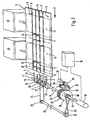
- the conveying fingers 5, 6 of the main chains or main belts 3, 4 project outward in the region of their top strands through outer longitudinal slits 7, 8 of the upper part of the collating path 2, as can be seen from Fig. 2.
- Parallel to and between the main chains or main belts 3, 4 are supported continuous circulating auxiliary chains or auxiliary belts 9, 10 which are equipped with auxiliary fingers 11, 12.
- These auxiliary fingers project above the surface 1 of the collating path in the region of the top strands of the auxiliary chains or auxiliary belts 9, 10 and in pairs define behind them the front ends of respective enclosure compartments 13, 14 with respect to the conveying direction shown by the arrow P.
- Chain wheels or rollers 15 or 16, around which the main chains or main belts 3 or 4 are placed, are used to drive them, and to this end are fastened to a shaft 17. which is rigidly coupled to a drive motor 18, which is supplied with energy in a controlled manner by a control device 19.
- the main chains or main belts 3, 4 are placed around idler chain wheels or idler rollers at the end of the collating path opposite the conveying direction; this is not shown, however, in order to simplify the representation in Fig. 2.
- bearing arrangements for supporting the various shafts or axles of the drive of the enclosure-collating path are quite well known to practitioners of the art.
- Rotatably supported on the shaft 17 is an approximately spool-shaped chain wheel carrier or roller carrier 20, which has one auxiliary chain wheel or one auxiliary roller 21 or 22 on each of its axially front and axially rear end faces.
- auxiliary chain wheels or auxiliary rollers 21 or 22 Placed around the auxiliary chain wheels or auxiliary rollers 21 or 22 are the auxiliary chains or auxiliary belts 9 or 10, which of course are placed around appropriate idler chain wheels or idler rollers in the region of the end of the collating path opposite the conveying direction. This detail is also omitted in the drawing to simplify the representation.
- Placed around the spool-shaped auxiliary chain wheel carrier or auxiliary roller carrier 20 is a drive chain 24, which is guided around a drive chain wheel 25, which sits on an auxiliary drive shaft 26.
- the drive shaft 17 for the main chains or main belts 3 or 4 and the auxiliary drive shaft 26 for driving the auxiliary chains or auxiliary belt 9 or 10 are now coupled together in accordance with the concept specified here such that the mutual separation of the pairs of conveying fingers 5, 6 and the pairs of auxiliary fingers 11, 12 in the conveying direction along the arrow P is greater than the maximum enclosure format in the conveying direction when each enclosure compartment 13, 14 is at a standstill in front of enclosure-ejecting stations, which are schematically indicated in Fig. 2 at A1 and A2, and also in front of an inserter station, not shown in Fig.
- Such a coupling of the drives for the shaft 17 and the auxiliary shaft 26 is achieved in the embodiment in Fig. 2 by means of a differential gear mechanism 27 that is schematically indicated in Fig. 2.
- the differential gear mechanism 27 contains a bevel gear 28 fastened to the shaft 17 and, rotatably supported on the shaft 17, an associated bevel gear 29 with a pulley 30 fastened thereto around which a crossed drive belt 31 is guided to a pulley 32 sitting on the auxiliary shaft 26, wherein the pulleys 30 and 32 have the same effective diameter.
- the spool body of the chain wheel carrier or roller carrier 20 and the chain wheel 25 are also equal in diameter. (Needless to say, the reversal of rotational direction by the aforementioned crossed drive belt 31 can be achieved in many other forms in practical embodiments.)
- Differential bevel gears of the differential gear mechanism 27, one of which is indicated at 33 in Fig. 2, are supported on a carrier ring 34, of which only a small segment is shown in Fig. 2, which has a ring gear 35 in which a drive pinion 36 of a positioning motor 37 engages.
- the positioning motor 37 is supplied with energy in a controlled manner by the control unit 19 such that, by rotating the carrier ring 34 of the differential gear mechanism 27, it is capable of generating specific phase shifts between the shafts 17 and 26, which are otherwise intermittently driven in a synchronous manner by the motor 18.
- actuation of the positioning motor 37 by the control unit 19 when the drive motor 18 is rotating or stopped in such a manner that the differential gear carrier ring 34 is turned counterclockwise with reference to the representation in Fig. 2, has the result that the auxiliary fingers 11, 12 approach the associated conveying fingers 5, 6 of the relevant enclosure compartment 13 or 14 and thus that a shrinking in size of the enclosure compartment occurs relative to the conveying direction, whereas a clockwise rotation of the carrier ring 34 with reference to the representation in Fig. 2 has the result that the auxiliary fingers 11, 12 move away from the associated conveying fingers 5, 6 to enlarge the enclosure compartment 13, 14.
- Fig. 3 shows an embodiment of the enclosure-collating path, with an otherwise identical embodiment to that in Fig. 2, in which the drive shaft 17 for the main chain wheels or main rollers 15, 16 are coupled to a main motor 18, while the auxiliary shaft 26 for driving the auxiliary chain wheels or auxiliary rollers 21, 22 is coupled to a servomotor 40.
- the main motor 18 and the servomotor 40 are provided with energy in a controlled manner by the control unit 19 and, if the motors 18 and 40 are stepper motors for example, receive drive pulses from a common pulse source 41 of the control unit 19. While the main motor 18 is directly supplied with drive pulses from the controlled pulse source 41, the servomotor 40 receives drive pulses 41 through a pulse divider 42 with a finely controllable division ratio.
- control unit 19 provides means for arbitrary phase shift of the drive voltages for the main motor 18 and the servomotor 40 relative to one another.
- Control of the differential gear mechanism 27 and control of the drive voltages for the main motor 18 and the servo motor 40 by the control unit 19 can also be carried out according to an embodiment not shown in the drawings in such a manner that, at least during the phase of decelerating the conveying fingers 5, 6, the auxiliary fingers 11, 12 are located ahead thereof in the conveying direction indicated by the arrow P at a distance corresponding to the maximum enclosure format so as to hold an enclosure stack or an individual enclosure with its trailing edge essentially resting against the front sides of the conveying fingers 5, 6, but then, in any case immediately before the conveying fingers 5, 6 are again accelerated, said auxiliary fingers are advanced in the transverse direction to lie flush next to the conveying fingers 5, 6 of the next enclosure compartment 14, in order for example to assist there in conveying away and accelerating, for example, a catalog placed on an intermediate deck as an enclosure from, for example, the region of the ejecting station A2, together with enclosures located under the intermediate deck, wherein the intermediate deck, which is not shown in the drawing, is designed such that the conveying
- Fig. 4A shows a schematic position-time diagram to illustrate the dimensions of an enclosure compartment between the conveying fingers 5, 6 represented by the path curve 50, and the auxiliary fingers 11, 12 represented by the path curve 51.
- the conveying fingers 5, 6 and the auxiliary fingers 11, 12 had a large separation promoting problem-free enclosure ejection in the .region of the ejecting station A1, they maintain this large separation during the simultaneous and synchronous startup of the conveying fingers and auxiliary fingers at time to through time t 1 .
- the auxiliary fingers 11, 12 are brought to a stop while the conveying fingers continue to move until the time t 2 , thereby reducing the longitudinal dimension of the enclosure compartment to a separation from the auxiliary fingers 11, 12 that corresponds to the maximum dimension of the enclosures in the conveying direction.
- the enclosure compartment is located precisely in the region of the ejecting station A2.
- the drive for the auxiliary fingers 11, 12 is placed in operation again and shortly thereafter is stopped again at time t 4 in such a manner that the enclosure compartment now once again has the large dimension that promotes problem-free ejection of an enclosure, and such problem-free ejection of an enclosure can occur during the period between times t 4 and t 5 .
- the process repeats itself as described above for the period from to to t 4 .
- FIG. 4A An alternative control option is indicated in Fig. 4A by a dotted-and-dashed line 52.
- the path curve 51 can be modified in accordance with the progression along the dotted-and-dashed line 52.
- the path curves 50, 51 and 52 in Fig. 4A are shown in an idealized fashion with discontinuous velocity transitions, In practice, however, the accelerations and decelerations of the conveying fingers 5, 6 and the auxiliary fingers 11, 12 take place with finite values so that the path curves 50, 51, 52 have rounded regions between their straight-line motion segments and their straight-line dwell segments as shown in Fig. 4B. Thus the auxiliary fingers 11, 12 tend to start a deceleration phase at time t 1 , while the conveying fingers 5, 6 are not decelerated until the time t 2 , as per Fig. 4B.
- control by the control unit 19 can also be provided through which both the conveying fingers 5, 6 and the auxiliary fingers 11, 12 simultaneously enter their deceleration phases at time t 2 , wherein however a significantly greater deceleration is provided for the auxiliary fingers 11, 12 such that the distance between the conveying fingers 5, 6 and the auxiliary fingers 11, 12 finally corresponds to the maximum enclosure dimension at time t 3 .
- the invention also concerns collating paths with continuously moving enclosure compartments where such enclosure-collating paths work together with enclosure-ejecting stations, which place or eject enclosures, for example from above, into the enclosure compartments that continuously move under the ejecting stations.
- the invention makes provision to always limit the enclosure compartments to a dimension in the conveying direction corresponding to the maximum enclosure format during the phase of deceleration of the enclosure compartments by means of auxiliary fingers.
- auxiliary fingers are for instance brought to a stop more rapidly than the conveying fingers, or else the auxiliary fingers are braked earlier than the conveying fingers, wherein however care is taken to ensure that the auxiliary fingers and the conveying fingers never approach one another in the conveying direction closer than the dimension specified by the maximum length of the enclosures in the conveying direction.
Landscapes
- Engineering & Computer Science (AREA)
- Mechanical Engineering (AREA)
- Collation Of Sheets And Webs (AREA)
- Separation, Sorting, Adjustment, Or Bending Of Sheets To Be Conveyed (AREA)
Applications Claiming Priority (2)
| Application Number | Priority Date | Filing Date | Title |
|---|---|---|---|
| DE10334099 | 2003-07-25 | ||
| DE10334099A DE10334099B3 (de) | 2003-07-25 | 2003-07-25 | Beilagenzusammentragbahn |
Publications (2)
| Publication Number | Publication Date |
|---|---|
| EP1502889A2 true EP1502889A2 (fr) | 2005-02-02 |
| EP1502889A3 EP1502889A3 (fr) | 2006-05-24 |
Family
ID=32981355
Family Applications (1)
| Application Number | Title | Priority Date | Filing Date |
|---|---|---|---|
| EP04017625A Withdrawn EP1502889A3 (fr) | 2003-07-25 | 2004-07-26 | Appareil d'interclassement de documents |
Country Status (4)
| Country | Link |
|---|---|
| US (1) | US20050062211A1 (fr) |
| EP (1) | EP1502889A3 (fr) |
| CA (1) | CA2475734C (fr) |
| DE (1) | DE10334099B3 (fr) |
Cited By (3)
| Publication number | Priority date | Publication date | Assignee | Title |
|---|---|---|---|---|
| EP1574354A1 (fr) * | 2004-03-10 | 2005-09-14 | Hohner Maschinenbau GmbH | Assembleuse et brocheuse avec deux arbres d'entrainement |
| CN103350051A (zh) * | 2013-06-26 | 2013-10-16 | 东莞美驰图实业有限公司 | 自动涂胶装置 |
| CN111591796A (zh) * | 2020-04-28 | 2020-08-28 | 温州职业技术学院 | 一种柔性印刷机的纸间距调节装置 |
Families Citing this family (11)
| Publication number | Priority date | Publication date | Assignee | Title |
|---|---|---|---|---|
| JP4401986B2 (ja) * | 2005-03-10 | 2010-01-20 | 株式会社東芝 | 画像形成装置、シート搬送方法 |
| JP4468844B2 (ja) * | 2005-03-10 | 2010-05-26 | 株式会社東芝 | 画像形成装置、シート搬送方法 |
| JP4342461B2 (ja) * | 2005-03-10 | 2009-10-14 | 株式会社東芝 | 画像形成装置 |
| JP4429939B2 (ja) * | 2005-03-10 | 2010-03-10 | 株式会社東芝 | 画像形成装置 |
| JP4440146B2 (ja) * | 2005-03-10 | 2010-03-24 | 株式会社東芝 | 画像形成装置 |
| US8079583B2 (en) * | 2008-12-19 | 2011-12-20 | Xerox Corporation | Compiling belt system with moving stapler |
| IT1394525B1 (it) * | 2009-03-05 | 2012-07-05 | Eurosicma S P A | Impianto per l'alimentazione di gruppi di prodotti ad una confezionatrice |
| GB0917626D0 (en) * | 2009-10-08 | 2009-11-25 | Ibis Integrated Bindery System | Book binding apparatus |
| CN103129995B (zh) * | 2013-02-06 | 2016-01-20 | 北京印刷学院 | 一种穿带机的推规输纸装置 |
| JP7014403B2 (ja) * | 2017-11-02 | 2022-02-01 | デュプロ精工株式会社 | シート束搬送装置 |
| DE102021133656A1 (de) * | 2021-12-17 | 2023-06-22 | Homag Bohrsysteme Gmbh | Einrichtung zum Positionieren von Werkstücken, Bearbeitungsmaschine sowie Verfahren zum Positionieren von Werkstücken |
Family Cites Families (8)
| Publication number | Priority date | Publication date | Assignee | Title |
|---|---|---|---|---|
| US893510A (en) * | 1905-07-10 | 1908-07-14 | Charles A Juengst | Signature-gathering machine. |
| US2621039A (en) * | 1947-06-28 | 1952-12-09 | Tw & Cb Sheridan Co | Signature flatwise gathering machine |
| US4502592A (en) * | 1982-02-13 | 1985-03-05 | E.C.H. Will (Gmbh & Co.) | Apparatus for intermittently transporting stacks of paper sheets or the like |
| JPS59190105A (ja) * | 1983-04-13 | 1984-10-27 | Toppan Printing Co Ltd | 物品搬送装置の物品幅変換装置 |
| DE3344114C2 (de) * | 1983-12-07 | 1994-07-14 | Kolbus Gmbh & Co Kg | Zusammentragmaschine |
| US5069326A (en) * | 1989-07-20 | 1991-12-03 | Mazda Motor Corp. | Conveyor means |
| US5279495A (en) * | 1992-11-17 | 1994-01-18 | Bell & Howell Phillipsburg Company | Phase adjustment apparatus for insertion machine |
| US6293544B1 (en) * | 1999-12-22 | 2001-09-25 | Xerox Corporation | Apparatus and method for registering and conveying a compiled set of sheets |
-
2003
- 2003-07-25 DE DE10334099A patent/DE10334099B3/de not_active Expired - Fee Related
-
2004
- 2004-07-21 US US10/895,558 patent/US20050062211A1/en not_active Abandoned
- 2004-07-26 EP EP04017625A patent/EP1502889A3/fr not_active Withdrawn
- 2004-07-26 CA CA002475734A patent/CA2475734C/fr not_active Expired - Fee Related
Cited By (5)
| Publication number | Priority date | Publication date | Assignee | Title |
|---|---|---|---|---|
| EP1574354A1 (fr) * | 2004-03-10 | 2005-09-14 | Hohner Maschinenbau GmbH | Assembleuse et brocheuse avec deux arbres d'entrainement |
| US7407461B2 (en) | 2004-03-10 | 2008-08-05 | Hohner Maschinenbau Gmbh | Gatherer stitcher having two operating shafts |
| CN103350051A (zh) * | 2013-06-26 | 2013-10-16 | 东莞美驰图实业有限公司 | 自动涂胶装置 |
| CN111591796A (zh) * | 2020-04-28 | 2020-08-28 | 温州职业技术学院 | 一种柔性印刷机的纸间距调节装置 |
| CN111591796B (zh) * | 2020-04-28 | 2022-02-18 | 温州职业技术学院 | 一种柔性印刷机的纸间距调节装置 |
Also Published As
| Publication number | Publication date |
|---|---|
| DE10334099B3 (de) | 2004-10-14 |
| CA2475734C (fr) | 2007-10-23 |
| EP1502889A3 (fr) | 2006-05-24 |
| US20050062211A1 (en) | 2005-03-24 |
| CA2475734A1 (fr) | 2005-01-25 |
Similar Documents
| Publication | Publication Date | Title |
|---|---|---|
| CA2475734C (fr) | Dispositif de compilation de documents | |
| US4230218A (en) | Apparatus for transporting layers of sheets | |
| EP0007231B1 (fr) | Dispositif convoyeur pour la mise en lots d'objets | |
| CN101506069B (zh) | 高速传送带上的分布产品的装置 | |
| JP4926322B2 (ja) | コンベヤライン及び/又は包装機械における刊行物のための回転装置 | |
| JPH02261740A (ja) | 板紙の供給装置 | |
| RU2555402C1 (ru) | Устройство для разматывания фольги для пресса для тиснения | |
| US4621966A (en) | Shingle compensating device | |
| JPH0939202A (ja) | 印刷機および該印刷機に用いられる裏返し装置 | |
| JPH0617168B2 (ja) | シート層搬送装置 | |
| EP0789664B1 (fr) | Procede et dispositif de retournement, de mise en sequence et de separation en etages | |
| CA2740834A1 (fr) | Appareil de transport pour enveloppes et procedes apparentes | |
| JPH08113406A (ja) | 紙葉制動装置 | |
| EP1227051B1 (fr) | Procédé et dispositif pour le transport des rames de papier | |
| JPH0629118B2 (ja) | 折り畳み胴から折り畳まれた枚葉紙若しくは折り畳み製品を取り出すための装置 | |
| US5899453A (en) | Document collector, diverter and stager apparatus and method | |
| US4479643A (en) | Method and apparatus for transferring newspapers from pockets to an overlapped stream | |
| US5309697A (en) | Chewing gum packaging machine | |
| US6619650B2 (en) | Device for feeding printed products to a conveying channel | |
| JP2001354348A (ja) | 物品を供給するための装置および方法 | |
| EP0344787B1 (fr) | Méthode et dispositif d'alimentation de signatures à une machine à coudre | |
| JPH08301513A (ja) | シートソーティング装置 | |
| EP1524128B1 (fr) | Dispositif d'assemblage et de mise sous pli, en particulier pour installations de traitement de courrier | |
| EP2189297B1 (fr) | Transport d'enveloppes | |
| JPH03106714A (ja) | ワークの分割供給方法とその装置 |
Legal Events
| Date | Code | Title | Description |
|---|---|---|---|
| PUAI | Public reference made under article 153(3) epc to a published international application that has entered the european phase |
Free format text: ORIGINAL CODE: 0009012 |
|
| AK | Designated contracting states |
Kind code of ref document: A2 Designated state(s): AT BE BG CH CY CZ DE DK EE ES FI FR GB GR HU IE IT LI LU MC NL PL PT RO SE SI SK TR |
|
| AX | Request for extension of the european patent |
Extension state: AL HR LT LV MK |
|
| PUAL | Search report despatched |
Free format text: ORIGINAL CODE: 0009013 |
|
| AK | Designated contracting states |
Kind code of ref document: A3 Designated state(s): AT BE BG CH CY CZ DE DK EE ES FI FR GB GR HU IE IT LI LU MC NL PL PT RO SE SI SK TR |
|
| AX | Request for extension of the european patent |
Extension state: AL HR LT LV MK |
|
| STAA | Information on the status of an ep patent application or granted ep patent |
Free format text: STATUS: THE APPLICATION HAS BEEN WITHDRAWN |
|
| 18W | Application withdrawn |
Effective date: 20061110 |