EP1502899A1 - Wasserkläranlage - Google Patents
Wasserkläranlage Download PDFInfo
- Publication number
- EP1502899A1 EP1502899A1 EP20040394049 EP04394049A EP1502899A1 EP 1502899 A1 EP1502899 A1 EP 1502899A1 EP 20040394049 EP20040394049 EP 20040394049 EP 04394049 A EP04394049 A EP 04394049A EP 1502899 A1 EP1502899 A1 EP 1502899A1
- Authority
- EP
- European Patent Office
- Prior art keywords
- waste treatment
- waste
- housing
- treatment unit
- unit
- Prior art date
- Legal status (The legal status is an assumption and is not a legal conclusion. Google has not performed a legal analysis and makes no representation as to the accuracy of the status listed.)
- Withdrawn
Links
- 238000004065 wastewater treatment Methods 0.000 title 1
- 239000002699 waste material Substances 0.000 claims abstract description 130
- 238000011282 treatment Methods 0.000 claims abstract description 110
- 238000001914 filtration Methods 0.000 claims abstract description 53
- 238000009826 distribution Methods 0.000 claims abstract description 26
- 235000014676 Phragmites communis Nutrition 0.000 claims description 20
- XLYOFNOQVPJJNP-UHFFFAOYSA-N water Substances O XLYOFNOQVPJJNP-UHFFFAOYSA-N 0.000 claims description 17
- 239000012530 fluid Substances 0.000 claims description 7
- 239000000463 material Substances 0.000 claims description 6
- 238000007789 sealing Methods 0.000 claims description 5
- 229910019142 PO4 Inorganic materials 0.000 claims description 3
- 238000011221 initial treatment Methods 0.000 claims description 3
- 235000021317 phosphate Nutrition 0.000 claims description 3
- 150000003013 phosphoric acid derivatives Chemical class 0.000 claims description 3
- 239000004033 plastic Substances 0.000 claims description 3
- 229920003023 plastic Polymers 0.000 claims description 3
- 238000001179 sorption measurement Methods 0.000 claims description 3
- 239000011152 fibreglass Substances 0.000 claims description 2
- 239000011383 glass concrete Substances 0.000 claims description 2
- 239000002184 metal Substances 0.000 claims description 2
- 239000002351 wastewater Substances 0.000 description 24
- 241000196324 Embryophyta Species 0.000 description 7
- 238000009434 installation Methods 0.000 description 5
- 244000273256 Phragmites communis Species 0.000 description 4
- 230000012010 growth Effects 0.000 description 4
- 239000007787 solid Substances 0.000 description 4
- 241000283984 Rodentia Species 0.000 description 3
- 241000238631 Hexapoda Species 0.000 description 2
- 239000000428 dust Substances 0.000 description 2
- 238000012423 maintenance Methods 0.000 description 2
- 230000014759 maintenance of location Effects 0.000 description 2
- 230000003068 static effect Effects 0.000 description 2
- 238000009412 basement excavation Methods 0.000 description 1
- 239000004567 concrete Substances 0.000 description 1
- 238000010276 construction Methods 0.000 description 1
- 238000011109 contamination Methods 0.000 description 1
- 210000002310 elbow joint Anatomy 0.000 description 1
- 230000007613 environmental effect Effects 0.000 description 1
- 238000005429 filling process Methods 0.000 description 1
- 230000005484 gravity Effects 0.000 description 1
- 238000003306 harvesting Methods 0.000 description 1
- 230000002452 interceptive effect Effects 0.000 description 1
- 238000004519 manufacturing process Methods 0.000 description 1
- 239000007769 metal material Substances 0.000 description 1
- 238000000034 method Methods 0.000 description 1
- 230000008635 plant growth Effects 0.000 description 1
- 230000002786 root growth Effects 0.000 description 1
- 238000011144 upstream manufacturing Methods 0.000 description 1
Images



Classifications
-
- C—CHEMISTRY; METALLURGY
- C02—TREATMENT OF WATER, WASTE WATER, SEWAGE, OR SLUDGE
- C02F—TREATMENT OF WATER, WASTE WATER, SEWAGE, OR SLUDGE
- C02F3/00—Biological treatment of water, waste water, or sewage
- C02F3/32—Biological treatment of water, waste water, or sewage characterised by the animals or plants used, e.g. algae
- C02F3/327—Biological treatment of water, waste water, or sewage characterised by the animals or plants used, e.g. algae characterised by animals and plants
-
- C—CHEMISTRY; METALLURGY
- C02—TREATMENT OF WATER, WASTE WATER, SEWAGE, OR SLUDGE
- C02F—TREATMENT OF WATER, WASTE WATER, SEWAGE, OR SLUDGE
- C02F3/00—Biological treatment of water, waste water, or sewage
- C02F3/02—Aerobic processes
- C02F3/04—Aerobic processes using trickle filters
-
- C—CHEMISTRY; METALLURGY
- C02—TREATMENT OF WATER, WASTE WATER, SEWAGE, OR SLUDGE
- C02F—TREATMENT OF WATER, WASTE WATER, SEWAGE, OR SLUDGE
- C02F3/00—Biological treatment of water, waste water, or sewage
- C02F3/02—Aerobic processes
- C02F3/06—Aerobic processes using submerged filters
-
- Y—GENERAL TAGGING OF NEW TECHNOLOGICAL DEVELOPMENTS; GENERAL TAGGING OF CROSS-SECTIONAL TECHNOLOGIES SPANNING OVER SEVERAL SECTIONS OF THE IPC; TECHNICAL SUBJECTS COVERED BY FORMER USPC CROSS-REFERENCE ART COLLECTIONS [XRACs] AND DIGESTS
- Y02—TECHNOLOGIES OR APPLICATIONS FOR MITIGATION OR ADAPTATION AGAINST CLIMATE CHANGE
- Y02W—CLIMATE CHANGE MITIGATION TECHNOLOGIES RELATED TO WASTEWATER TREATMENT OR WASTE MANAGEMENT
- Y02W10/00—Technologies for wastewater treatment
- Y02W10/10—Biological treatment of water, waste water, or sewage
Definitions
- the invention relates to a wastewater or effluent treatment system.
- Wastewater from a domestic treatment device may be passed through a tertiary treatment system such as a filtration system to improve water quality before discharge.
- a reed bed system may be used to further treat the wastewater.
- a problem with current tertiary treatment systems is that they are often extensive and a large site needs to be excavated and prepared for installing the system. In addition the site must be sealed and isolated to prevent contamination of the surrounding area. Due to the requirements for site excavation a tertiary treatment system cannot easily be enlarged or extended should an increased demand arise. Also considerable skill is required in installing and setting up a tertiary treatment system to ensure that it treats the wastewater to the required water quality level before discharge.
- the invention addresses these problems.
- a waste treatment unit for the tertiary treatment of waste comprising a housing having a base and side walls means extending upwardly from the base, a waste inlet, and a waste outlet, wherein the housing comprises first and second internal dividers extending across the housing and connected to the side wall means, the first divider together with the side wall means defining a filtering section, the second divider together with the first divider and the side wall means defining a settlement section, and the second divider together with the side wall means defining a discharge section; the inlet is located at the filtering section and the outlet is located at the discharge section; and the housing further comprises a waste distribution means for receiving waste entering the housing via the inlet and distributing the waste into the filtering section across a dispersed area.
- the invention provides a waste treatment unit divided internally into filtering, settlement and discharge sections.
- This system which is easy to install and effectively takes any guesswork out of laying a tertiary treatment system, since the housing comprises the required internal layout of sections, which are located relative to each other, and configured to optimise treatment of the wastewater prior to discharge into the environment.
- the unit comprises fluid level adjustment means.
- the level adjustment means is movably mounted to the second divider.
- the level adjustment means comprises a pipe.
- the level adjustment means comprises a pipe which is movable between an upper position at which a high water level is maintained in the unit and a lower position at which the water is allowed to drain from the settlement section into the discharge section.
- the pipe is mounted on a swivel joint.
- a waste treatment unit having fluid level adjustment means has the advantage that it allows flexibility in controlling the fluid level which may be raised to help prevent rodent damage, reduce weed growth and encourage spring growth in young plants, and may be lowered when the bed surface becomes dry to reduce insects.
- the inlet is provided in an upper portion of the side wall means.
- the outlet is provided in an upper portion of the side wall means.
- the inlet is located at a level higher than the level of the outlet.
- the inlet and outlet are configured to facilitate connection of the inlet of a similar waste treatment unit to the outlet of the waste treatment unit.
- the first divider is fixed to the housing.
- a sealing means is provided between the first divider and the housing.
- the second divider is fixed to the housing.
- a sealing means is provided between the second divider and the housing.
- the first divider is of mesh.
- the side wall means defines a top opening, wherein the base of the housing is arranged at a slope relative to the top opening such that when the top opening is set substantially level, the base of the housing is set at an orientation to facilitate hydraulic routing of waste through the unit.
- the base of the housing slopes downwardly from the filtering section to the discharge section of the housing to facilitate hydraulic routing of waste through the unit.
- the waste distribution means is fixed to the housing.
- waste distribution means is fixed to the housing at the periphery of the filtering section to distribute waste around the periphery of the filtering section.
- the waste distribution means comprises a form shaped to follow the contour of the side wall means defining the filtering section.
- a waste distribution means configured to receive wastewater entering the housing via the inlet and to distribute the wastewater into the filtering zone has the advantage of facilitating flexibility in locating the inlet to allow for units to be connected together.
- the unit has a substantially rectilinear form defined by rear and front end walls and side walls.
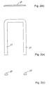
- the waste distribution means comprises a substantially u-shaped form.
- the waste distribution means comprises a trough.
- the trough comprises perforations to allow waste filter into the filtering section.
- the filtering section is configured to contain media for the adsorption of phosphates.
- the filtering section is configured for use as a plant bed or reed bed.
- one or more covering means configured for attachment to the housing to cover one or more of the filtering, settlement and discharge sections or the distribution means.
- the inert material is plastics, glass reinforced plastics, concrete or metal.
- the internal dividers are formed integrally with the housing.
- distribution means is integrally formed with the housing.
- the distribution means comprises attachment means to enable attachment to the housing at the filtering section.
- a waste treatment system comprising at least two of the waste treatment units of the invention connected together.
- the waste treatment system comprises two waste treatment units.
- the waste treatment system comprises more than two waste treatment units.
- the waste treatment system comprises the units are connected together is series.
- the units are connected together with a primary treatment device.
- a first waste treatment unit is configured to allow a second unit to be located at a lower level than the first unit.
- a waste treatment unit 1 comprises a housing 2 having a base 22, rear and front end walls 24, 23 and side walls 25 and 26 extending upwardly from the base 22 to define a top opening or top flange 20.
- the housing 2 comprises an inlet 10 through which waste to be treated enters the housing and an outlet 13 through which treated waste is discharged from the housing.
- First and second internal dividers 11 and 12 connected to the inside of the housing divide it internally into zones or sections, namely, a filtering zone 3, a settlement zone 4 and a discharge zone 5.
- the housing further comprises a waste distribution trough 6 at the filtering zone, which receives wastewater entering via the inlet 10 and distributes the wastewater into the filtering zone 3 of the housing across a dispersed area.
- the filtering zone 3 is filled with washed pea shingle 8 and planted with reeds 9 for use as a reed bed.
- the depth of the housing at the filtering zone is such as to accommodate root growth of reed plants.
- the filtering zone may also be filled with other types of filtering media for different treatments.
- the base 22 of the housing is arranged at a slope relative to the top opening or top flange 20.
- the top opening 20 is arranged substantially horizontally and the base 22 slopes downwardly from the rear end wall 24 of the filtering section to the front end wall 23 of the discharge section.
- the gradient of the base is between 2° and 10°, preferably 3°.
- the base is substantially planar and is configured to provide a hydraulic gradient for the hydraulic routing of waste through the unit.
- the first divider 11 which divides the filtering zone from the settlement zone is comprised of mesh of the order of 2 - 10mm in size, which is fine enough to ensure that gravel does not pass from the filtering zone 3 into the settlement zone 4.
- This divider is connected to the side walls and base of the housing.
- the wall 11 may be connected to the housing by sealing means.
- the second divider 12 which divides the settlement section from the discharge section is a solid wall connected to the housing and sealed to the housing to prevent the ingress of waste from the settlement section to the discharge section where they are connected.
- the dividers 11 and 12 may be integrally formed with the housing, or fixed to the housing during the manufacturing process by mechanical bonding or other suitable means. It will be understood that in another embodiment the housing and dividers 11 and 12 may comprise attachment means to enable them to be assembled together.
- each of the filtering, settlement and discharge zones relative to each other as defined by the location of the internal dividers 11 and 12 provides the required retention time at each of the zones as the wastewater and treated wastewater passes through the zones successively.
- the unit is laid out and designed to facilitate treatment to the required quality levels prior to discharge into the environment.
- the waste treatment unit 1 comprises water level adjustment means comprising a fluid level adjustment pipe 14 which is movably mounted to the divider 12.
- the level adjustment pipe is movable between an upper position at which a high water level is maintained in the unit and a lower position at which the water is allowed to drain from the settlement section into the discharge section.
- the pipe 14 is arranged on a swivel joint. Friction in the joint maintains the pipe at the position to which it is set.
- the pipe may be set at any position between the closed upper position and the open lower position. Fluid level is adjusted by turning the level adjustment pipe 14 to allow wastewater to drain to whatever the new lower level the decanting arm or pipe takes up after turning.
- the level adjustment pipe 14 is arranged on an elbow joint fitting configured to change the flow direction of fluid by 90 degrees in this case.
- the inlet 10 and outlet 13 comprise 110 mm PVCu sockets although it will be understood that sockets of any suitable size may be used with the size of the pipes being selected to correspond.
- Both the inlet 10 and outlet 13 are located near the top flange 20 of the housing, with the outlet being at a lower level than the inlet.
- the outlet 13 is provided at 50 mm below the inlet which in turn is 50mm below the top flange 20.
- the arrangement of the inlet 10 and outlet 13 near the top of the housing 2 facilitates minimal hydraulic headloss across the module and prevents the discharge of solids which are effectively trapped in the housing.
- the wastewater distribution trough 6 is located at the filter zone end of the housing near the top flange 20.
- the trough runs along a section of the interior perimeter housing near the top of the gravel layer.
- the inlet 10 is located in the side wall 25 of the housing. Water passing through the inlet 10 enters the trough 6 which extend along the side wall 25, the end wall 24 and side wall 26.
- the channel of the trough is substantially U-shaped in form.
- the base of the trough comprises perforations through which waste water is dispersed into the filtering zone.
- the housing may be of any suitable shape and the distribution means may comprise a form shaped to follow the contour of the side wall means defining the filtering section.
- the trough is not integrally moulded or cast with the housing but connected to the housing. Different variations of the trough may be provided and fitted to the housing for use in different types of treatments.
- the trough is preformed of dimensions and shape suitable for attachment to the housing.
- the housing and trough comprise attachment means to enable the attachment of the trough thereto.
- the trough is connected to the housing at three sides of the filtering zone. Alternatively the housing may be manufactured with the trough integral thereto.
- the trough 6 enables distribution of wastewater into the filtering zone from different directions, and at the periphery of the filtering zone. Such an arrangement which provides for greater efficiency in filtering the wastewater than is achievable when the effluent enters the filtering zone directly from the inlet pipe.
- the open trough configuration has the advantage that it enables access in the event of a blockage or build up of waste.
- the provision of a waste distribution trough arranged around a portion of the periphery of the filtering zone facilitates the location of the inlet at any point in the side walls or rear end wall of the housing at which the inlet would be connected to the trough. Flexibility in the location of the inlet is desirable when a series of waste treatment units 1 are to be connected end to end or side by side.
- the waste treatment unit 1 further comprises a trough cover 27 for covering the distribution trough 6, and a cover 28 for covering over the settlement and discharge zones.
- the covers are easily fitted and provide increased security by preventing access to wastewater in the trough or the treated effluent in the settlement and discharge zones, the covers also provide protection from frost.
- a further cover 29 (not shown) may also be provided for the filter zone which can be fitted in place to offer protection against frost in winter if the reeds have been harvested or if the unit 1 is being used for treatments other than reed bed treatments.
- the housing 2 is manufactured of an inert rigid material. Any suitable material may be used for example a plastics or metal material, GRP or concrete.
- the housing may be precast or premoulded as an integral unit.
- Removable lifting bolts 21 are provided spaced apart on the top flange 20 to enable handling and lifting of the housing when it is being installed.
- the steps in a method of installing an effluent treatment unit1 of the invention include the following:
- the unit 1 and pipes connecting the inlet and outlet of the unit to adjacent units or to the primary treatment unit are all laid below ground level.
- the outlet is located below ground level to discharge treated waste into the environment below ground level.
- the waste treatment unit is an integral self contained unit which may be supplied as a kit comprising components required for installation for example the housing, trough (if provided separately) and covers. The user only needs to obtain the gravel and reed plants.
- a plurality of waste treatment units 1 of the invention may be installed connected in series to enable handling of different amounts of effluent depending on requirements.
- the outlet 13 is located at a level 50mm below the inlet 10 a fall of 50mm should be allowed between adjacent effluent treatment units 1.
- the outlet 13 of a first effluent treatment unit/reed bed is connected to the inlet 10 of the next.
- a reed bed system comprised of two reed bed units connected in series will typically handle the effluent from up to 6 persons and is appropriate for a single household.
- the waste treatment units 1 may be arranged with the outlet connected directly by means of a short connection pipe to the inlet of the adjacent unit.
- the inlet and outlet may be provided on opposite end walls of the unit in which case a plurality of units 1 in series may be arranged longitudinally end to end.
- the inlet and outlets may be provided in any of the external wall of the housing at the filtering and discharge sections respectively.
- the preformed waste treatment unit of the invention comprising means for defining the internal zones provides a unit in which the locations and relative dimensions of the zones are optimised for treatment of the wastewater prior to discharge into the environment.
- the system effectively takes any guesswork out of laying a tertiary treatment system in that the housing is prefabricated and comprises the required internal layout of sections, configured to provide suitable retention of wastewater at each section to optimise treatment of the wastewater passing therethrough.
- the configuration of the housing is such that is facilitates correct installation for hydraulic routing of waste when the top of the housing is installed at a level, the base is set at the correct orientation for routing the wastewater therethrough.
- the inlet and outlet are located near the top of the unit such that waste filters and flows near the top thereof of the unit in an arrangement which provides protection from short circuiting solids coming across the top of the bed, even in the event of flood or surge conditions.
- the invention provides a low maintenance reed bed system which requires little attention in the first years after installation. Thereafter it may be necessary to thin out the reeds and to harvest them at the end of the growing season.
- the water level of the reed bed unit can be controlled with flexibility and ease by use of the adjustable level adjustment pipe. Adjustment of the pipe allows control of the static water level, which can be raised or lowered as required. When raised the higher water level can prevent rodent damage, reduce weed growth and encourage spring growth in young plants. When lowered the bed surface becomes dry which is often desirable in the summer months to reduce insects.
- the supply of means for effectively controlling the water level reduces requirements for maintenance of the system.
- the unit In use the unit is connected to a primary waste treatment device to treat the waste for release into the environment.
- a primary waste treatment device to treat the waste for release into the environment.
- one or more waste treatment units of the invention may be connected in series to ensure that the waste is treated as required before being released.
- waste treatment system of waste treatment units the invention connected together provides for subsequent expansion of the system to cater for an increased amount of effluent if and as required.
- Further units may be added to a waste treatment system without interfering or needing to restructure the entire existing waste treatment or reed bed system. Should demand or output of effluent upstream from the waste treatment be increased it is possible to install additional waste treatment units in series with an existing waste treatment unit to enable handling of that increased output. It is possible to scale the system based on requirements. Since a larger system is comprised of a plurality of units the present invention provides excellent flexibility in scaling to meet demand.
- each unit effectively has a modular form.
- different media may be used to achieve specific treatment performance objectives for example adsorption of phosphates.
Landscapes
- Life Sciences & Earth Sciences (AREA)
- Engineering & Computer Science (AREA)
- Biotechnology (AREA)
- Botany (AREA)
- Biodiversity & Conservation Biology (AREA)
- Microbiology (AREA)
- Hydrology & Water Resources (AREA)
- Environmental & Geological Engineering (AREA)
- Water Supply & Treatment (AREA)
- Chemical & Material Sciences (AREA)
- Organic Chemistry (AREA)
- Filtration Of Liquid (AREA)
Applications Claiming Priority (2)
| Application Number | Priority Date | Filing Date | Title |
|---|---|---|---|
| IE20030561 | 2003-07-29 | ||
| IE20030561 | 2003-07-29 |
Publications (1)
| Publication Number | Publication Date |
|---|---|
| EP1502899A1 true EP1502899A1 (de) | 2005-02-02 |
Family
ID=32948037
Family Applications (1)
| Application Number | Title | Priority Date | Filing Date |
|---|---|---|---|
| EP20040394049 Withdrawn EP1502899A1 (de) | 2003-07-29 | 2004-07-29 | Wasserkläranlage |
Country Status (2)
| Country | Link |
|---|---|
| EP (1) | EP1502899A1 (de) |
| GB (1) | GB2404656B (de) |
Cited By (2)
| Publication number | Priority date | Publication date | Assignee | Title |
|---|---|---|---|---|
| GB2453149A (en) * | 2007-09-27 | 2009-04-01 | Nigel Arthur Paston | A Reed Bed formed of Reed bed modules |
| EP2371771A1 (de) * | 2010-02-12 | 2011-10-05 | Greener Waste Limited | Modulares Filtrations-Schilfbett |
Families Citing this family (1)
| Publication number | Priority date | Publication date | Assignee | Title |
|---|---|---|---|---|
| GB2472218A (en) * | 2009-07-28 | 2011-02-02 | David Reginald Ward | Clarifier filtration unit |
Citations (4)
| Publication number | Priority date | Publication date | Assignee | Title |
|---|---|---|---|---|
| CH444773A (fr) * | 1967-02-14 | 1967-09-30 | Revilliod Charles | Dispositif pour l'épuration des eaux domestiques |
| US5256281A (en) * | 1991-06-20 | 1993-10-26 | The Lemna Corporation | Baffle system for anaerobic sewage treatment pond |
| US6126827A (en) * | 1993-11-30 | 2000-10-03 | Charles L. Johnson, Jr. | High-strength septage biological treatment system |
| EP1245537A2 (de) * | 2001-03-28 | 2002-10-02 | Marcus Bednarsch | Pflanzenkläranlage |
Family Cites Families (2)
| Publication number | Priority date | Publication date | Assignee | Title |
|---|---|---|---|---|
| SU1758011A1 (ru) * | 1989-04-27 | 1992-08-30 | Севастопольский Приборостроительный Институт | Устройство дл очистки сточных вод |
| GB9100369D0 (en) * | 1991-01-09 | 1991-02-20 | Domnick Hunter Filters Ltd | Apparatus for separating oil from an oil/water mixture |
-
2004
- 2004-07-29 EP EP20040394049 patent/EP1502899A1/de not_active Withdrawn
- 2004-07-29 GB GB0416831A patent/GB2404656B/en not_active Expired - Lifetime
Patent Citations (4)
| Publication number | Priority date | Publication date | Assignee | Title |
|---|---|---|---|---|
| CH444773A (fr) * | 1967-02-14 | 1967-09-30 | Revilliod Charles | Dispositif pour l'épuration des eaux domestiques |
| US5256281A (en) * | 1991-06-20 | 1993-10-26 | The Lemna Corporation | Baffle system for anaerobic sewage treatment pond |
| US6126827A (en) * | 1993-11-30 | 2000-10-03 | Charles L. Johnson, Jr. | High-strength septage biological treatment system |
| EP1245537A2 (de) * | 2001-03-28 | 2002-10-02 | Marcus Bednarsch | Pflanzenkläranlage |
Cited By (3)
| Publication number | Priority date | Publication date | Assignee | Title |
|---|---|---|---|---|
| GB2453149A (en) * | 2007-09-27 | 2009-04-01 | Nigel Arthur Paston | A Reed Bed formed of Reed bed modules |
| GB2453149B (en) * | 2007-09-27 | 2012-07-25 | Nigel Arthur Paston | Reed bed |
| EP2371771A1 (de) * | 2010-02-12 | 2011-10-05 | Greener Waste Limited | Modulares Filtrations-Schilfbett |
Also Published As
| Publication number | Publication date |
|---|---|
| GB0416831D0 (en) | 2004-09-01 |
| GB2404656A (en) | 2005-02-09 |
| GB2404656B (en) | 2006-12-06 |
Similar Documents
| Publication | Publication Date | Title |
|---|---|---|
| US4180348A (en) | Subsurface irrigation and drainage system | |
| US9469981B2 (en) | Fixture cells for bioretention systems | |
| CN106245734A (zh) | 改进的城市道路雨水收集、涵养绿地的调蓄系统 | |
| CN104141346A (zh) | 组合式雨水渗滤树池 | |
| KR100601908B1 (ko) | 우수저류연못을 이용한 비점오염물질 정화 및 친수시설활용방법과 그 장치 | |
| CN106717413B (zh) | 一种海绵城市绿化灌溉系统及其施工方法 | |
| CN217896674U (zh) | 雨水收集灌溉系统 | |
| EP1079682B1 (de) | Wasserabflussverwaltungssystem | |
| GB2404656A (en) | Waste treatment unit including filter and settling tank | |
| CN208064078U (zh) | 一种路堤边坡灌溉系统 | |
| IE20040517A1 (en) | A waste treatment system | |
| KR20190020455A (ko) | 빗물 집수판 및 이를 이용한 집수장치 | |
| IE84656B1 (en) | A waste treatment system | |
| CN215774732U (zh) | 装配式生物滞留自动浇灌设备 | |
| JP2004180529A (ja) | 地下灌漑システム | |
| CN201560492U (zh) | 雨水进水口装置 | |
| JP3839893B2 (ja) | 水田の水位調節装置及び用水管理システム | |
| CN215161884U (zh) | 一种生物滞留设施 | |
| CN113653155A (zh) | 一种海绵城市雨水排水调节系统 | |
| JP2024063319A (ja) | 植栽システム及び桝 | |
| JPH10299068A (ja) | 雨水マスシステム | |
| JP2000050750A (ja) | 棚田における用水の給排水装置 | |
| CN222716151U (zh) | 一种雨水收集的下沉花园 | |
| RU2618091C1 (ru) | Способ устройства осушительно-увлажнительной системы в условиях использования полива дождевальной установкой животноводческими стоками | |
| JPH119122A (ja) | 排水桝及び該排水桝を使用した排水施設の施工方法 |
Legal Events
| Date | Code | Title | Description |
|---|---|---|---|
| PUAI | Public reference made under article 153(3) epc to a published international application that has entered the european phase |
Free format text: ORIGINAL CODE: 0009012 |
|
| AK | Designated contracting states |
Kind code of ref document: A1 Designated state(s): AT BE BG CH CY CZ DE DK EE ES FI FR GB GR HU IE IT LI LU MC NL PL PT RO SE SI SK TR |
|
| AX | Request for extension of the european patent |
Extension state: AL HR LT LV MK |
|
| 17P | Request for examination filed |
Effective date: 20050210 |
|
| AKX | Designation fees paid |
Designated state(s): AT BE BG CH CY CZ DE DK EE ES FI FR GB GR HU IE IT LI LU MC NL PL PT RO SE SI SK TR |
|
| AXX | Extension fees paid |
Extension state: MK Payment date: 20040731 Extension state: LV Payment date: 20040731 Extension state: LT Payment date: 20040731 Extension state: HR Payment date: 20040731 Extension state: AL Payment date: 20040731 |
|
| 17Q | First examination report despatched |
Effective date: 20101110 |
|
| STAA | Information on the status of an ep patent application or granted ep patent |
Free format text: STATUS: THE APPLICATION IS DEEMED TO BE WITHDRAWN |
|
| 18D | Application deemed to be withdrawn |
Effective date: 20130712 |