EP1502973A1 - Vlieskrempel und Verfahren zur Herstellung eines Faservlieses - Google Patents
Vlieskrempel und Verfahren zur Herstellung eines Faservlieses Download PDFInfo
- Publication number
- EP1502973A1 EP1502973A1 EP03017145A EP03017145A EP1502973A1 EP 1502973 A1 EP1502973 A1 EP 1502973A1 EP 03017145 A EP03017145 A EP 03017145A EP 03017145 A EP03017145 A EP 03017145A EP 1502973 A1 EP1502973 A1 EP 1502973A1
- Authority
- EP
- European Patent Office
- Prior art keywords
- conveyor belt
- screen drum
- fiber
- nonwoven
- transport surface
- Prior art date
- Legal status (The legal status is an assumption and is not a legal conclusion. Google has not performed a legal analysis and makes no representation as to the accuracy of the status listed.)
- Granted
Links
Images


Classifications
-
- D—TEXTILES; PAPER
- D04—BRAIDING; LACE-MAKING; KNITTING; TRIMMINGS; NON-WOVEN FABRICS
- D04H—MAKING TEXTILE FABRICS, e.g. FROM FIBRES OR FILAMENTARY MATERIAL; FABRICS MADE BY SUCH PROCESSES OR APPARATUS, e.g. FELTS, NON-WOVEN FABRICS; COTTON-WOOL; WADDING ; NON-WOVEN FABRICS FROM STAPLE FIBRES, FILAMENTS OR YARNS, BONDED WITH AT LEAST ONE WEB-LIKE MATERIAL DURING THEIR CONSOLIDATION
- D04H1/00—Non-woven fabrics formed wholly or mainly of staple fibres or like relatively short fibres
- D04H1/70—Non-woven fabrics formed wholly or mainly of staple fibres or like relatively short fibres characterised by the method of forming fleeces or layers, e.g. reorientation of fibres
- D04H1/74—Non-woven fabrics formed wholly or mainly of staple fibres or like relatively short fibres characterised by the method of forming fleeces or layers, e.g. reorientation of fibres the fibres being orientated, e.g. in parallel (anisotropic fleeces)
-
- D—TEXTILES; PAPER
- D01—NATURAL OR MAN-MADE THREADS OR FIBRES; SPINNING
- D01G—PRELIMINARY TREATMENT OF FIBRES, e.g. FOR SPINNING
- D01G15/00—Carding machines or accessories; Card clothing; Burr-crushing or removing arrangements associated with carding or other preliminary-treatment machines
- D01G15/02—Carding machines
- D01G15/12—Details
- D01G15/46—Doffing or like arrangements for removing fibres from carding elements; Web-dividing apparatus; Condensers
- D01G15/465—Doffing arrangements for removing fibres using, or cooperating with, pneumatic means
-
- D—TEXTILES; PAPER
- D04—BRAIDING; LACE-MAKING; KNITTING; TRIMMINGS; NON-WOVEN FABRICS
- D04H—MAKING TEXTILE FABRICS, e.g. FROM FIBRES OR FILAMENTARY MATERIAL; FABRICS MADE BY SUCH PROCESSES OR APPARATUS, e.g. FELTS, NON-WOVEN FABRICS; COTTON-WOOL; WADDING ; NON-WOVEN FABRICS FROM STAPLE FIBRES, FILAMENTS OR YARNS, BONDED WITH AT LEAST ONE WEB-LIKE MATERIAL DURING THEIR CONSOLIDATION
- D04H1/00—Non-woven fabrics formed wholly or mainly of staple fibres or like relatively short fibres
- D04H1/70—Non-woven fabrics formed wholly or mainly of staple fibres or like relatively short fibres characterised by the method of forming fleeces or layers, e.g. reorientation of fibres
Definitions
- the invention relates to a nonwoven carding for nonwoven production of fiber material according to the preamble of claim 1, and a method for producing a Nonwoven fabric of fibrous material according to the preamble of claim 11.
- Such a fleece card is known, for example, from EP 484 812 A. at This fleece card will be using two fiber removal devices respectively a batt removed from a master cylinder and with the help of compression and Pickup rollers stored on each conveyor belt.
- the conveyor belt of a Fiber removal device transmits a batt on a conveyor belt other fiber removal device, so that finally all the batt on one common conveyor belt can be transported away as a nonwoven.
- EP 817 875 A it is in the case of a plurality of nonwoven carding machines arranged one behind the other known, mechanically the batt of fleece carding on a common continuously deposit in the area of the fleece carded conveyor belt.
- a such plant makes it possible to create high speed carding machines, the production speeds of over 150 m / min, preferably of over 200 m / min up to the range of 400 to 500 m / min, allow.
- the invention is based on the object, the transmission repeatedly removed To improve bobbin on a common conveyor and a more compact Construction of a fleece card to allow.
- each fiber take-off device the removed batt on circumferentially offset transfer sections a circular cylindrical curved, permeable transport surface transfers.
- the peripheral speed of the transport surface is at the transfer speed the batt of the fiber removal device with regard to Direction and amount adjusted, with the transport area at the transfer sections is sucked.
- the invention provides a pick-up system in which a guided transfer of allows individual fibrous webs on a common parallel conveyor belt becomes.
- the circular cylindrical curved, permeable transport surface allows a cheaper storage angle at the transfer sections.
- the curved surfaces at the transfer sections facilitate a detachment of the fibers at the Take-off roller of the fiber removal device in conjunction with the suction of the Transport surface in the area of the transfer sections.
- the superposition of the bastics in short successive transfer sections also allows a better Connection between the upper and lower pile, as well as a compact design the fleece card.
- the circular cylindrical curved transport surface allows a low-distortion transfer of the batt on the conveyor belt, so that higher production speeds possible are.
- the permeable transport surface is formed by a rotating screen drum.
- the screen drum takes over At different transfer sections a plurality of bobbins that together on a transfer point at which the suction flow into the drum at least interrupted is or reversed, on a permeable conveyor belt of a transport device.
- the conveyor belt is at the transfer point between the drum and the Conveyor belt from the transfer point opposite side of the conveyor belt besaugbar.
- a Permeables, endless circulating conveyor belt of a transport device a rotating screen drum at least in the region of the transfer sections of the transport surface wraps around and on top of each other, from the screen drum to the Transport belt sucked in fiber fleece removed.
- the speed is the same the conveyor belt of the peripheral speed of the rotating Screen drum.
- the transport device about one with the axis the screen drum coaxial axis is pivotable, such that the transfer point the conveyor belt for the common batt of the transport device height adjustable on a successor device.
- the fiber removal devices may include at least one with the master cylinder in the Have engaged Dofferwalze.
- the fiber take-off device at least one with the master cylinder having engaging roller which has the batt on at least transfers a doffer roll.
- a fiber removal device or more Fiber removal devices each have a random roller, each having a batt take over from the master cylinder. From the respective random roller of a fiber take-off device For example, the batt can be transferred to one or more doffer rollers become.
- Each doffer roll is preferably with at least one subsequent draft roll and a take-off roll or only a take-off roll engaged.
- the intake device with feed rollers and a lickerin between the lazer and the Master cylinder at least one in the same direction with the master cylinder and the lickerin having rotating impeller.
- the fibers from the licker on at least two ways are transferred to the master cylinder.
- the part of a fleece carding shown in Fig. 1 on the bobbin removal side has a retraction device 2, with the aid of which fibers are transferred to a master cylinder 4 become.
- a possible embodiment of a collection device. 2 with Verwrwalzen 3a, 3b can be seen in Fig. 5.
- Two fiber removal devices 6a, 6b on the fiber pile removal side of the fleece carding each take a batt from the master cylinder 4 and transfer them to a screen drum 14, which forms a circular cylindrical curved permeable transport surface 15 and partially is besaugbar inside, so that an air flow the lateral surface of the Drum 14 flows through in a predetermined segment from the outside to the inside.
- Each fiber take-off device 6a, 6b consists of a doffer roller 8a, 8b and at least a take-off roll 12a, 12b, wherein at least one upsetting roll 10a, 10b be arranged between the doffer roller 8a, 8b and the take-off roller 12a, 12b can.
- the screen drum 14 forms a circular cylindrical curved, permeable transport surface 15, on which the transferred from the fiber take-off device 6a, 6b bobbin at circumferentially offset transfer portions 15a, 15b can be transmitted.
- the transfer sections 15a, 15b are at their narrowest Positions between the take-off rollers 12a, 12b and the transport surface 15. Die Peripheral speed of the screening drum is at its transport surface in the direction and amount to the transfer speed of the batt at the transfer sections 15a, 15b adapted.
- the screen drum 14 is preferably in a segment sucked from the take-off roller 12a to a transfer point between the screening drum 14 and a conveyor belt 16 is sufficient.
- the limit of the sucked Range is indicated in the drawings by angle symbols.
- the advantage of the segmented suction of the screening drum 14 is also that that with lateral sealing of the fiber removal device 6a, 6b only a small Air volume is needed to even at high transport speeds the batt safely transferred to the transfer points.
- the permeable Conveyor belt 16 can at the transfer point 17 between the sieve drum 14 and Transport belt 16 at the bottom have a suction box 18, the Conveyor belt at the transfer point and in a predetermined area behind the transfer point sucks.
- the conveyor belt on its underside between the transfer point between the screen drum and the conveyor belt to a transfer point 20 to a subsequent machine with air vanes Be provided 22, due to the deflection of an air flow below the conveyor belt for a secure adhesion of the batt on the conveyor belt 16 worry.
- Fig. 2 shows an embodiment in which the conveyor belt 16, the screen drum 14 wraps around and at the same speed as the peripheral speed the screen drum 14 is moved.
- the preferred solution avoids another Transfer point between a sieve drum 14 and the conveyor belt 16 and allows thus an even more compact construction of fleece cards.
- Fig. 3 shows an embodiment in which pivotable compression rollers 10a, 10b are shown in a weggeschwenkten position in which they no longer with the doffer rollers 8a, 8b and the take-off rollers 12a, 12b are engaged.
- the compression rollers 6a, 6b can with a suitable pivoting except Be engaged or engaged.
- FIG. 4 shows an exemplary embodiment in which a total of three fiber removal devices 6a, 6b, 6c are provided so that a total of three batts on the endless circulating conveyor belt 16 in conjunction on the common with the sieve drum 14 formed permeable transport surface 15 at transfer points 15a, 15b, 15c can be stored.
- the screen drum 14 can take place segmented also be completely sucked. It is understood that the conveyor belt 16 between the separation point of the screen drum 14 to the transfer point 20 to the following machine also in the embodiments of FIGS. 2 to 7 may have at the bottom air guide vanes 22.
- the transport device with the conveyor belt 16 about the axis of rotation of the drum 14th is pivotable, so that the height of the transfer point 20 to a subsequent Machine is adjustable.
- Louvers 13 e.g. Tubes, as shown in Fig. 4, be arranged to Reduce cross flows.
- Fig. 5 shows an embodiment of a feeder device 2 with a feed roller 2a, a roughing roll 2b and a lickerin 2c.
- two impellers 3a, 3b are arranged between the lazer 2c and the master cylinder 4, two impellers 3a, 3b are arranged.
- the whirl rollers 3a, 3b allow for feeding back to the lickerin, so that the carding performance of the Licker 2c can be used multiple times. It is understood that only one single whip roll 3 with the lickerin 2c and the master cylinder 4 to be engaged can.
- the random rollers 3a, 3b rotate in the same direction with the master cylinder 4 and the Lapturer 2c.
- Fig. 6 shows an embodiment in which the upper fiber take-off device 6a a baffle roller 3c, which is the only roller of the fiber take-off device 6a with the master cylinder 4 is engaged.
- the random roller 3c rotates in the same direction as the master cylinder 4 and in the opposite direction two doffer rollers 8a, 8b engaged with the random roller 3c. To this way, the batt transferred from the master cylinder 4 to the beater roller 3c becomes the bobbin split on two doffer rollers 8a, 8b and from there via take-off rollers 12a, 12b or compression rollers in combination with take-off rollers 12a, 12b on the transport surface 15 of the screen drum 14 and the conveyor belt 16 transmitted.
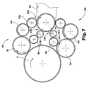
- Fig. 7 shows a further embodiment, wherein the lower fiber take-off device 6b designed in approximately mirror image to the upper fiber take-off device 6a is.
- the lower fiber take-off device 6b therefore has one with the Master cylinder 4 is in engagement engaged roller 3d, which the batt on two Doffer rollers 8c and 8d divides. It is understood that in this embodiment also compression rollers between the doffer rollers 8a to 8d and the doffer rollers 12a to 12d can be arranged.
- the diameter of the master cylinder is about 1,200 to 1,800 mm, preferably 1,500 mm, wherein the diameter of the random rollers between 400 and 700 mm, preferably 550 mm.
Landscapes
- Engineering & Computer Science (AREA)
- Textile Engineering (AREA)
- Preliminary Treatment Of Fibers (AREA)
Abstract
Description
- Fig. 1
- ein erstes Ausführungsbeispiel einer Vlieskrempel mit einer Siebtrommel,
- Fig. 2
- ein zweites Ausführungsbeispiel, bei dem die Siebtrommel von einem permeablen Transportband umgeben ist,
- Fig. 3
- ein Ausführungsbeispiel ohne Stauchwalzen,
- Fig. 4
- ein Ausführungsbeispiel, bei dem drei Faserflore auf das Transportband übertragbar sind, und
- Fig. 5
- eine Einzugseinrichtung der Vlieskrempel,
- Fig. 6
- ein Ausführungsbeispiel mit einer Wirrwalze auf der Florabnahmeseite des Hauptzylinders, und
- Fig. 7
- ein Ausführungsbeispiel mit zwei Wirrwalzen.
Claims (16)
- Vlieskrempel für die Vliesherstellung aus Fasermaterial,dadurch gekennzeichnet, dass jede Faserabnahmeeinrichtung (6a,6b,6c) die abgenommenen Faserflore auf in Umfangsrichtung zueinander versetzte Übergabeabschnitte (15a,15b, 15c,15d) einer kreiszylindrisch gekrümmten permeablen Transportfläche (15) überträgt, deren Umfangsgeschwindigkeit an die Übergabegeschwindigkeit der Faserflore an den Übergabeabschnitten (15a,15b,15c,15d) in Richtung und Betrag angepasst ist, wobei die Übergabeabschnitte der Transportfläche (15) besaugt sind.mit einer Einzugseinrichtung (2),mit mindestens einem Hauptzylinder (4), undmit mehreren Faserabnahmeeinrichtungen (6a,6b,6c) zur Übernahme von mindestens zwei Faserfloren von dem Hauptzylinder (4), wobei die mindestens zwei Faserflore auf ein gemeinsames Transportband einer Transporteinrichtung als Vlies ablegbar sind,
- Vlieskrempel nach Anspruch 1, dadurch gekennzeichnet, dass die permeable Transportfläche (15) auf einer rotierenden Siebtrommel (14) gebildet ist.
- Vlieskrempel nach Anspruch 2, dadurch gekennzeichnet, dass die Transportfläche (15) der Siebtrommel (14) die übernommenen Faserflore an einer Übergabestelle (17) an der der Saugstrom in die Siebtrommel (14) unterbrochen ist oder in einen Blasstrom aus der Siebtrommel (14) umgekehrt ist, auf ein permeables Transportband (16) der Transporteinrichtung überträgt.
- Vlieskrempel nach Anspruch 3, dadurch gekennzeichnet, dass das Transportband (16) unter der Übergabestelle (17) zwischen der Siebtrommel (14) und dem Transportband (16) besaugbar ist.
- Vlieskrempel nach Anspruch 1, dadurch gekennzeichnet, dass ein permeables endlos umlaufendes Transportband (16) einer Transporteinrichtung eine rotierende Siebtrommel (14) zumindest im Bereich der Übergabeabschnitte (15a,15b,15c,15d) der Transportfläche (15) umschlingt und die permeable Transportfläche (15) von dem Transportband (16) und der das Transportband (16) stützenden Siebtrommel (14) gemeinsam gebildet ist.
- Vlieskrempel nach einem der Ansprüche 1 bis 5, dadurch gekennzeichnet, dass die Transporteinrichtung um eine mit der Achse der Siebtrommel (14) koaxiale Achse schwenkbar ist, derart dass die Übergabestelle (20) des Transportbandes (1b) für das Vlies von der Transporteinrichtung auf eine das Vlies weiterverarbeitende nachfolgende Einrichtung höhenverstellbar ist.
- Vlieskrempel nach einem der Ansprüche 1 bis 6, dadurch gekennzeichnet, dass die Faserabnahmeeinrichtungen (6a,6b,6c) mindestens eine mit dem Hauptzylinder (4) im Eingriff befindliche Dofferwalze (8a,8b,8c) aufweisen.
- Vlieskrempel nach einem der Ansprüche 1 bis 6, dadurch gekennzeichnet, dass die Faserabnahmeeinrichtungen (6a,6b,6c) mindestens eine mit dem Hauptzylinder (4) im Eingriff befindliche Wirrwalze (3c,3d) aufweisen, die den Faserflor auf mindestens eine Dofferwalze (8a,8b;8c,8d) überträgt.
- Vlieskrempel nach Anspruch 7 oder 8, dadurch gekennzeichnet, dass jede Dofferwalze (8a,8b,8c,8d) mit mindestens einer nachfolgenden Stauchwalze (10a,10b,10c) oder einer Abnahmewalze (12a,12b,12c,12d) im Eingriff ist.
- Vlieskrempel nach Anspruch 1 bis 9, dadurch gekennzeichnet, dass die Einzugseinrichtung (2) mindestens eine mit dem Hauptzylinder (4) gleichsinnig rotierende Wirrwalze (3a,3b) aufweist.
- Verfahren zum Herstellen eines Vlieses aus Fasermaterialdadurch gekennzeichnet, dass jeder abgenommene Faserflor auf umfangsmäßig zueinander versetzte Übergabeabschnitte (15a,15b,15c,15d) einer permeablen, kreiszylindrisch gekrümmten Transportfläche (15) übertragen wird, wobei die Übergabeabschnitte (15a, 15b, 15c, 15d) an der Transportfläche (15) besaugbar sind und die Umfangsgeschwindigkeit an die Übergabegeschwindigkeit der Faserflore in Richtung und Betrag angepasst sind.durch Zuführen des Fasermaterials über eine Einzugseinrichtung (2) einer Vlieskrempel,durch Kämmen des Fasermaterials auf einem Hauptzylinder (4) der Vlieskrempel,durch Abnehmen von mindestens zwei Faserfloren von dem Hauptzylinder,durch Abtransportieren des aus den Faserfloren gebildeten Vlieses auf einem gemeinsamen Transportband,
- Verfahren nach Anspruch 11, dadurch gekennzeichnet, dass die Transportfläche (15) von einer rotierenden Siebtrommel (14) gebildet wird, von der die abgenommenen Faserflore als Vlies auf ein permeables Transportband (16) übertragen werden.
- Verfahren nach Anspruch 11, dadurch gekennzeichnet, dass die Transportfläche (15) auf einem eine besaugbare und rotierende Siebtrommel (14) umschlingenden permeablen Transportband (16) gebildet wird.
- Verfahren nach einem der Ansprüche 11 bis 13, dadurch gekennzeichnet, dass jeder Faserflor unmittelbar von einer Dofferwalze (8a,8b;8c,8d) oder von einer Wirrwalze (3c,3d) mit nachfolgender Dofferwalze (8a,8b;8c,8d) von dem Hauptzylinder (4) abgenommen wird.
- Verfahren nach Anspruch 14, dadurch gekennzeichnet, dass jeder von einer Wirrwalze (3c,3d) von dem Hautzylinder (4) übernommene Faserflor auf mindestens zwei Dofferwalzen (8a,8b,8c,8d) aufgeteilt wird.
- Verfahren nach einem der Ansprüche 11 bis 13, dadurch gekennzeichnet, dass jeder Faserflor einer Dofferwalze (8a,8b,8c,8d) über eine Abnahmewalze (12a,12b,12c,12d) mit oder ohne Zwischenschaltung einer Stauchwalze (10a,10b,10c,10d) auf die kreiszylindrisch gekrümmte Transportfläche (15) übertragen wird.
Priority Applications (3)
| Application Number | Priority Date | Filing Date | Title |
|---|---|---|---|
| EP03017145A EP1502973B1 (de) | 2003-07-29 | 2003-07-29 | Vlieskrempel und Verfahren zur Herstellung eines Faservlieses |
| DE50308225T DE50308225D1 (de) | 2003-07-29 | 2003-07-29 | Vlieskrempel und Verfahren zur Herstellung eines Faservlieses |
| US10/899,043 US7003853B2 (en) | 2003-07-29 | 2004-07-27 | Intermediate card for manufacturing nonwovens of fibrous material as well as method for manufacturing nonwovens of fibrous material |
Applications Claiming Priority (1)
| Application Number | Priority Date | Filing Date | Title |
|---|---|---|---|
| EP03017145A EP1502973B1 (de) | 2003-07-29 | 2003-07-29 | Vlieskrempel und Verfahren zur Herstellung eines Faservlieses |
Publications (2)
| Publication Number | Publication Date |
|---|---|
| EP1502973A1 true EP1502973A1 (de) | 2005-02-02 |
| EP1502973B1 EP1502973B1 (de) | 2007-09-19 |
Family
ID=33522301
Family Applications (1)
| Application Number | Title | Priority Date | Filing Date |
|---|---|---|---|
| EP03017145A Expired - Lifetime EP1502973B1 (de) | 2003-07-29 | 2003-07-29 | Vlieskrempel und Verfahren zur Herstellung eines Faservlieses |
Country Status (3)
| Country | Link |
|---|---|
| US (1) | US7003853B2 (de) |
| EP (1) | EP1502973B1 (de) |
| DE (1) | DE50308225D1 (de) |
Cited By (1)
| Publication number | Priority date | Publication date | Assignee | Title |
|---|---|---|---|---|
| DE102017117761A1 (de) * | 2017-08-04 | 2019-02-07 | TRüTZSCHLER GMBH & CO. KG | Krempel |
Families Citing this family (5)
| Publication number | Priority date | Publication date | Assignee | Title |
|---|---|---|---|---|
| WO2016142892A1 (en) * | 2015-03-12 | 2016-09-15 | Technoplants S.R.L. | A carding machine |
| WO2016142896A1 (en) * | 2015-03-12 | 2016-09-15 | Technoplants S.R.L. | A carding machine comprising a rotary element |
| FR3081885B1 (fr) * | 2018-05-31 | 2020-09-11 | Andritz Asselin Thibeau | Systeme de formation d’une nappe de fibres |
| ES2953571T3 (es) * | 2019-01-08 | 2023-11-14 | Andritz Perfojet Sas | Instalación y procedimiento de producción de telas no tejidas |
| CN110923945A (zh) * | 2019-07-26 | 2020-03-27 | 浙江兴弘包装材料有限公司 | 一种新型pet热封无纺布成套加工设备及加工工艺 |
Citations (5)
| Publication number | Priority date | Publication date | Assignee | Title |
|---|---|---|---|---|
| GB962162A (en) * | 1960-08-03 | 1964-07-01 | Birfield Eng Ltd | Improvements in or relating to carding engines |
| US5584101A (en) * | 1994-09-30 | 1996-12-17 | Thibeau (Sa) | Apparatus for removing and conveying a fiber web at high speed from the outlet from a carder |
| DE19535876A1 (de) * | 1995-09-27 | 1997-04-03 | Hollingsworth Gmbh | Anlage und Verfahren für die Vliesherstellung aus Fasermaterial |
| EP0837163A1 (de) * | 1996-10-11 | 1998-04-22 | Oskar Dilo Maschinenfabrik KG | Anlage und Verfahren für die Vliesherstellung aus Fasermaterial |
| US20030061686A1 (en) * | 2001-10-03 | 2003-04-03 | Thibeau | Method and installation for the production of a condensed nonwoven and condenser device |
Family Cites Families (7)
| Publication number | Priority date | Publication date | Assignee | Title |
|---|---|---|---|---|
| DE3224118C1 (de) * | 1982-06-29 | 1984-01-26 | Spinnbau GmbH, 2820 Bremen | Krempel zur Vliesherstellung aus Faserstoffen |
| DE3643304C1 (en) * | 1985-09-07 | 1988-03-31 | Spinnbau Gmbh | Card for the production of nonwoven from fibre material |
| IT1241899B (it) | 1990-11-06 | 1994-02-01 | Ma Jersey S P A Fa | Apparecchio per la formazione di un velo a molti strati di fibre randomizzate, e velo ottenuto con detto apparecchio |
| IT1248587B (it) * | 1991-06-28 | 1995-01-19 | Nicola Napolitano | Macchina cardatrice a tamburi,in particolare per la preparazione di tessuti non tessuti e nastri in fibre naturali od artificiali. |
| FR2732042B1 (fr) * | 1995-03-22 | 1997-06-13 | Thibeau & Cie Sa A | Cylindre aspirant permettant le transfert d'un voile fibreux entre un tapis de transport et deux cylindres de calandrage |
| DE19511904B4 (de) | 1995-03-31 | 2006-07-20 | Dilo, Johann Philipp | Anlage und Verfahren zur Herstellung von Vliesbahnen |
| DE19521778A1 (de) * | 1995-06-20 | 1997-01-02 | Hollingsworth Gmbh | Vlieskrempel, sowie Verfahren zur Vliesherstellung |
-
2003
- 2003-07-29 DE DE50308225T patent/DE50308225D1/de not_active Expired - Lifetime
- 2003-07-29 EP EP03017145A patent/EP1502973B1/de not_active Expired - Lifetime
-
2004
- 2004-07-27 US US10/899,043 patent/US7003853B2/en not_active Expired - Fee Related
Patent Citations (5)
| Publication number | Priority date | Publication date | Assignee | Title |
|---|---|---|---|---|
| GB962162A (en) * | 1960-08-03 | 1964-07-01 | Birfield Eng Ltd | Improvements in or relating to carding engines |
| US5584101A (en) * | 1994-09-30 | 1996-12-17 | Thibeau (Sa) | Apparatus for removing and conveying a fiber web at high speed from the outlet from a carder |
| DE19535876A1 (de) * | 1995-09-27 | 1997-04-03 | Hollingsworth Gmbh | Anlage und Verfahren für die Vliesherstellung aus Fasermaterial |
| EP0837163A1 (de) * | 1996-10-11 | 1998-04-22 | Oskar Dilo Maschinenfabrik KG | Anlage und Verfahren für die Vliesherstellung aus Fasermaterial |
| US20030061686A1 (en) * | 2001-10-03 | 2003-04-03 | Thibeau | Method and installation for the production of a condensed nonwoven and condenser device |
Cited By (1)
| Publication number | Priority date | Publication date | Assignee | Title |
|---|---|---|---|---|
| DE102017117761A1 (de) * | 2017-08-04 | 2019-02-07 | TRüTZSCHLER GMBH & CO. KG | Krempel |
Also Published As
| Publication number | Publication date |
|---|---|
| US20050022343A1 (en) | 2005-02-03 |
| EP1502973B1 (de) | 2007-09-19 |
| US7003853B2 (en) | 2006-02-28 |
| DE50308225D1 (de) | 2007-10-31 |
Similar Documents
| Publication | Publication Date | Title |
|---|---|---|
| DE3901313A1 (de) | Vlieskrempel | |
| DE69409648T2 (de) | Vorrichtung zur Abnahme und zum Transportieren mit hoher Geschwindigkeit eines Faservlieses am Ende einer Karde | |
| CH626660A5 (de) | ||
| DE3921399A1 (de) | Verfahren und einrichtung zur herstellung von mineralwollevliesen aus insbesondere steinwolle | |
| DE2830367C2 (de) | Verfahren und Vorrichtung zum Herstellen eines Wirrfaservlieses aus Spinngut, z.B. Wolle, Baumwolle, Chemiefasern u.dgl., mittels eines Krempelvorganges | |
| EP3061855B1 (de) | Krempelanlage und verfahren zur verfestigung mindestens eines faserflors | |
| EP4149751B1 (de) | Anlage zur herstellung eines mehrlagigen vlieses und verfahren zur herstellung eines vlieses | |
| DE102008008549A1 (de) | Vorrichtung zum Herstellen und Verfestigen eines reinen Spinnvlieses | |
| DE69609171T3 (de) | Vorrichtung und gerät für die herstellung von vliesen | |
| AT501434B1 (de) | Vlieszuführvorrichtung | |
| EP1502973B1 (de) | Vlieskrempel und Verfahren zur Herstellung eines Faservlieses | |
| DE10329648B4 (de) | Vorrichtung zur Vliesbildung | |
| EP0777771B1 (de) | Krempel und verfahren zur herstellung eines aerodynamisch gebildeten faserflores | |
| DE10140864A1 (de) | Vorrichtung zum Vernadeln eines förderbaren Faservlieses | |
| DE19923418A1 (de) | Vorrichtung zum Erzeugen eines Vlieses aus Faserflocken, die mindestens einen im wesentlichen vertikalen Schacht von rechteckigem Querschnitt aufweist | |
| EP4461859B1 (de) | Anlage und verfahren zur verbindung bzw. verfestigung einer bahn von faserstoff mit einem vlies | |
| EP3662099B1 (de) | Krempel | |
| EP2872682B1 (de) | Vliesleger | |
| AT501195A1 (de) | Steilarm-vliesleger und vorrichtung zum erzeugen eines kreuzgelegten faservlieses | |
| DD258794A1 (de) | Verfahren und vorrichtung zur herstellung von glasfasererzeugnissen, z. b. vliesen, matten, garnen und vorgarnen | |
| DE19535876A1 (de) | Anlage und Verfahren für die Vliesherstellung aus Fasermaterial | |
| EP3360990B1 (de) | Verfahren zum betrieb eines speichertisches für einen vliesleger | |
| EP2716801B1 (de) | Kreuzleger und Verfahren zum Betreiben eines Kreuzlegers | |
| EP4444946B1 (de) | Anlage und verfahren zur herstellung eines ein- oder mehrlagigen vlieses | |
| DE4234355A1 (de) | Verfahren und Vorrichtung zum Herstellen einer Filzbahn großer Breite |
Legal Events
| Date | Code | Title | Description |
|---|---|---|---|
| PUAI | Public reference made under article 153(3) epc to a published international application that has entered the european phase |
Free format text: ORIGINAL CODE: 0009012 |
|
| AK | Designated contracting states |
Kind code of ref document: A1 Designated state(s): AT BE BG CH CY CZ DE DK EE ES FI FR GB GR HU IE IT LI LU MC NL PT RO SE SI SK TR |
|
| AX | Request for extension of the european patent |
Extension state: AL LT LV MK |
|
| 17P | Request for examination filed |
Effective date: 20050317 |
|
| AKX | Designation fees paid |
Designated state(s): BE DE FR IT |
|
| GRAP | Despatch of communication of intention to grant a patent |
Free format text: ORIGINAL CODE: EPIDOSNIGR1 |
|
| GRAS | Grant fee paid |
Free format text: ORIGINAL CODE: EPIDOSNIGR3 |
|
| GRAA | (expected) grant |
Free format text: ORIGINAL CODE: 0009210 |
|
| AK | Designated contracting states |
Kind code of ref document: B1 Designated state(s): BE DE FR IT |
|
| REF | Corresponds to: |
Ref document number: 50308225 Country of ref document: DE Date of ref document: 20071031 Kind code of ref document: P |
|
| ET | Fr: translation filed | ||
| PLBE | No opposition filed within time limit |
Free format text: ORIGINAL CODE: 0009261 |
|
| STAA | Information on the status of an ep patent application or granted ep patent |
Free format text: STATUS: NO OPPOSITION FILED WITHIN TIME LIMIT |
|
| 26N | No opposition filed |
Effective date: 20080620 |
|
| PGFP | Annual fee paid to national office [announced via postgrant information from national office to epo] |
Ref country code: FR Payment date: 20110729 Year of fee payment: 9 |
|
| PGFP | Annual fee paid to national office [announced via postgrant information from national office to epo] |
Ref country code: DE Payment date: 20110729 Year of fee payment: 9 |
|
| PGFP | Annual fee paid to national office [announced via postgrant information from national office to epo] |
Ref country code: BE Payment date: 20110801 Year of fee payment: 9 Ref country code: IT Payment date: 20110720 Year of fee payment: 9 |
|
| BERE | Be: lapsed |
Owner name: SPINNBAU G.M.B.H. Effective date: 20120731 |
|
| REG | Reference to a national code |
Ref country code: FR Ref legal event code: ST Effective date: 20130329 |
|
| PG25 | Lapsed in a contracting state [announced via postgrant information from national office to epo] |
Ref country code: DE Free format text: LAPSE BECAUSE OF NON-PAYMENT OF DUE FEES Effective date: 20130201 Ref country code: FR Free format text: LAPSE BECAUSE OF NON-PAYMENT OF DUE FEES Effective date: 20120731 |
|
| REG | Reference to a national code |
Ref country code: DE Ref legal event code: R119 Ref document number: 50308225 Country of ref document: DE Effective date: 20130201 |
|
| PG25 | Lapsed in a contracting state [announced via postgrant information from national office to epo] |
Ref country code: IT Free format text: LAPSE BECAUSE OF NON-PAYMENT OF DUE FEES Effective date: 20120729 Ref country code: BE Free format text: LAPSE BECAUSE OF NON-PAYMENT OF DUE FEES Effective date: 20120731 |