EP1503045B1 - Joint actif pour moteurs à turbine - Google Patents
Joint actif pour moteurs à turbine Download PDFInfo
- Publication number
- EP1503045B1 EP1503045B1 EP04254576A EP04254576A EP1503045B1 EP 1503045 B1 EP1503045 B1 EP 1503045B1 EP 04254576 A EP04254576 A EP 04254576A EP 04254576 A EP04254576 A EP 04254576A EP 1503045 B1 EP1503045 B1 EP 1503045B1
- Authority
- EP
- European Patent Office
- Prior art keywords
- seal
- rail
- carrier
- piston
- seal assembly
- Prior art date
- Legal status (The legal status is an assumption and is not a legal conclusion. Google has not performed a legal analysis and makes no representation as to the accuracy of the status listed.)
- Expired - Lifetime
Links
- 239000000969 carrier Substances 0.000 claims description 26
- 239000007789 gas Substances 0.000 description 48
- 239000012530 fluid Substances 0.000 description 16
- 230000001052 transient effect Effects 0.000 description 14
- 238000007789 sealing Methods 0.000 description 12
- 230000000712 assembly Effects 0.000 description 9
- 238000000429 assembly Methods 0.000 description 9
- 230000008901 benefit Effects 0.000 description 4
- 239000000567 combustion gas Substances 0.000 description 4
- 238000004891 communication Methods 0.000 description 4
- 230000008602 contraction Effects 0.000 description 4
- 230000007423 decrease Effects 0.000 description 3
- 238000013461 design Methods 0.000 description 3
- 239000000284 extract Substances 0.000 description 3
- 239000000446 fuel Substances 0.000 description 3
- XKRFYHLGVUSROY-UHFFFAOYSA-N Argon Chemical compound [Ar] XKRFYHLGVUSROY-UHFFFAOYSA-N 0.000 description 2
- IJGRMHOSHXDMSA-UHFFFAOYSA-N Atomic nitrogen Chemical compound N#N IJGRMHOSHXDMSA-UHFFFAOYSA-N 0.000 description 2
- 230000005465 channeling Effects 0.000 description 2
- 230000006835 compression Effects 0.000 description 2
- 238000007906 compression Methods 0.000 description 2
- 238000010276 construction Methods 0.000 description 2
- 238000002955 isolation Methods 0.000 description 2
- 238000012423 maintenance Methods 0.000 description 2
- 239000002184 metal Substances 0.000 description 2
- 239000007787 solid Substances 0.000 description 2
- 238000013022 venting Methods 0.000 description 2
- 229910052786 argon Inorganic materials 0.000 description 1
- 238000006073 displacement reaction Methods 0.000 description 1
- 230000000694 effects Effects 0.000 description 1
- 239000011261 inert gas Substances 0.000 description 1
- 230000014759 maintenance of location Effects 0.000 description 1
- 238000000034 method Methods 0.000 description 1
- 238000012986 modification Methods 0.000 description 1
- 230000004048 modification Effects 0.000 description 1
- 229910052757 nitrogen Inorganic materials 0.000 description 1
- 238000012856 packing Methods 0.000 description 1
- 238000010248 power generation Methods 0.000 description 1
Images




Classifications
-
- F—MECHANICAL ENGINEERING; LIGHTING; HEATING; WEAPONS; BLASTING
- F16—ENGINEERING ELEMENTS AND UNITS; GENERAL MEASURES FOR PRODUCING AND MAINTAINING EFFECTIVE FUNCTIONING OF MACHINES OR INSTALLATIONS; THERMAL INSULATION IN GENERAL
- F16J—PISTONS; CYLINDERS; SEALINGS
- F16J15/00—Sealings
- F16J15/44—Free-space packings
- F16J15/445—Free-space packings with means for adjusting the clearance
-
- F—MECHANICAL ENGINEERING; LIGHTING; HEATING; WEAPONS; BLASTING
- F01—MACHINES OR ENGINES IN GENERAL; ENGINE PLANTS IN GENERAL; STEAM ENGINES
- F01D—NON-POSITIVE DISPLACEMENT MACHINES OR ENGINES, e.g. STEAM TURBINES
- F01D11/00—Preventing or minimising internal leakage of working-fluid, e.g. between stages
- F01D11/02—Preventing or minimising internal leakage of working-fluid, e.g. between stages by non-contact sealings, e.g. of labyrinth type
- F01D11/025—Seal clearance control; Floating assembly; Adaptation means to differential thermal dilatations
-
- F—MECHANICAL ENGINEERING; LIGHTING; HEATING; WEAPONS; BLASTING
- F04—POSITIVE - DISPLACEMENT MACHINES FOR LIQUIDS; PUMPS FOR LIQUIDS OR ELASTIC FLUIDS
- F04D—NON-POSITIVE-DISPLACEMENT PUMPS
- F04D27/00—Control, e.g. regulation, of pumps, pumping installations or pumping systems specially adapted for elastic fluids
- F04D27/02—Surge control
- F04D27/0292—Stop safety or alarm devices, e.g. stop-and-go control; Disposition of check-valves
-
- F—MECHANICAL ENGINEERING; LIGHTING; HEATING; WEAPONS; BLASTING
- F04—POSITIVE - DISPLACEMENT MACHINES FOR LIQUIDS; PUMPS FOR LIQUIDS OR ELASTIC FLUIDS
- F04D—NON-POSITIVE-DISPLACEMENT PUMPS
- F04D29/00—Details, component parts, or accessories
- F04D29/08—Sealings
- F04D29/10—Shaft sealings
- F04D29/102—Shaft sealings especially adapted for elastic fluid pumps
-
- F—MECHANICAL ENGINEERING; LIGHTING; HEATING; WEAPONS; BLASTING
- F16—ENGINEERING ELEMENTS AND UNITS; GENERAL MEASURES FOR PRODUCING AND MAINTAINING EFFECTIVE FUNCTIONING OF MACHINES OR INSTALLATIONS; THERMAL INSULATION IN GENERAL
- F16J—PISTONS; CYLINDERS; SEALINGS
- F16J15/00—Sealings
- F16J15/16—Sealings between relatively-moving surfaces
- F16J15/32—Sealings between relatively-moving surfaces with elastic sealings, e.g. O-rings
- F16J15/3284—Sealings between relatively-moving surfaces with elastic sealings, e.g. O-rings characterised by their structure; Selection of materials
- F16J15/3288—Filamentary structures, e.g. brush seals
-
- F—MECHANICAL ENGINEERING; LIGHTING; HEATING; WEAPONS; BLASTING
- F16—ENGINEERING ELEMENTS AND UNITS; GENERAL MEASURES FOR PRODUCING AND MAINTAINING EFFECTIVE FUNCTIONING OF MACHINES OR INSTALLATIONS; THERMAL INSULATION IN GENERAL
- F16J—PISTONS; CYLINDERS; SEALINGS
- F16J15/00—Sealings
- F16J15/44—Free-space packings
- F16J15/441—Free-space packings with floating ring
- F16J15/442—Free-space packings with floating ring segmented
-
- F—MECHANICAL ENGINEERING; LIGHTING; HEATING; WEAPONS; BLASTING
- F05—INDEXING SCHEMES RELATING TO ENGINES OR PUMPS IN VARIOUS SUBCLASSES OF CLASSES F01-F04
- F05D—INDEXING SCHEME FOR ASPECTS RELATING TO NON-POSITIVE-DISPLACEMENT MACHINES OR ENGINES, GAS-TURBINES OR JET-PROPULSION PLANTS
- F05D2240/00—Components
- F05D2240/55—Seals
- F05D2240/56—Brush seals
-
- F—MECHANICAL ENGINEERING; LIGHTING; HEATING; WEAPONS; BLASTING
- F05—INDEXING SCHEMES RELATING TO ENGINES OR PUMPS IN VARIOUS SUBCLASSES OF CLASSES F01-F04
- F05D—INDEXING SCHEME FOR ASPECTS RELATING TO NON-POSITIVE-DISPLACEMENT MACHINES OR ENGINES, GAS-TURBINES OR JET-PROPULSION PLANTS
- F05D2250/00—Geometry
- F05D2250/10—Two-dimensional
- F05D2250/18—Two-dimensional patterned
- F05D2250/182—Two-dimensional patterned crenellated, notched
-
- F—MECHANICAL ENGINEERING; LIGHTING; HEATING; WEAPONS; BLASTING
- F05—INDEXING SCHEMES RELATING TO ENGINES OR PUMPS IN VARIOUS SUBCLASSES OF CLASSES F01-F04
- F05D—INDEXING SCHEME FOR ASPECTS RELATING TO NON-POSITIVE-DISPLACEMENT MACHINES OR ENGINES, GAS-TURBINES OR JET-PROPULSION PLANTS
- F05D2250/00—Geometry
- F05D2250/10—Two-dimensional
- F05D2250/18—Two-dimensional patterned
- F05D2250/183—Two-dimensional patterned zigzag
-
- F—MECHANICAL ENGINEERING; LIGHTING; HEATING; WEAPONS; BLASTING
- F05—INDEXING SCHEMES RELATING TO ENGINES OR PUMPS IN VARIOUS SUBCLASSES OF CLASSES F01-F04
- F05D—INDEXING SCHEME FOR ASPECTS RELATING TO NON-POSITIVE-DISPLACEMENT MACHINES OR ENGINES, GAS-TURBINES OR JET-PROPULSION PLANTS
- F05D2270/00—Control
- F05D2270/60—Control system actuates means
- F05D2270/62—Electrical actuators
Definitions
- the rotor 14 illustrated in Figure 1 is mounted in various bearings, one of which is indicated schematically below the combustor, and also includes seal assemblies cooperating with the rotor.
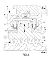
- the seal assembly includes an annular supporting hanger 42 which may have any conventional form for use in gas or steam turbines, for example, yet is suitably modified in accordance with the present invention for providing an active seal. More specifically, the hanger 42 includes a supporting hook or ledge 44 on which is mounted a plurality of arcuate seal segments 46.
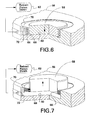
- the bellows is a compression bellows whose inner end 68 is welded to an inner end of the piston 58, and whose outer end 70 is welded to the carrier at an outer end of the bore 60 corresponding with the outer end of the piston 58.
- the height of the piston 58 generally matches the depth of the bore 60 so that the piston is generally flush with the outer surface of the carrier when retracted in the bore.
- the bellows 66 is normally relaxed at its full height with minimal loading and stress therein.
- each carrier 56 preferably includes a plurality of the bores 60 spaced circumferentially apart, with each bore including a respective piston 58 sealed therein by the surrounding bellows 66, the circumferential friction forces are distributed among the several pistons.
- the multiple pistons are preferably grouped near the center of the carrier as illustrated in Figure 5 leaving suitable space between the end pistons and the circumferential ends of the carriers.
- the piston 58 is illustrated retracted flush inside its carrier 56, with the seal segment 46 being seated on the ledges 44 in the radially innermost position.
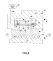
- the actuator 62 illustrated in Figure 8 may then be actuated for delivering the pressurized gas 64 into the carrier for retracting the seal segment radially outwardly as the piston 58 is deployed radially outwardly as shown in phantom line in Figure 8 , and in solid line in Figure 9 .
- the piston is deployed radially outwardly it correspondingly lifts the outer rail 50 relative to the hanger ledges 44, which is permitted by the bottom clearance in the slot 76 through which the carrier is mounted.
Landscapes
- Engineering & Computer Science (AREA)
- General Engineering & Computer Science (AREA)
- Mechanical Engineering (AREA)
- Turbine Rotor Nozzle Sealing (AREA)
- Sealing Devices (AREA)
Claims (10)
- Ensemble (24) d'étanchéité comprenant :un dispositif (42) de suspension annulaire présentant un rebord (44) d'appui ;un segment (46) d'étanchéité arqué présentant un rail (50) radialement extérieur monté sur ledit rebord (44) et supportant un joint (54) radialement intérieur ; etun actionneur (62) permettant de rétracter ledit segment d'étanchéité ;caractérisé par :un transporteur arqué (56) monté entre ledit rebord (44) de dispositif de suspension et ledit rail (50), et présentant un piston (58) monté dans un alésage (60) ;dans lequel ledit actionneur (62) est conçu pour pressuriser ledit alésage (60) afin de déployer ledit piston (58) entre ledit rebord (44) de dispositif de suspension et ledit rail (50).
- Ensemble d'étanchéité selon la revendication 1 comprenant en outre un soufflet tubulaire (66) reliant de manière étanche ledit piston (58) audit transporteur (56) autour dudit alésage (60).
- Ensemble d'étanchéité selon la revendication 2 dans lequel ledit soufflet (66) comprend une extrémité intérieure (68) reliée audit piston (58), et une extrémité extérieure (70) reliée audit transporteur (56) autour dudit alésage (60).
- Ensemble d'étanchéité selon la revendication 3 dans lequel ledit transporteur (56) comprend une pluralité desdits alésages (60) circonférentiellement espacés, et chaque alésage comprend un piston (58) scellé à l'intérieur par un soufflet (66) environnant.
- Ensemble d'étanchéité selon la revendication 3 dans lequel :ledit dispositif (42) de suspension comprend en outre des rebords (44) avant et arrière axialement espacés pour définir une rigole (48) d'appui ;ledit segment (46) d'étanchéité comprend en outre une tige (52) s'étendant vers l'intérieur à partir dudit rail (50) pour supporter ledit joint intérieur (54), et ledit rail (50) relie lesdits rebords avant et arrière dans ladite rigole pour monter ledit segment d'étanchéité dessus ; etledit transporteur (56) est monté entre ledit rail (50) et au moins l'un desdits rebords (44).
- Ensemble d'étanchéité selon la revendication 1 comprenant en outre :un soufflet tubulaire (66) muni d'une extrémité intérieure (68) reliée audit piston (58), et d'une extrémité extérieure (70) reliée audit transporteur (56) autour dudit alésage.
- Ensemble d'étanchéité selon la revendication 6 comprenant en outre :une pluralité desdits segments (46) d'étanchéité montés sur ledit rebord (44) ; etchacun desdits segments comprend un transporteur (56) correspondant muni d'un piston (58) monté dans un alésage (60) et relié de manière collective audit actionneur (62) pour rétracter simultanément lesdits segments d'étanchéité.
- Ensemble d'étanchéité selon la revendication 7 dans lequel :chacun desdits transporteurs (56) comprend une surface extérieure convexe ;lesdits alésages (60) sont disposés à travers lesdites surfaces extérieures convexes ; etlesdits pistons s'étendent radialement vers l'extérieur dans lesdits alésages.
- Ensemble d'étanchéité selon la revendication 8 dans lequel :ledit dispositif (42) de suspension comprend en outre des rebords (44) avant et arrière axialement espacés pour définir une rigole (48) d'appui ;chacun desdits segments d'étanchéité comprend en outre une tige (52) s'étendant vers l'intérieur à partir dudit rail (50) pour supporter ledit joint intérieur (54), et ledit rail (50) relie lesdits rebords avant et arrière dans ladite rigole pour monter lesdits segments d'étanchéité dessus ; etlesdits transporteurs sont montés entre ledit rail (50) et au moins l'un desdits rebords (44).
- Ensemble d'étanchéité selon la revendication 8 dans lequel :ledit dispositif (42) de suspension comprend un rebord avant unique (44) définissant une rigole (48) d'appui ;ledit rail (50) comprend une partie avant montée sur ledit rebord (44), et une partie arrière suspendue à partir de celui-ci ;lesdits transporteurs (56) sont suspendus en-dessous de ladite partie arrière de rail par une pluralité de boulons (80) s'étendant à travers des trous de dégagement dans ledit rail (50) et reliés de manière fixe audit dispositif (42) de suspension ;lesdits transporteurs comprennent des surfaces extérieures convexes ;lesdits alésages sont disposés à travers lesdites surfaces extérieures convexes ; etlesdits pistons s'étendent radialement vers l'extérieur dans lesdits alésages.
Applications Claiming Priority (2)
| Application Number | Priority Date | Filing Date | Title |
|---|---|---|---|
| US632453 | 2000-08-04 | ||
| US10/632,453 US7066470B2 (en) | 2001-12-05 | 2003-07-31 | Active seal assembly |
Publications (3)
| Publication Number | Publication Date |
|---|---|
| EP1503045A2 EP1503045A2 (fr) | 2005-02-02 |
| EP1503045A3 EP1503045A3 (fr) | 2007-04-04 |
| EP1503045B1 true EP1503045B1 (fr) | 2009-06-03 |
Family
ID=33541544
Family Applications (1)
| Application Number | Title | Priority Date | Filing Date |
|---|---|---|---|
| EP04254576A Expired - Lifetime EP1503045B1 (fr) | 2003-07-31 | 2004-07-30 | Joint actif pour moteurs à turbine |
Country Status (4)
| Country | Link |
|---|---|
| US (1) | US7066470B2 (fr) |
| EP (1) | EP1503045B1 (fr) |
| JP (1) | JP2005054790A (fr) |
| DE (1) | DE602004021319D1 (fr) |
Families Citing this family (68)
| Publication number | Priority date | Publication date | Assignee | Title |
|---|---|---|---|---|
| US8919781B2 (en) | 2003-05-01 | 2014-12-30 | Advanced Technologies Group, Inc. | Self-adjusting non-contact seal |
| JP2007521442A (ja) * | 2003-08-26 | 2007-08-02 | ゼネラル・エレクトリック・カンパニイ | 回転機械用シールキャリヤおよび改装方法 |
| US7125223B2 (en) * | 2003-09-30 | 2006-10-24 | General Electric Company | Method and apparatus for turbomachine active clearance control |
| EP1805437B1 (fr) * | 2004-10-22 | 2013-12-04 | Burckhardt Compression AG | Dispositif de garniture de tige de piston fonctionnant a sec et procede pour rendre etanche une tige de piston avec un dispositif de garniture de tige de piston fonctionnant a sec |
| ES2344059T3 (es) * | 2004-12-23 | 2010-08-17 | Siemens Aktiengesellschaft | Disposicion para la obturacion de un intersticio entre un primer componente y un segundo componente. |
| US7334960B2 (en) * | 2005-06-23 | 2008-02-26 | Siemens Power Generation, Inc. | Attachment device for removable components in hot gas paths in a turbine engine |
| US7641200B2 (en) * | 2005-11-28 | 2010-01-05 | General Electric Company | Variable clearance packing ring arrangement |
| US7731478B2 (en) * | 2006-05-25 | 2010-06-08 | General Electric Company | Method and apparatus for variable clearance packing |
| US7549834B2 (en) * | 2006-06-19 | 2009-06-23 | General Electric Company | Actuation pressure control for adjustable seals in turbomachinery |
| US20070295402A1 (en) * | 2006-06-21 | 2007-12-27 | General Electric Company | Pressurized gas supply and control system for actuation of active seals in turbomachinery |
| US20080042367A1 (en) * | 2006-08-17 | 2008-02-21 | General Electric Company | A variable clearance packing ring |
| US8016552B2 (en) * | 2006-09-29 | 2011-09-13 | General Electric Company | Stator—rotor assemblies having surface features for enhanced containment of gas flow, and related processes |
| US20080080972A1 (en) * | 2006-09-29 | 2008-04-03 | General Electric Company | Stationary-rotating assemblies having surface features for enhanced containment of fluid flow, and related processes |
| US7967558B2 (en) * | 2007-01-19 | 2011-06-28 | United Technologies Corporation | Hybrid seal assembly for a fan-turbine rotor of a tip turbine engine |
| US7967559B2 (en) * | 2007-05-30 | 2011-06-28 | General Electric Company | Stator-rotor assembly having surface feature for enhanced containment of gas flow and related processes |
| KR100878460B1 (ko) * | 2007-07-06 | 2009-01-13 | 한국과학기술연구원 | 래비린스 시일 |
| US9297335B2 (en) * | 2008-03-11 | 2016-03-29 | United Technologies Corporation | Metal injection molding attachment hanger system for a cooling liner within a gas turbine engine swivel exhaust duct |
| US7845707B2 (en) * | 2008-03-12 | 2010-12-07 | Gm Global Technology Operations, Inc. | Vehicle closure assembly with shape memory polymer seal |
| JP4898743B2 (ja) * | 2008-06-09 | 2012-03-21 | 三菱重工業株式会社 | 回転機械のシール構造 |
| US8133003B2 (en) * | 2008-09-26 | 2012-03-13 | General Electric Company | Magnetic adjustment of turbomachinery components |
| US8262349B2 (en) * | 2008-12-22 | 2012-09-11 | General Electric Company | Adaptive compliant plate seal assemblies and methods |
| US8113771B2 (en) | 2009-03-20 | 2012-02-14 | General Electric Company | Spring system designs for active and passive retractable seals |
| JP5411569B2 (ja) * | 2009-05-01 | 2014-02-12 | 株式会社日立製作所 | シール構造とその制御方法 |
| US20110156359A1 (en) * | 2009-12-31 | 2011-06-30 | General Electric Company | Turbine engine seals |
| JP5827827B2 (ja) * | 2010-06-29 | 2015-12-02 | エーエスエムエル ネザーランズ ビー.ブイ. | アクチュエータ |
| US8858165B2 (en) | 2010-09-30 | 2014-10-14 | Rolls-Royce Corporation | Seal arrangement for variable vane |
| WO2012129475A2 (fr) * | 2011-03-24 | 2012-09-27 | Dresser-Rand Company | Joint d'étanchéité muni de trous de verrouillage |
| US8454023B2 (en) | 2011-05-10 | 2013-06-04 | General Electric Company | Retractable seal system |
| DE202011105609U1 (de) * | 2011-09-12 | 2011-10-13 | Alstom Technology Ltd. | Labyrinthdichtung |
| JP5922796B2 (ja) * | 2012-12-06 | 2016-05-24 | 三菱重工コンプレッサ株式会社 | シール装置、および、回転機械 |
| EP2971586B1 (fr) * | 2013-03-15 | 2019-11-27 | Dresser-Rand Company | Joint d'étanchéité sans contact auto-ajustant |
| CN103277146A (zh) * | 2013-05-15 | 2013-09-04 | 山东青能动力股份有限公司 | 对称式侧齿汽封结构 |
| WO2015053935A1 (fr) * | 2013-10-11 | 2015-04-16 | United Technologies Corporation | Portée de balai d'étanchéité à inflexion non linéaire |
| US9382801B2 (en) | 2014-02-26 | 2016-07-05 | General Electric Company | Method for removing a rotor bucket from a turbomachine rotor wheel |
| US9429041B2 (en) | 2014-05-14 | 2016-08-30 | General Electric Company | Turbomachine component displacement apparatus and method of use |
| WO2016022136A1 (fr) * | 2014-08-08 | 2016-02-11 | Siemens Energy, Inc. | Système d'optimisation de logement de joint d'étanchéité inter-étage dans un moteur à turbine à gaz |
| CN104632413B (zh) * | 2015-01-30 | 2018-05-01 | 北京华清燃气轮机与煤气化联合循环工程技术有限公司 | 一种燃气轮机燃压缸转静密封结构 |
| ITUB20155442A1 (it) * | 2015-11-11 | 2017-05-11 | Ge Avio Srl | Stadio di un motore a turbina a gas provvisto di una tenuta a labirinto |
| US10279754B2 (en) * | 2016-07-20 | 2019-05-07 | Toyota Motor Engineering & Manufacturing North America, Inc. | Seal for variable dynamic gaps |
| US10697314B2 (en) | 2016-10-14 | 2020-06-30 | Rolls-Royce Corporation | Turbine shroud with I-beam construction |
| US10082039B2 (en) * | 2016-11-02 | 2018-09-25 | United Technologies Corporation | Segmented annular seal |
| US10577032B2 (en) | 2017-05-23 | 2020-03-03 | Toyota Motor Engineering & Manufacturing North America, Inc. | Active seal for dynamic vehicle interface |
| US10427730B2 (en) | 2017-05-25 | 2019-10-01 | Toyota Motor Engineering & Manufacturing North America, Inc. | Active side shield |
| IT201700074311A1 (it) * | 2017-07-03 | 2019-01-03 | Nuovo Pignone Tecnologie Srl | Metodo per fare tenuta, sistema di tenuta e macchina / method of providing sealing, sealing system and machine |
| WO2019045590A1 (fr) * | 2017-08-31 | 2019-03-07 | Siemens Aktiengesellschaft | Agencement d'étanchéité actionné par pression |
| US10458267B2 (en) | 2017-09-20 | 2019-10-29 | General Electric Company | Seal assembly for counter rotating turbine assembly |
| US10711629B2 (en) | 2017-09-20 | 2020-07-14 | Generl Electric Company | Method of clearance control for an interdigitated turbine engine |
| US10557365B2 (en) | 2017-10-05 | 2020-02-11 | Rolls-Royce Corporation | Ceramic matrix composite blade track with mounting system having reaction load distribution features |
| CN108252755A (zh) * | 2018-04-24 | 2018-07-06 | 长兴永能动力科技有限公司 | 一种向心汽轮机用隔板装置 |
| US10968762B2 (en) | 2018-11-19 | 2021-04-06 | General Electric Company | Seal assembly for a turbo machine |
| US11118469B2 (en) | 2018-11-19 | 2021-09-14 | General Electric Company | Seal assembly for a turbo machine |
| US11028713B2 (en) | 2019-04-03 | 2021-06-08 | Raytheon Technologies Corporation | Rotating carbon piston ring seal |
| US11149563B2 (en) | 2019-10-04 | 2021-10-19 | Rolls-Royce Corporation | Ceramic matrix composite blade track with mounting system having axial reaction load distribution features |
| US11428160B2 (en) | 2020-12-31 | 2022-08-30 | General Electric Company | Gas turbine engine with interdigitated turbine and gear assembly |
| US12618473B2 (en) * | 2021-06-22 | 2026-05-05 | Nok Corporation | Sealing ring and sealed structure including same |
| US12006829B1 (en) | 2023-02-16 | 2024-06-11 | General Electric Company | Seal member support system for a gas turbine engine |
| US12486779B2 (en) | 2023-03-08 | 2025-12-02 | General Electric Company | Seal support assembly for a turbine engine |
| US12215587B2 (en) | 2023-03-24 | 2025-02-04 | General Electric Company | Seal support assembly for a turbine engine |
| US12372002B2 (en) | 2023-03-24 | 2025-07-29 | General Electric Company | Seal support assembly for a turbine engine |
| US12421861B2 (en) | 2023-03-24 | 2025-09-23 | General Electric Company | Seal support assembly for a turbine engine |
| US12595745B2 (en) | 2023-03-24 | 2026-04-07 | General Electric Company | Seal support assembly for a turbine engine |
| US12116896B1 (en) | 2023-03-24 | 2024-10-15 | General Electric Company | Seal support assembly for a turbine engine |
| US12241375B2 (en) * | 2023-03-24 | 2025-03-04 | General Electric Company | Seal support assembly for a turbine engine |
| US12416243B2 (en) | 2023-03-24 | 2025-09-16 | General Electric Company | Seal support assembly for a turbine engine |
| US12215588B2 (en) * | 2023-03-27 | 2025-02-04 | General Electric Company | Seal assembly for a gas turbine engine |
| US12326089B2 (en) | 2023-04-24 | 2025-06-10 | General Electric Company | Seal assembly for a gas turbine engine |
| US12404779B1 (en) * | 2024-02-20 | 2025-09-02 | Ge Infrastructure Technology Llc | Axially adjustable inserted ring within packing ring and method of using same |
| CN119801658B (zh) * | 2025-01-09 | 2025-11-21 | 西北工业大学 | 一种含有刷丝衬套的篦齿封严结构 |
Family Cites Families (15)
| Publication number | Priority date | Publication date | Assignee | Title |
|---|---|---|---|---|
| US2279863A (en) * | 1940-09-28 | 1942-04-14 | Gen Electric | Packing arrangement |
| US2279814A (en) * | 1940-12-24 | 1942-04-14 | Gen Electric | Packing arrangement |
| US2614870A (en) * | 1946-10-31 | 1952-10-21 | Allis Chalmers Mfg Co | Turbine diaphragm |
| JPS6116207A (ja) * | 1984-06-30 | 1986-01-24 | Mitsubishi Heavy Ind Ltd | ラビリンスシ−ル装置 |
| US4650340A (en) * | 1985-11-01 | 1987-03-17 | Combustion Engineering, Inc. | Rotating drum end seal |
| US5603510A (en) * | 1991-06-13 | 1997-02-18 | Sanders; William P. | Variable clearance seal assembly |
| ATE230832T1 (de) * | 1999-05-19 | 2003-01-15 | Log Hydraulik Gmbh | Dichtungsvorrichtung für einen mit druckmittel beaufschlagten kolben in einem arbeitszylinder |
| US6435514B1 (en) | 2000-12-15 | 2002-08-20 | General Electric Company | Brush seal with positive adjustable clearance control |
| JP3702212B2 (ja) * | 2001-09-28 | 2005-10-05 | 三菱重工業株式会社 | 軸シール機構及びタービン |
| US6840519B2 (en) * | 2001-10-30 | 2005-01-11 | General Electric Company | Actuating mechanism for a turbine and method of retrofitting |
| US6505834B1 (en) * | 2001-11-02 | 2003-01-14 | General Electric Company | Pressure actuated brush seal |
| US6786487B2 (en) * | 2001-12-05 | 2004-09-07 | General Electric Company | Actuated brush seal |
| US6502823B1 (en) | 2001-12-07 | 2003-01-07 | General Electric Company | Actuating seal carrier for a turbine and method of retrofitting |
| US6572115B1 (en) | 2001-12-21 | 2003-06-03 | General Electric Company | Actuating seal for a rotary machine and method of retrofitting |
| US6655696B1 (en) * | 2002-06-28 | 2003-12-02 | General Electric Company | Seal carrier for a rotary machine and method of retrofitting |
-
2003
- 2003-07-31 US US10/632,453 patent/US7066470B2/en not_active Expired - Fee Related
-
2004
- 2004-07-30 EP EP04254576A patent/EP1503045B1/fr not_active Expired - Lifetime
- 2004-07-30 JP JP2004223007A patent/JP2005054790A/ja active Pending
- 2004-07-30 DE DE602004021319T patent/DE602004021319D1/de not_active Expired - Lifetime
Also Published As
| Publication number | Publication date |
|---|---|
| DE602004021319D1 (de) | 2009-07-16 |
| EP1503045A3 (fr) | 2007-04-04 |
| EP1503045A2 (fr) | 2005-02-02 |
| US20040100035A1 (en) | 2004-05-27 |
| US7066470B2 (en) | 2006-06-27 |
| JP2005054790A (ja) | 2005-03-03 |
Similar Documents
| Publication | Publication Date | Title |
|---|---|---|
| US7066470B2 (en) | Active seal assembly | |
| EP1508671B1 (fr) | Joint à brosses pour une turbomachine | |
| EP0976913B1 (fr) | Turbine à vapeur avec joint d'étanchéité à brosse | |
| US8540479B2 (en) | Active retractable seal for turbo machinery and related method | |
| JP5547997B2 (ja) | 能動的かつ受動的引込み可能シール用のスプリング設計 | |
| CA2481971C (fr) | Methode et dispositif de controle de l'espace nuisible dans une turbomachine | |
| EP1832716B1 (fr) | Dispositif d'étanchéité d'un composant segmenté | |
| EP1832715B1 (fr) | Joint d'étanchéité pour des composants segmentés de turbine à gaz | |
| JP4015586B2 (ja) | 軸シール機構及びこれを備えたタービン、及び、軸シール漏洩防止システム | |
| US20050186079A1 (en) | Gas turbine tip shroud rails | |
| US20090169369A1 (en) | Turbine nozzle segment and assembly | |
| JP2003106105A (ja) | 軸シール機構及びタービン | |
| GB2415230A (en) | Turbo-machinery blade retention plate | |
| EP2199648A1 (fr) | Ensembles et procédés de joint avec plaques adaptatives | |
| GB2038956A (en) | Turbine shroud support structure | |
| US20090014964A1 (en) | Angled honeycomb seal between turbine rotors and turbine stators in a turbine engine | |
| US11208912B2 (en) | Turbine engine with floating shrouds | |
| EP3447343B1 (fr) | Joint à brosse comprenant une plaque de support coulissante | |
| JP2013151936A (ja) | 後付け可能な、段間の傾斜シール | |
| JP2010019261A (ja) | タービンダブテール用のスプリングシール | |
| EP2447475B1 (fr) | Agencement de fixation d'une aube | |
| EP3550185B1 (fr) | Joint à brosse comprenant une plaque de support coulissante | |
| WO2009085580A2 (fr) | Segment de distributeur de turbine et procédé permettant de réparer un segment de distributeur de turbine | |
| WO2010046167A1 (fr) | Agencement de tuyère de turbine à gaz et turbine à gaz | |
| KR102764439B1 (ko) | 마모성 표면 특징부를 갖는 가스터빈 내부 슈라우드 |
Legal Events
| Date | Code | Title | Description |
|---|---|---|---|
| PUAI | Public reference made under article 153(3) epc to a published international application that has entered the european phase |
Free format text: ORIGINAL CODE: 0009012 |
|
| AK | Designated contracting states |
Kind code of ref document: A2 Designated state(s): AT BE BG CH CY CZ DE DK EE ES FI FR GB GR HU IE IT LI LU MC NL PL PT RO SE SI SK TR |
|
| AX | Request for extension of the european patent |
Extension state: AL HR LT LV MK |
|
| PUAL | Search report despatched |
Free format text: ORIGINAL CODE: 0009013 |
|
| AK | Designated contracting states |
Kind code of ref document: A3 Designated state(s): AT BE BG CH CY CZ DE DK EE ES FI FR GB GR HU IE IT LI LU MC NL PL PT RO SE SI SK TR |
|
| AX | Request for extension of the european patent |
Extension state: AL HR LT LV MK |
|
| RIC1 | Information provided on ipc code assigned before grant |
Ipc: F01D 25/16 20060101AFI20040921BHEP Ipc: F16J 15/44 20060101ALI20070227BHEP |
|
| 17P | Request for examination filed |
Effective date: 20071004 |
|
| 17Q | First examination report despatched |
Effective date: 20071107 |
|
| AKX | Designation fees paid |
Designated state(s): DE FR GB |
|
| GRAP | Despatch of communication of intention to grant a patent |
Free format text: ORIGINAL CODE: EPIDOSNIGR1 |
|
| GRAS | Grant fee paid |
Free format text: ORIGINAL CODE: EPIDOSNIGR3 |
|
| GRAA | (expected) grant |
Free format text: ORIGINAL CODE: 0009210 |
|
| AK | Designated contracting states |
Kind code of ref document: B1 Designated state(s): DE FR GB |
|
| REG | Reference to a national code |
Ref country code: GB Ref legal event code: FG4D |
|
| REF | Corresponds to: |
Ref document number: 602004021319 Country of ref document: DE Date of ref document: 20090716 Kind code of ref document: P |
|
| PLBE | No opposition filed within time limit |
Free format text: ORIGINAL CODE: 0009261 |
|
| STAA | Information on the status of an ep patent application or granted ep patent |
Free format text: STATUS: NO OPPOSITION FILED WITHIN TIME LIMIT |
|
| 26N | No opposition filed |
Effective date: 20100304 |
|
| PGFP | Annual fee paid to national office [announced via postgrant information from national office to epo] |
Ref country code: DE Payment date: 20100728 Year of fee payment: 7 Ref country code: FR Payment date: 20100805 Year of fee payment: 7 |
|
| PGFP | Annual fee paid to national office [announced via postgrant information from national office to epo] |
Ref country code: GB Payment date: 20100726 Year of fee payment: 7 |
|
| GBPC | Gb: european patent ceased through non-payment of renewal fee |
Effective date: 20110730 |
|
| REG | Reference to a national code |
Ref country code: FR Ref legal event code: ST Effective date: 20120330 |
|
| PG25 | Lapsed in a contracting state [announced via postgrant information from national office to epo] |
Ref country code: FR Free format text: LAPSE BECAUSE OF NON-PAYMENT OF DUE FEES Effective date: 20110801 Ref country code: DE Free format text: LAPSE BECAUSE OF NON-PAYMENT OF DUE FEES Effective date: 20120201 |
|
| REG | Reference to a national code |
Ref country code: DE Ref legal event code: R119 Ref document number: 602004021319 Country of ref document: DE Effective date: 20120201 |
|
| PG25 | Lapsed in a contracting state [announced via postgrant information from national office to epo] |
Ref country code: GB Free format text: LAPSE BECAUSE OF NON-PAYMENT OF DUE FEES Effective date: 20110730 |