EP1503092B1 - Dichtungsvorrichtung - Google Patents
Dichtungsvorrichtung Download PDFInfo
- Publication number
- EP1503092B1 EP1503092B1 EP20040254341 EP04254341A EP1503092B1 EP 1503092 B1 EP1503092 B1 EP 1503092B1 EP 20040254341 EP20040254341 EP 20040254341 EP 04254341 A EP04254341 A EP 04254341A EP 1503092 B1 EP1503092 B1 EP 1503092B1
- Authority
- EP
- European Patent Office
- Prior art keywords
- bolt
- clip
- barrel
- head
- sealing device
- Prior art date
- Legal status (The legal status is an assumption and is not a legal conclusion. Google has not performed a legal analysis and makes no representation as to the accuracy of the status listed.)
- Expired - Lifetime
Links
- 238000007789 sealing Methods 0.000 title claims description 9
- 210000003128 head Anatomy 0.000 description 16
- 238000003780 insertion Methods 0.000 description 6
- 230000037431 insertion Effects 0.000 description 6
- 229920003023 plastic Polymers 0.000 description 6
- 229910000831 Steel Inorganic materials 0.000 description 5
- 239000002184 metal Substances 0.000 description 5
- 239000004033 plastic Substances 0.000 description 5
- 239000010959 steel Substances 0.000 description 5
- 239000000463 material Substances 0.000 description 4
- 238000006073 displacement reaction Methods 0.000 description 3
- 238000004519 manufacturing process Methods 0.000 description 2
- 229910000639 Spring steel Inorganic materials 0.000 description 1
- 230000006378 damage Effects 0.000 description 1
- 230000003247 decreasing effect Effects 0.000 description 1
- 210000000883 ear external Anatomy 0.000 description 1
- 230000003993 interaction Effects 0.000 description 1
- 238000012986 modification Methods 0.000 description 1
- 230000004048 modification Effects 0.000 description 1
- 239000012858 resilient material Substances 0.000 description 1
Images


Classifications
-
- F—MECHANICAL ENGINEERING; LIGHTING; HEATING; WEAPONS; BLASTING
- F16—ENGINEERING ELEMENTS AND UNITS; GENERAL MEASURES FOR PRODUCING AND MAINTAINING EFFECTIVE FUNCTIONING OF MACHINES OR INSTALLATIONS; THERMAL INSULATION IN GENERAL
- F16B—DEVICES FOR FASTENING OR SECURING CONSTRUCTIONAL ELEMENTS OR MACHINE PARTS TOGETHER, e.g. NAILS, BOLTS, CIRCLIPS, CLAMPS, CLIPS OR WEDGES; JOINTS OR JOINTING
- F16B21/00—Means for preventing relative axial movement of a pin, spigot, shaft or the like and a member surrounding it; Stud-and-socket releasable fastenings
- F16B21/06—Releasable fastening devices with snap-action
- F16B21/07—Releasable fastening devices with snap-action in which the socket has a resilient part
- F16B21/078—Releasable fastening devices with snap-action in which the socket has a resilient part the socket having a further molded-in or embedded component, e.g. a ring with snap-in teeth molded into it
-
- F—MECHANICAL ENGINEERING; LIGHTING; HEATING; WEAPONS; BLASTING
- F16—ENGINEERING ELEMENTS AND UNITS; GENERAL MEASURES FOR PRODUCING AND MAINTAINING EFFECTIVE FUNCTIONING OF MACHINES OR INSTALLATIONS; THERMAL INSULATION IN GENERAL
- F16B—DEVICES FOR FASTENING OR SECURING CONSTRUCTIONAL ELEMENTS OR MACHINE PARTS TOGETHER, e.g. NAILS, BOLTS, CIRCLIPS, CLAMPS, CLIPS OR WEDGES; JOINTS OR JOINTING
- F16B19/00—Bolts without screw-thread; Pins, including deformable elements; Rivets
- F16B19/008—Bolts without screw-thread; Pins, including deformable elements; Rivets with sealing means
-
- F—MECHANICAL ENGINEERING; LIGHTING; HEATING; WEAPONS; BLASTING
- F16—ENGINEERING ELEMENTS AND UNITS; GENERAL MEASURES FOR PRODUCING AND MAINTAINING EFFECTIVE FUNCTIONING OF MACHINES OR INSTALLATIONS; THERMAL INSULATION IN GENERAL
- F16B—DEVICES FOR FASTENING OR SECURING CONSTRUCTIONAL ELEMENTS OR MACHINE PARTS TOGETHER, e.g. NAILS, BOLTS, CIRCLIPS, CLAMPS, CLIPS OR WEDGES; JOINTS OR JOINTING
- F16B2/00—Friction-grip releasable fastenings
- F16B2/20—Clips, i.e. with gripping action effected solely by the inherent resistance to deformation of the material of the fastening
- F16B2/22—Clips, i.e. with gripping action effected solely by the inherent resistance to deformation of the material of the fastening of resilient material, e.g. rubbery material
- F16B2/24—Clips, i.e. with gripping action effected solely by the inherent resistance to deformation of the material of the fastening of resilient material, e.g. rubbery material of metal
- F16B2/248—Clips, i.e. with gripping action effected solely by the inherent resistance to deformation of the material of the fastening of resilient material, e.g. rubbery material of metal of wire
-
- F—MECHANICAL ENGINEERING; LIGHTING; HEATING; WEAPONS; BLASTING
- F16—ENGINEERING ELEMENTS AND UNITS; GENERAL MEASURES FOR PRODUCING AND MAINTAINING EFFECTIVE FUNCTIONING OF MACHINES OR INSTALLATIONS; THERMAL INSULATION IN GENERAL
- F16B—DEVICES FOR FASTENING OR SECURING CONSTRUCTIONAL ELEMENTS OR MACHINE PARTS TOGETHER, e.g. NAILS, BOLTS, CIRCLIPS, CLAMPS, CLIPS OR WEDGES; JOINTS OR JOINTING
- F16B21/00—Means for preventing relative axial movement of a pin, spigot, shaft or the like and a member surrounding it; Stud-and-socket releasable fastenings
- F16B21/10—Means for preventing relative axial movement of a pin, spigot, shaft or the like and a member surrounding it; Stud-and-socket releasable fastenings by separate parts
- F16B21/16—Means for preventing relative axial movement of a pin, spigot, shaft or the like and a member surrounding it; Stud-and-socket releasable fastenings by separate parts with grooves or notches in the pin or shaft
- F16B21/18—Means for preventing relative axial movement of a pin, spigot, shaft or the like and a member surrounding it; Stud-and-socket releasable fastenings by separate parts with grooves or notches in the pin or shaft with circlips or like resilient retaining devices, i.e. resilient in the plane of the ring or the like; Details
- F16B21/186—Means for preventing relative axial movement of a pin, spigot, shaft or the like and a member surrounding it; Stud-and-socket releasable fastenings by separate parts with grooves or notches in the pin or shaft with circlips or like resilient retaining devices, i.e. resilient in the plane of the ring or the like; Details external, i.e. with contracting action
-
- G—PHYSICS
- G09—EDUCATION; CRYPTOGRAPHY; DISPLAY; ADVERTISING; SEALS
- G09F—DISPLAYING; ADVERTISING; SIGNS; LABELS OR NAME-PLATES; SEALS
- G09F3/00—Labels, tag tickets, or similar identification or indication means; Seals; Postage or like stamps
- G09F3/02—Forms or constructions
- G09F3/03—Forms or constructions of security seals
- G09F3/0305—Forms or constructions of security seals characterised by the type of seal used
- G09F3/0317—Forms or constructions of security seals characterised by the type of seal used having bolt like sealing means
-
- F—MECHANICAL ENGINEERING; LIGHTING; HEATING; WEAPONS; BLASTING
- F16—ENGINEERING ELEMENTS AND UNITS; GENERAL MEASURES FOR PRODUCING AND MAINTAINING EFFECTIVE FUNCTIONING OF MACHINES OR INSTALLATIONS; THERMAL INSULATION IN GENERAL
- F16B—DEVICES FOR FASTENING OR SECURING CONSTRUCTIONAL ELEMENTS OR MACHINE PARTS TOGETHER, e.g. NAILS, BOLTS, CIRCLIPS, CLAMPS, CLIPS OR WEDGES; JOINTS OR JOINTING
- F16B41/00—Measures against loss of bolts, nuts, or pins; Measures against unauthorised operation of bolts, nuts or pins
- F16B41/005—Measures against unauthorised operation of bolts, nuts or pins
-
- Y—GENERAL TAGGING OF NEW TECHNOLOGICAL DEVELOPMENTS; GENERAL TAGGING OF CROSS-SECTIONAL TECHNOLOGIES SPANNING OVER SEVERAL SECTIONS OF THE IPC; TECHNICAL SUBJECTS COVERED BY FORMER USPC CROSS-REFERENCE ART COLLECTIONS [XRACs] AND DIGESTS
- Y10—TECHNICAL SUBJECTS COVERED BY FORMER USPC
- Y10T—TECHNICAL SUBJECTS COVERED BY FORMER US CLASSIFICATION
- Y10T292/00—Closure fasteners
- Y10T292/48—Seals
- Y10T292/502—Shiftable catch shackle operated
-
- Y—GENERAL TAGGING OF NEW TECHNOLOGICAL DEVELOPMENTS; GENERAL TAGGING OF CROSS-SECTIONAL TECHNOLOGIES SPANNING OVER SEVERAL SECTIONS OF THE IPC; TECHNICAL SUBJECTS COVERED BY FORMER USPC CROSS-REFERENCE ART COLLECTIONS [XRACs] AND DIGESTS
- Y10—TECHNICAL SUBJECTS COVERED BY FORMER USPC
- Y10T—TECHNICAL SUBJECTS COVERED BY FORMER US CLASSIFICATION
- Y10T292/00—Closure fasteners
- Y10T292/51—Seal bolts
Definitions
- the present invention relates to a sealing or locking device of the type having a main body part into which a bolt is irremovably fitted.
- sealing devices are generally known as bolt seals.
- Bolt seals are generally used for locking doors or containers, in a similar manner to a padlock (the bolt performing the function of the U-shaped hasp of the padlock).
- a padlock the bolt performing the function of the U-shaped hasp of the padlock.
- bolt seals are not intended to be opened by any sort of key. Rather, they are removed by destruction of the seal, in particular by cutting the bolt with a special tool such as a bolt cutter.
- These bolt seals thus provide a secure locking of a door, in particular the door of a container to be transported by lorry, sea or air.
- the seals may be provided with a unique serial number, so that they are tamper evident. Although in most seals the bolt is straight, in some situations it is desired that the bolt has a bent or cranked shape
- a conventional bolt seal is illustrated in Fig. 1 .
- the seal includes a bolt (1) and a body part (2), the body part (2) including a metal barrel (3).
- the bolt (1) has a tapered end (4) behind which is a shoulder (5) forming a narrowed neck (6).
- a wider head (7) At the other end of the bolt is a wider head (7).
- the head (7) and a length of the shank (8) of the bolt will be overmoulded by a plastic sleeve (9).
- the barrel and bolt are both made of steel.
- the cylindrical metal barrel (3) may be overmoulded with a plastic sleeve (10) and this sleeve itself may be provided with a numbered label and then encased in a transparent plastic material.
- the bolt (1) and head (2) can be connected by a short strip (11) which is broken when the seal is to be put into use.
- the barrel (3) is hollow and includes a mouth (12) for receiving the bolt (1). Spaced from the mouth (12) is an annular groove (13) in which can be located a split steel ring (14). It will be understood that the inner diameter of the barrel is sufficient to receive the shank of the bolt. However, the split ring is sized such that it will, in the relaxed position, locate in the groove (13) but in this condition has an inner diameter which is smaller than the diameter of the shank of the bolt. This can be achieved by the split ring being formed of relatively thick wire, or the split ring being deformed so that it is not quite circular. In any event, the ring is resilient and can be forced to adopt a more open condition upon insertion of the bolt.
- the tapered end (4) of the bolt will widen the ring (14), allowing the end of the bolt to pass into the barrel chamber.
- the ring will snap back to its relaxed condition around the neck (6) of the bolt. The bolt is thus locked into the barrel by the ring.
- the seal can now only be opened by destroying the seal, in particular cutting the bolt.
- WO-A-96/05586 discloses a lockable bolt seal which comprises a bolt and a housing. An end portion of the bolt is inserted by sliding into a passage in the housing. A resilient U-shaped locking member made from a bent steel strip is positioned in an inner portion of the passage. The locking member engages with the end portion of the bolt to prevent the bolt from being withdrawn from the passage.
- US-A-5582447 discloses a serpentine shaped wire clip is disposed in a tapered bore of a housing for axial displacement in the bore and has in a preferred embodiment three U-shaped loops interconnnected by end portions.
- the clip has a bore dimensioned for receiving a cable or rod in radial resilient compressive engagement along the clip entire length which engagement causes the clip to axial displace with the displacement of the cable or rod.
- the axial displacement of the clip in the tapered bore wedges the clip to the housing and cable or rod locking the elements.
- the clip may have any number of loops and wire diameter.
- the clip may be locked to smooth and grooved surfaces including threads.
- a sealing device of the type comprising a bolt and a body part for irremovably receiving the shank of a bolt, the body comprising a barrel for receiving the bolt, the bolt having a tapered end and a narrowed portion adjacent the tapered end, with a shoulder formed therebetween, a resilient clip being held within the barrel for locating behind the shoulder of the bolt, characterised in that the clip comprises a single length of wire shaped to form a head and legs connected to the head, the head of the clip being rounded in top view and defining a gap which can open to allow passage of part of the shank of the bolt there-through, the legs extending away from the head so as to locate along the sides and at the bottom of the interior of the barrel.
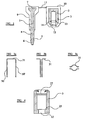
- the bolt (1) of Figs. 2a and 2b is substantially the same as the bolt of the prior art seal. Again, the head and part of the shank are encased in a plastic material (though this is not essential). Figs. 2a and 2b shows a straight bolt, but again this is not essential.
- the bolt of Fig. 2 has behind the tapered end (4) a groove (20), this groove being formed by a short narrowed cross-section of the bolt. Also, between the tapered end (4) and the groove (20) is a short section of the shank which is not tapered, this short section having the same cross-section as the remainder of the shank of the bolt.
- the barrel (3) has a narrowed mouth (12) and a wider chamber portion (26). At the junction of the mouth (12) and the chamber portion (26) is an internal shoulder (25) for location of the clip in the barrel. At the end of the chamber portion (26) remote from the mouth (12) there is located a metal disk (27), formed for example of steel. The ends (28) of the barrel are deformed or swaged over the edge of the disk (27) to fix the disk at the base of the barrel. This is further described in relation to Fig. 4 (see below).
- the metal clip (24) Located within the chamber portion (26) is the metal clip (24). As shown in more detail in Figs. 3a, 3b and 3c , this clip has leg portions (30, 30') joined by a head (31). Head (31) is formed by a pair of spaced wires which close so as to be adjacent to each other at the top of the legs, but form a wider opening in between the legs. As seen in Fig. 3c , the top view of the clip (24) thus shows that the shape is similar to that of an eye. As will be understood from the side view of Fig. 3a , the clip is conveniently formed of one length of wire, the ends of the wire being together at the bottom of one leg and the folded mid-point of the wire forming the end of the other leg. If desired, the clip could be formed of two halves, each with a leg at each side.
- the clip can be formed of any suitable resilient material, typically a steel or spring steel wire of 0.5 to 1.5 mm diameter, for example 1mm diameter.
- the length of the rounded head (31) of the clip is slightly greater than the diameter of the bolt shank.
- the width of this rounded head portion is less than the diameter of the bolt shank so that in use the sides of the head of the clip will locate behind the shoulder (5) of the end of the bolt. It will be understood that on insertion of the bolt, the tapered end (4) will push apart the sides of the head (31) of the clip, thus forcing the clip to widen to allow passage of the end (4). However, as soon as the head has passed the clip, the clip will snap into the groove (20) thus fixing the bolt in the chamber.
- the clip is fixed in the barrel by locating behind an internal shoulder (25), other arrangements are possible.
- the resilient clip may have outer ears or prongs which would snap into an internal groove of the barrel.
- the described shoulder of the barrel will provide the most positive resistance to the bolt being pulled out, after it is captured by the clip.
- the length of the legs (30, 30') of the clip are chosen so that on fixing of the disk (27) the clip is located in the barrel so that excessive movement of the clip along the length of the barrel is not possible.
- the clip has to have a degree of looseness so that it can flex apart to allow insertion of the bolt.
- the disk (27) is then inserted into the end of the barrel, preferably seating on an annular shoulder, at a position adjacent the ends of the arms (30, 30') of the clip (although insertion of the disk may push the clip in further, if it is not yet fully inserted).
- the ends of the barrel are then deformed or swaged on top of the disk, to fix it in place.
- the barrel can then be overmoulded in plastic material, in a conventional fashion. It will be understood that in addition to the easy and reliable fitting of the clip into the barrel, the barrel itself can also be formed more easily due to its simplified cross-section as compared to the prior art barrels.
- the barrel can be formed as in the prior art ( Fig.1 ) and the clip can be inserted from the top, using a dedicated tool.
- the invention can thus provide an improved bolt seal in which a very efficient locking of the bolt into the barrel is achieved through the flexing sides of the head of the clip.
- the clip can also be fitted in the barrel in a reliable and efficient manner, thus improving the security of the seal and decreasing manufacturing costs.
Landscapes
- Engineering & Computer Science (AREA)
- General Engineering & Computer Science (AREA)
- Mechanical Engineering (AREA)
- Computer Security & Cryptography (AREA)
- Physics & Mathematics (AREA)
- General Physics & Mathematics (AREA)
- Theoretical Computer Science (AREA)
- Gasket Seals (AREA)
- Clamps And Clips (AREA)
- Securing Of Glass Panes Or The Like (AREA)
- Closures For Containers (AREA)
- Seal Device For Vehicle (AREA)
Claims (4)
- Plombiervorrichtung jener Art, die einen Bolzen (1) und einen Körperteil (2) zur unlösbaren Aufnahme des Schafts eines Bolzens umfasst, wobei der Körper einen Zylinder (3) zur Aufnahme des Bolzens (1) umfasst, wobei der Bolzen ein konisch zulaufendes Ende (4) und einen verschmälerten Teil (20) neben dem konisch zulaufenden Ende aufweist, wobei dazwischen eine Schulter (5) ausgebildet ist, wobei eine elastische Klemme (24) in dem Zylinder zur Anordnung hinter der Schulter (5) des Bolzens gehalten wird, dadurch gekennzeichnet, dass die Klemme (24) eine einzelne Drahtlänge umfasst, die zum Bilden eines Kopfs (31) und von Schenkeln (30, 30'), die mit dem Kopf verbunden sind, geformt ist, wobei der Kopf (31) der Klemme in Draufsicht abgerundet ist und einen Spalt definiert, der sich öffnen kann, um einen Teil des Schafts (8) des Bolzens dadurch durchzulassen, wobei sich die Schenkel (30, 30') von dem Kopf (31) weg erstrecken, um entlang den Seiten und am Boden des Innenraums des Zylinders (3) angeordnet zu werden.
- Plombiervorrichtung nach Anspruch 1, wobei der Boden des Zylinders (3) aus einem getrennten Element (27) gebildet ist, so dass die Klemme (24) von unten eingeführt werden kann, wenn das Element anschließend angeordnet wird.
- Plombiervorrichtung nach Anspruch 1 oder 2, wobei der Kopf (31) der Klemme hinter einer Schulter (25) angeordnet wird, die in der Mündung des Zylinders ausgebildet ist.
- Plombiervorrichtung nach einem der vorhergehenden Ansprüche, wobei die Schenkel (30, 30') der Klemme jeweils durch parallele Längen der einzelnen Drahtlänge gebildet werden, die die Klemme (24) bildet.
Applications Claiming Priority (2)
| Application Number | Priority Date | Filing Date | Title |
|---|---|---|---|
| GB0317840A GB0317840D0 (en) | 2003-07-30 | 2003-07-30 | Sealing device |
| GB0317840 | 2003-07-30 |
Publications (3)
| Publication Number | Publication Date |
|---|---|
| EP1503092A2 EP1503092A2 (de) | 2005-02-02 |
| EP1503092A3 EP1503092A3 (de) | 2006-01-25 |
| EP1503092B1 true EP1503092B1 (de) | 2009-03-18 |
Family
ID=27799482
Family Applications (1)
| Application Number | Title | Priority Date | Filing Date |
|---|---|---|---|
| EP20040254341 Expired - Lifetime EP1503092B1 (de) | 2003-07-30 | 2004-07-20 | Dichtungsvorrichtung |
Country Status (7)
| Country | Link |
|---|---|
| US (1) | US7226095B2 (de) |
| EP (1) | EP1503092B1 (de) |
| CN (1) | CN100343466C (de) |
| DE (1) | DE602004020029D1 (de) |
| ES (1) | ES2323062T3 (de) |
| GB (1) | GB0317840D0 (de) |
| RU (1) | RU2276716C2 (de) |
Families Citing this family (21)
| Publication number | Priority date | Publication date | Assignee | Title |
|---|---|---|---|---|
| US20080143123A1 (en) * | 2005-05-31 | 2008-06-19 | Dewalch Norman Binz | Locking apparatus and method |
| AU2008261557A1 (en) * | 2007-06-15 | 2008-12-18 | Matthew Henderson | A transponder bolt seal and a housing for a transponder |
| US9472125B2 (en) * | 2007-10-05 | 2016-10-18 | E.J. Brooks Company | Reusable bolt electronic seal module with GPS/cellular phone communications and tracking system |
| US20090320540A1 (en) * | 2008-06-30 | 2009-12-31 | E. J. Brooks Company | Bolt seal |
| US20090320541A1 (en) * | 2008-06-30 | 2009-12-31 | E. J. Brooks Company | Bolt seal |
| JP5049921B2 (ja) * | 2008-08-26 | 2012-10-17 | キヤノン株式会社 | 画像処理装置及び画像処理方法 |
| TWM407942U (en) * | 2011-01-20 | 2011-07-21 | wen-he Cai | Identification structure for breakage of sealed lock |
| US20130020337A1 (en) * | 2011-07-20 | 2013-01-24 | Yi-An Lai | Container seal |
| US8733805B2 (en) | 2011-07-27 | 2014-05-27 | Nic Products Inc. | Security seal assembly |
| WO2013148013A1 (en) | 2012-03-27 | 2013-10-03 | E. J. Brooks Company | Tamper evident bolt security seal |
| EP2839453B1 (de) * | 2012-04-19 | 2016-08-31 | Ian Nazzari | Riegel |
| CN102913517B (zh) * | 2012-11-01 | 2014-07-30 | 慧明光电(深圳)有限公司 | 一种同轴可收紧自动锁 |
| BR202012031675U2 (pt) * | 2012-12-12 | 2014-11-11 | Plasticos Polyvig Ltda | Disposição construtiva aplicada em lacre de segurança |
| FR3000771B1 (fr) * | 2013-01-10 | 2015-02-13 | Raymond A & Cie | Agrafe de fixation d'un panneau sur un support et assemblage obtenu |
| MX362179B (es) | 2013-05-14 | 2019-01-08 | Nic Products Inc | Sello de seguridad giratorio. |
| US10186176B2 (en) | 2013-05-14 | 2019-01-22 | Nic Products, Inc. | Rotary security seal |
| USD720215S1 (en) * | 2013-06-19 | 2014-12-30 | Mega Fortis (Malaysia) Sdn. Bhd. | Container seal |
| US20150061303A1 (en) * | 2013-08-27 | 2015-03-05 | Novavision, Inc. | Bolt Security Seal |
| WO2016081832A1 (en) * | 2014-11-21 | 2016-05-26 | Nic Products Inc. | Security lock bolt assembly |
| KR200483509Y1 (ko) * | 2016-09-25 | 2017-05-23 | 권애경 | 기념 이벤트용 자물쇠 |
| CN110480218A (zh) * | 2019-08-09 | 2019-11-22 | 唐山英莱科技有限公司 | 一种高精度视觉传感器快换卡具 |
Family Cites Families (19)
| Publication number | Priority date | Publication date | Assignee | Title |
|---|---|---|---|---|
| US970529A (en) * | 1910-01-03 | 1910-09-20 | John J A Miller | Seal for car-doors, shipping-receptacles, &c. |
| US1001878A (en) * | 1910-08-15 | 1911-08-29 | Harpoon Seal Company | Seal for car-doors, shipping-receptacles, &c. |
| US1397101A (en) * | 1920-02-16 | 1921-11-15 | Walter J Kelly | Metallic seal |
| US1943988A (en) * | 1932-03-22 | 1934-01-16 | Kilgore Mfg Co | Lock |
| CH188941A (de) * | 1936-11-28 | 1937-01-31 | Weber Hans | Klemme zum Festklemmen von Zugorganen. |
| US2319753A (en) * | 1940-07-05 | 1943-05-18 | Thomas F Smith | Lock |
| DE2028672A1 (de) * | 1970-06-11 | 1971-12-23 | Gesellschaft für Kernforschung mbH, 7500 Karlsruhe | Verfahren zur Identifizierung von Angriffen auf selbstschließende Sicherheitssiegel |
| DK134811A (de) * | 1974-02-05 | 1900-01-01 | ||
| US4779911A (en) * | 1987-03-04 | 1988-10-25 | Wu Brown W | Padlock seal |
| US5005883A (en) * | 1990-05-24 | 1991-04-09 | E. J. Brooks Company | Tamper indicator for a locking seal |
| JPH05256056A (ja) * | 1992-03-11 | 1993-10-05 | Hori Lock Kogyo Kk | 封緘錠 |
| RU2060561C1 (ru) * | 1993-03-04 | 1996-05-20 | Виктор Владимирович Крылов | Пломба |
| GB9416482D0 (en) | 1994-08-16 | 1994-10-12 | Envopak Group Ltd | Lockable seal |
| RU2075111C1 (ru) * | 1994-10-26 | 1997-03-10 | Акционерное общество закрытого типа "Страж" | Пломба-запор |
| US5582447A (en) * | 1995-02-24 | 1996-12-10 | E. J. Brooks Company | Locking device with serpentine gripping member |
| CN2283699Y (zh) * | 1997-01-29 | 1998-06-10 | 沈阳兴港施封锁有限公司 | 施封锁 |
| CN2364004Y (zh) | 1999-03-30 | 2000-02-16 | 沈阳铁路分局施封锁制造公司 | 一种集装箱施封锁 |
| US6265973B1 (en) * | 1999-04-16 | 2001-07-24 | Transguard Industries, Inc. | Electronic security seal |
| US6550829B1 (en) * | 2000-02-09 | 2003-04-22 | Dobson Dewayne L. | Cargo security seal |
-
2003
- 2003-07-30 GB GB0317840A patent/GB0317840D0/en not_active Ceased
-
2004
- 2004-07-06 RU RU2004120676A patent/RU2276716C2/ru not_active IP Right Cessation
- 2004-07-12 US US10/888,581 patent/US7226095B2/en not_active Expired - Fee Related
- 2004-07-20 ES ES04254341T patent/ES2323062T3/es not_active Expired - Lifetime
- 2004-07-20 EP EP20040254341 patent/EP1503092B1/de not_active Expired - Lifetime
- 2004-07-20 DE DE200460020029 patent/DE602004020029D1/de not_active Expired - Lifetime
- 2004-07-30 CN CNB2004100556470A patent/CN100343466C/zh not_active Expired - Fee Related
Also Published As
| Publication number | Publication date |
|---|---|
| ES2323062T3 (es) | 2009-07-06 |
| CN100343466C (zh) | 2007-10-17 |
| RU2276716C2 (ru) | 2006-05-20 |
| CN1576503A (zh) | 2005-02-09 |
| GB0317840D0 (en) | 2003-09-03 |
| US20050023844A1 (en) | 2005-02-03 |
| EP1503092A3 (de) | 2006-01-25 |
| EP1503092A2 (de) | 2005-02-02 |
| US7226095B2 (en) | 2007-06-05 |
| RU2004120676A (ru) | 2006-01-10 |
| DE602004020029D1 (de) | 2009-04-30 |
Similar Documents
| Publication | Publication Date | Title |
|---|---|---|
| EP1503092A2 (de) | Dichtungsvorrichtung | |
| US3290080A (en) | Breakable seal | |
| JP5178744B2 (ja) | 一体型セキュリティシール | |
| US5603532A (en) | Grab rings | |
| US4588218A (en) | Security seal | |
| US8960737B2 (en) | Lock bolt | |
| US20160146239A1 (en) | Security Lock Bolt Assembly | |
| US5884949A (en) | Security seal | |
| EA002552B1 (ru) | Самофиксирующаяся проволочная пломба и способ опломбирования объекта с ее использованием | |
| US20050230981A1 (en) | Padlock | |
| GB2042424A (en) | Seal | |
| US6416091B1 (en) | Padlock-type security seal | |
| CA1319811C (en) | Security seal of the padlock type | |
| CN106463072B (zh) | 显窃启环组件 | |
| US5527286A (en) | Single-use syringe | |
| US2228738A (en) | Seal | |
| HU222262B1 (hu) | Plomba | |
| RU2181825C1 (ru) | Пластмассовая пломба-запор | |
| GB2364967A (en) | A keyless padlock seal with pivoting hasp | |
| AU675619B2 (en) | Security seal | |
| JP3091338U (ja) | ピンチ | |
| US481458A (en) | Padlock | |
| FR2771387A1 (fr) | Scelle pour la fermeture inviolable de contenants | |
| WO1996005586A1 (en) | Lockable seal | |
| GB1598226A (en) | Seals |
Legal Events
| Date | Code | Title | Description |
|---|---|---|---|
| PUAI | Public reference made under article 153(3) epc to a published international application that has entered the european phase |
Free format text: ORIGINAL CODE: 0009012 |
|
| 17P | Request for examination filed |
Effective date: 20040804 |
|
| AK | Designated contracting states |
Kind code of ref document: A2 Designated state(s): AT BE BG CH CY CZ DE DK EE ES FI FR GB GR HU IE IT LI LU MC NL PL PT RO SE SI SK TR |
|
| AX | Request for extension of the european patent |
Extension state: AL HR LT LV MK |
|
| PUAL | Search report despatched |
Free format text: ORIGINAL CODE: 0009013 |
|
| RIC1 | Information provided on ipc code assigned before grant |
Ipc: F16B 21/07 19680901ALI20051124BHEP Ipc: F16B 2/24 19680901ALI20051124BHEP Ipc: F16B 19/00 19680901AFI20041111BHEP Ipc: F16B 21/18 19680901ALI20051124BHEP Ipc: G09F 3/03 19680901ALI20051124BHEP |
|
| AK | Designated contracting states |
Kind code of ref document: A3 Designated state(s): AT BE BG CH CY CZ DE DK EE ES FI FR GB GR HU IE IT LI LU MC NL PL PT RO SE SI SK TR |
|
| AX | Request for extension of the european patent |
Extension state: AL HR LT LV MK |
|
| AKX | Designation fees paid |
Designated state(s): DE ES GB |
|
| 17Q | First examination report despatched |
Effective date: 20060911 |
|
| GRAP | Despatch of communication of intention to grant a patent |
Free format text: ORIGINAL CODE: EPIDOSNIGR1 |
|
| GRAS | Grant fee paid |
Free format text: ORIGINAL CODE: EPIDOSNIGR3 |
|
| GRAA | (expected) grant |
Free format text: ORIGINAL CODE: 0009210 |
|
| AK | Designated contracting states |
Kind code of ref document: B1 Designated state(s): DE ES GB |
|
| REG | Reference to a national code |
Ref country code: GB Ref legal event code: FG4D |
|
| REF | Corresponds to: |
Ref document number: 602004020029 Country of ref document: DE Date of ref document: 20090430 Kind code of ref document: P |
|
| REG | Reference to a national code |
Ref country code: ES Ref legal event code: FG2A Ref document number: 2323062 Country of ref document: ES Kind code of ref document: T3 |
|
| PLBE | No opposition filed within time limit |
Free format text: ORIGINAL CODE: 0009261 |
|
| STAA | Information on the status of an ep patent application or granted ep patent |
Free format text: STATUS: NO OPPOSITION FILED WITHIN TIME LIMIT |
|
| 26N | No opposition filed |
Effective date: 20091221 |
|
| PGFP | Annual fee paid to national office [announced via postgrant information from national office to epo] |
Ref country code: ES Payment date: 20130726 Year of fee payment: 10 Ref country code: DE Payment date: 20130729 Year of fee payment: 10 |
|
| PGFP | Annual fee paid to national office [announced via postgrant information from national office to epo] |
Ref country code: GB Payment date: 20130729 Year of fee payment: 10 |
|
| REG | Reference to a national code |
Ref country code: DE Ref legal event code: R119 Ref document number: 602004020029 Country of ref document: DE |
|
| GBPC | Gb: european patent ceased through non-payment of renewal fee |
Effective date: 20140720 |
|
| PG25 | Lapsed in a contracting state [announced via postgrant information from national office to epo] |
Ref country code: DE Free format text: LAPSE BECAUSE OF NON-PAYMENT OF DUE FEES Effective date: 20150203 |
|
| REG | Reference to a national code |
Ref country code: DE Ref legal event code: R119 Ref document number: 602004020029 Country of ref document: DE Effective date: 20150203 |
|
| PG25 | Lapsed in a contracting state [announced via postgrant information from national office to epo] |
Ref country code: GB Free format text: LAPSE BECAUSE OF NON-PAYMENT OF DUE FEES Effective date: 20140720 |
|
| REG | Reference to a national code |
Ref country code: ES Ref legal event code: FD2A Effective date: 20150827 |
|
| PG25 | Lapsed in a contracting state [announced via postgrant information from national office to epo] |
Ref country code: ES Free format text: LAPSE BECAUSE OF NON-PAYMENT OF DUE FEES Effective date: 20140721 |