EP1503100A1 - Dispositif de transmission de puissance avec embrayage à commande éléctromagnétique. - Google Patents
Dispositif de transmission de puissance avec embrayage à commande éléctromagnétique. Download PDFInfo
- Publication number
- EP1503100A1 EP1503100A1 EP04017573A EP04017573A EP1503100A1 EP 1503100 A1 EP1503100 A1 EP 1503100A1 EP 04017573 A EP04017573 A EP 04017573A EP 04017573 A EP04017573 A EP 04017573A EP 1503100 A1 EP1503100 A1 EP 1503100A1
- Authority
- EP
- European Patent Office
- Prior art keywords
- rotor
- armature
- transmitting apparatus
- power transmitting
- boosting mechanism
- Prior art date
- Legal status (The legal status is an assumption and is not a legal conclusion. Google has not performed a legal analysis and makes no representation as to the accuracy of the status listed.)
- Granted
Links
Images


Classifications
-
- F—MECHANICAL ENGINEERING; LIGHTING; HEATING; WEAPONS; BLASTING
- F16—ENGINEERING ELEMENTS AND UNITS; GENERAL MEASURES FOR PRODUCING AND MAINTAINING EFFECTIVE FUNCTIONING OF MACHINES OR INSTALLATIONS; THERMAL INSULATION IN GENERAL
- F16D—COUPLINGS FOR TRANSMITTING ROTATION; CLUTCHES; BRAKES
- F16D27/00—Magnetically- or electrically- actuated clutches; Control or electric circuits therefor
- F16D27/10—Magnetically- or electrically- actuated clutches; Control or electric circuits therefor with an electromagnet not rotating with a clutching member, i.e. without collecting rings
- F16D27/108—Magnetically- or electrically- actuated clutches; Control or electric circuits therefor with an electromagnet not rotating with a clutching member, i.e. without collecting rings with axially movable clutching members
- F16D27/112—Magnetically- or electrically- actuated clutches; Control or electric circuits therefor with an electromagnet not rotating with a clutching member, i.e. without collecting rings with axially movable clutching members with flat friction surfaces, e.g. discs
- F16D27/115—Magnetically- or electrically- actuated clutches; Control or electric circuits therefor with an electromagnet not rotating with a clutching member, i.e. without collecting rings with axially movable clutching members with flat friction surfaces, e.g. discs with more than two discs, e.g. multiple lamellae
-
- F—MECHANICAL ENGINEERING; LIGHTING; HEATING; WEAPONS; BLASTING
- F16—ENGINEERING ELEMENTS AND UNITS; GENERAL MEASURES FOR PRODUCING AND MAINTAINING EFFECTIVE FUNCTIONING OF MACHINES OR INSTALLATIONS; THERMAL INSULATION IN GENERAL
- F16D—COUPLINGS FOR TRANSMITTING ROTATION; CLUTCHES; BRAKES
- F16D27/00—Magnetically- or electrically- actuated clutches; Control or electric circuits therefor
- F16D27/004—Magnetically- or electrically- actuated clutches; Control or electric circuits therefor with permanent magnets combined with electromagnets
Definitions
- the present invention relates to a power transmitting apparatus comprising an input member and an output member rotatably arranged within a case to be secured on a stationary member wherein the power of the input member (or housing) can be transmitted to the output member (or shaft) or cut off therefrom by appropriately carrying out connection/cut-off between the input and out put members.
- a power transmitting apparatus of the prior art usually comprises an electromagnetic clutch including for example an electromagnet and pilot clutch etc. a boosting mechanism formed by a cam, and a main clutch formed by a wet multiple disc clutch.
- a fastening torque is caused in the pilot clutch by energizing the electromagnet, then a fastening force of the main clutch is caused by the boosting mechanism in accordance with the capacity of the fastening torque, and further the main clutch is connected by its fastening force (i.e. clutch plates and clutch discs of the multiple disc clutch are connected) thus to transmit the rotational power of the input member to the output member.
- the reaction force of the boosting mechanism i.e. a resisting force against the fastening force applied to the main clutch
- the torque capacity of the pilot clutch is controlled by an electric current supplied to the electromagnet. That is, the transmitting torque capacity of the power transmitting apparatus can be controlled by controlling the current supplied to the electromagnet.
- a power transmitting apparatus of the prior art is disclosed for example in a patent document 1 shown below.
- Patent Document 1 Japanese Patent No. 2820161.
- the power transmitting apparatus of the prior art although it is possible to increase the torque capacity by increasing the current supplied to the electromagnet, the torque capacity is limited since the transmittable torque capacity is saturated when the magnetic flux density in the magnetic path of the electromagnet approaches the saturation magnetic flux density of material of the pilot clutch.
- the power transmitting apparatus of the prior art is oversized even if compared with a hydraulic multiple disc clutch having same torque capacity.
- an object of the present invention to provide a power transmitting apparatus which can transmit a large torque even if small amount of electric current is supplied to the electromagnet as well as can be miniaturized.
- a power transmitting apparatus comprising an input member and an output member rotatably arranged within a case to be secured on a stationary member wherein the power of the input member can be transmitted to the output member or cut off therefrom by appropriately carrying out connection/cut-off between the input and out put members
- the power transmitting apparatus comprises: an electromagnet secured on the case and generating magnetic flux during its being energized; an electromagnetic clutch including a rotor for transmitting the magnetic flux, an armature attracted onto the rotor by the magnetic flux transmitted through the rotor, and a return spring arranged between the rotor and the armature and usually urging the armature in a direction away from the rotor to create a clearance therebetween during the electromagnet is not energized; a boosting mechanism for converting a torque of the input member to an axial thrusting force when the armature of the electromagnetic clutch is attracted onto the rotor; and a main clutch for connecting the input member and the output member via
- the boosting mechanism comprises a cam surface formed on the armature, and a cam for generating the thrusting force of the boosting mechanism via the movement of the cam surface caused by the attraction and rotation of the armature.
- the return spring has an urging force such that it is sufficiently large so as to overcome the thrusting force generated at the boosting mechanism by a dragging torque caused by the return spring during the electromagnet is not energized but it is sufficiently small so as to be defeated by the attractive force for attracting the armature onto the rotor during the electromagnet is energized.
- the rotor is mounted on the input member via threading engagement therebetween and further fastened thereto by a lock bolt.
- the rotor, the armature and the boosting mechanism are mounted on the side of the input member rotatably therewith.
- oil is contained within the case, and grooves are formed on the sliding surfaces of the armature and the rotor in the electromagnetic clutch or on the sliding surfaces of the main clutch for guiding the oil toward the peripheries of them.
- the main clutch is a multiple disc clutch.
- a power transmitting apparatus of the present invention comprises an input member and an output member rotatably arranged within a case to be secured on a stationary member wherein the power of the input member can be transmitted to the output member or cut off therefrom by appropriately carrying out connection/cut-off between the input and out put members.
- This power transmitting apparatus can be applied for example to a vehicle shown in Fig. 1 which can be switched either to a two-wheel drive or a four-wheel drive.
- the driving force of an engine/transmission 20 is transmitted to rear wheels 24 via a rear propelling shaft 21, rear differential gear unit 22 and rear driving shafts 23 to drive the vehicle under the two-wheel drive condition when a power transmitting apparatus 26 of the present invention is switched "OFF".
- the power transmitting apparatus 26 of the present invention is switched "ON"
- the driving force of an engine/transmission 20 is also transmitted to front wheels 29 via a front propelling shaft 25, the power transmitting apparatus 26, front differential gear unit 27 and front driving shafts 28 to drive the vehicle under the four-wheel drive condition.
- the power transmitting apparatus 26 of the present invention comprises a case 1 forming a box in which ends of an input member (housing) 2 and an output member (shaft) 3 are contained.
- a solenoid (an electromagnet) 4 is arranged at the side of case 1, on the other hand a rotor 5, armature 8, a return spring 13, balls 9, and a main clutch including a pressure cam10, clutch plate 11 and clutch disc 12 are arranged at the side of the housing 2.
- the solenoid 4 is adapted to be energized at any appropriate timing via electric wires (not shown) and generates magnetic flux when it is energized.
- the rotor 5 is mounted on the housing or input member 2 via threading engagement therebetween and is intended to transmit the magnetic flux generated during energization of the solenoid 4 to the armature 8.
- the rotor 5 is further fastened to the input member 2 by a lock bolt 6.
- the lock bolt 6 can prevent loose of the rotor 5 as well as makes it possible to easily set a clearance "t" between the rotor 5 and the armature 8. That is, since the positioning of the rotor 5 can be achieved by adjusting the amount of fastening of the lock bolt 6 relative to the rotor 5, the clearance "t" can be easily set without using any special tool such as a shim.
- a needle bearing 7 is arranged between the outer peripheral surface of the output member or shaft 3 and the inner peripheral surface of the rotor 5. Accordingly, when the input member 2 and the output member 3 are not connected via the main clutch, the needle bearing 7 makes it possible to freely rotate the rotor 5 or the input member 2 relative to the shaft or the output member 3.
- the armature 8 is kept at a position apart from the rotor 5 by the clearance "t" by interposition of the return spring 13 when the solenoid 4 is not energized, and is attracted onto the end surface (the right end surface in Fig. 2) of the rotor 5 against the urging force of the return spring 13 when the solenoid 4 is energized.
- the rotor 5, the armature 8 and the return spring 13 form the electromagnetic clutch of the present invention.
- the clearance "t" within a range 0.1 ⁇ 1.0 mm. This makes it possible to reduce the attractive force of the armature 8 and thus the electric power consumption as well as the lash caused between the normal and reverse rotation of the input member 2.
- the return spring 13 has an urging force such that it is sufficiently large so as to overcome the thrusting force generated at a boosting mechanism described later by a dragging torque caused by the return spring 13 during the solenoid (electromagnet) 4 is not energized but it is sufficiently small so as to be defeated by the attractive force for attracting the armature 8 onto the rotor 5 during the solenoid 4 is energized. This makes it possible to keep the clearance "t" between the armature 8 and the rotor 5 during no power transmitting phase and also to keep the attracted and connected condition of the armature 8 onto the rotor 5 during power transmitting phase.
- cam surfaces 8b for holding balls 9 are formed on the surface of the armature 8 opposite to the rotor 5 (i.e. the right surface of the armature 8 in Fig. 2).
- the balls 9 roll along the cam surfaces 8b upward and simultaneously move axially toward the right-hand direction in Fig. 2 when the armature 8 is attracted onto and moved toward the rotor 5 and begins its rotation together with the rotor 5.
- Balls 9 are sandwiched between the armature 8 and the pressure cam 10 and thus a ball holding surface of the pressure cam 10 is formed with cam surfaces 10a similar to the cam surfaces 8b of the armature 8. Accordingly, when the balls 9 roll along the cam surfaces 8b of the armature 8 upward and simultaneously move axially toward the right-hand direction in Fig. 2, the balls 9 simultaneously roll along the cam surfaces 10a of the cam 10, during which the rotational torque of the housing or the input member 2 is thus converted to the axial thrusting force of the balls 9.
- the cam mechanism formed by the cam surfaces 8b of the armature 8, the cam surfaces 10a of the pressure cam 10 and the balls 9 constitutes the boosting mechanism of the power transmitting apparatus 26 of the present invention.
- the axial thrusting force caused by the boosting mechanism strongly urges the clutch discs 12 against the clutch plates 11 which form the main clutch of the power transmitting apparatus 26 and thus the rotational torque of the input member 2 can be transmitted to the output member 3 via a clutch hub 19. That is, the housing or the input member 2 and the shaft or the output member 3 are mutually connected via the main clutch and rotate together.
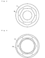
- each clutch disc 12 sliding contact with the clutch plate 11 is formed with grooves 12a radially outwardly extending toward the outer periphery of the clutch disc 12.
- These grooves 12a can guide and discharge oil present between sliding surfaces of the clutch discs 12 and the clutch plates 11.
- Reference numerals 14, 15 and 16 denote bearings (ball bearings) for rotatably supporting the input member 2 or the output member 3 relative to the case 1.
- reference numerals 17 and 18 denote oil seals to hold oil having predetermined viscosity within the case 1. Accordingly, the power transmitting apparatus 26 is a wet type.
- the solenoid 4 when the solenoid 4 is in an energized condition (i.e. condition of "ON"), the magnetic flux generated by the solenoid 4 acts on the armature 8 through the rotor 5 and thus the armature 8 is attracted and connected onto the rotor 5 against the urging force of the return spring 13. More particularly, while the armature 8 is attracted onto the rotor 5 by the magnetic flux, the armature 8 is also progressively rotated toward a same direction as that of the rotor 5 and the balls 9 roll along their cam surfaces upward.
- the boosting mechanism begins to display its function. Accordingly, the rotational torque of the housing or the input member 2 is converted to the axial thrusting force acting on the main clutch.
- the clutch plates 11 and clutch discs 12 are strongly pressed against each other by the boosting mechanism and therefore the input member or housing 2 and the output member or the shaft 3 are connected via the clutch hub 19. As the result of which, the rotational torque of the input member 2 is transmitted to the output member 3 and thus the output member 3 is rotated together with the input member 2.
- connection between the armature 8 and the rotor 5 is enormously increased. That is, according to the power transmitting apparatus of the present invention, since it is constituted so that the reaction force of the thrusting force converted by the boosting mechanism acts as the fastening force of the electromagnetic clutch (i.e. pressing force of the armature 8 against the rotor 5), it is possible to reduce the amount of electric current to be supplied to the solenoid 4 once the connection of the electromagnetic clutch has been achieved as well as possible to transmit a large torque due to the strong fastening force of the electromagnetic clutch.
- the fastening force of the electromagnetic clutch can be remarkably increased by using the thrusting force (i.e. the reaction force of the thrusting force) generated by the boosting mechanism as the fastening force of the electromagnetic clutch. That is, since the higher the magnification of the boosting mechanism, the larger the fastening force applied to the electromagnetic clutch, it is possible to perfectly unite the rotation of the input member 2 and that of the output member 3.
- the thrusting force i.e. the reaction force of the thrusting force
- the armature 8 and boosting mechanism are arranged at the side of housing (or input member) 2, it is possible to cancel the fastening force generated by the boosting mechanism and its reaction force each other and thus to reduce the weight and size of the power transmitting apparatus 26 without so much increasing the rigidity of the case 1. Furthermore, since the armature 8 has a portion of function of the boosting mechanism, it is possible to simplify the structure of the power transmitting apparatus 26 and thus to reduce its size.
- the reaction force of the thrusting force converted by the boosting mechanism can be utilized as the fastening force of the electromagnetic clutch, it is possible to transmit a large torque with small amount of current supplied to the electromagnet.
- the armature has a portion of function of the boosting mechanism, it is possible to simplify the structure of the power transmitting apparatus and thus to reduce its size.
- the boosting mechanism of the power transmitting apparatus can be formed by a conventional cam mechanism, it is possible to reduce the manufacturing cost of the power transmitting apparatus.
- the return spring since the return spring has an urging force such that it is sufficiently large so as to overcome the thrusting force generated at the boosting mechanism by a dragging torque caused by the return spring during the electromagnet is not energized but it is sufficiently small so as to be defeated by the attractive force for attracting the armature onto the rotor during the electromagnet is energized, it is possible to keep the clearance between the armature and the rotor during the solenoid is not energized and to securely attract and fasten the armature and the rotor each other.
- the rotor, the armature and the boosting mechanism are mounted on the side of the input member rotatably therewith, it is possible to cancel the fastening force generated by the boosting mechanism and its reaction force each other and thus to reduce the weight and size of the power transmitting apparatus without so much increasing the rigidity of the case.
- the main clutch is a multiple disc clutch, it is possible to set the rigidity and the strength of components lower values as compared to those of a conventional single disc clutch having a same transmission capacity.
- the present invention has been described with reference to the preferred embodiment, the present invention is not limited to such an illustrated embodiment and can be applied to any power transmission apparatus used to any apparatus other than a vehicle.
- the boosting mechanism is not limited to the illustrated ball cam type and can be constituted by any other form if it is able to convert a rotational torque of an input member (housing) to an axial thrusting force.
- the clutch disc 12 of the main clutch is formed with grooves 12a for discharging oil
- similar grooves can be formed on the surface of the rotor 5 with which the armature 8 slidably contacts.
Landscapes
- Engineering & Computer Science (AREA)
- General Engineering & Computer Science (AREA)
- Physics & Mathematics (AREA)
- Electromagnetism (AREA)
- Mechanical Engineering (AREA)
- Mechanical Operated Clutches (AREA)
- Arrangement And Driving Of Transmission Devices (AREA)
Applications Claiming Priority (2)
| Application Number | Priority Date | Filing Date | Title |
|---|---|---|---|
| JP2003203070A JP2005048788A (ja) | 2003-07-29 | 2003-07-29 | 動力伝達装置 |
| JP2003203070 | 2003-07-29 |
Publications (2)
| Publication Number | Publication Date |
|---|---|
| EP1503100A1 true EP1503100A1 (fr) | 2005-02-02 |
| EP1503100B1 EP1503100B1 (fr) | 2010-09-08 |
Family
ID=33535595
Family Applications (1)
| Application Number | Title | Priority Date | Filing Date |
|---|---|---|---|
| EP04017573A Expired - Lifetime EP1503100B1 (fr) | 2003-07-29 | 2004-07-24 | Dispositif de transmission de puissance avec embrayage à commande éléctromagnétique. |
Country Status (4)
| Country | Link |
|---|---|
| US (1) | US7083031B2 (fr) |
| EP (1) | EP1503100B1 (fr) |
| JP (1) | JP2005048788A (fr) |
| DE (1) | DE602004028994D1 (fr) |
Cited By (2)
| Publication number | Priority date | Publication date | Assignee | Title |
|---|---|---|---|---|
| DE102010045721A1 (de) * | 2010-09-16 | 2012-03-22 | Magna Powertrain Ag & Co. Kg | Drehmomentübertragungseinrichtung |
| CN102852996A (zh) * | 2011-06-28 | 2013-01-02 | 丰田自动车株式会社 | 电磁接合装置 |
Families Citing this family (5)
| Publication number | Priority date | Publication date | Assignee | Title |
|---|---|---|---|---|
| JP2006349109A (ja) * | 2005-06-17 | 2006-12-28 | Ntn Corp | 回転伝達装置 |
| JP2007315583A (ja) * | 2006-01-31 | 2007-12-06 | Gkn ドライブライン トルクテクノロジー株式会社 | クラッチ装置及びこれを用いたデファレンシャル装置 |
| JP4914463B2 (ja) * | 2009-05-20 | 2012-04-11 | 株式会社沖データ | 駆動伝達装置および画像形成装置 |
| US8276724B2 (en) * | 2009-08-26 | 2012-10-02 | Dymos Inc. | Power transmission system for vehicle changing power transmission state by electric control |
| US9221336B1 (en) * | 2011-11-14 | 2015-12-29 | Hydro-Gear Limited Partnership | Integral power distribution assembly for engine |
Citations (6)
| Publication number | Priority date | Publication date | Assignee | Title |
|---|---|---|---|---|
| CH315800A (de) * | 1953-02-18 | 1956-08-31 | Berner Charles | Elektromagnetisch betätigte Mehrscheiben-Reibungskupplung mit Selbst-Servowirkung |
| US2907426A (en) | 1955-03-23 | 1959-10-06 | Gen Motors Corp | Coupling for transmitting torques |
| JP2820161B2 (ja) | 1989-07-20 | 1998-11-05 | 栃木富士産業株式会社 | 連結装置 |
| EP1221393A1 (fr) | 2000-12-27 | 2002-07-10 | Tochigi Fuji Sangyo Kabushiki Kaisha | Construction et procédé pour supporter un embrayage électromagnetique |
| US20030018347A1 (en) | 2001-07-23 | 2003-01-23 | Ioannis Pallikaris | Device for separating the epithelium layer from the surface of the cornea of an eye |
| US20030183471A1 (en) * | 2002-03-27 | 2003-10-02 | Eaton Corporation | Dual mass clutch system |
Family Cites Families (4)
| Publication number | Priority date | Publication date | Assignee | Title |
|---|---|---|---|---|
| JP3361537B2 (ja) * | 1991-09-04 | 2003-01-07 | 栃木富士産業株式会社 | 電磁クラッチ |
| US5953959A (en) * | 1998-03-31 | 1999-09-21 | Eaton Corporation | Transmission inertia brake with ball ramp actuation |
| AT4491U1 (de) * | 2000-01-26 | 2001-07-25 | Steyr Daimler Puch Ag | Nasslaufende mehrscheibenkupplung für einen fahrzeug-antriebsstrang, insbesondere für eine differenzdrehzahlfühlende kupplung |
| US6481548B2 (en) * | 2000-08-08 | 2002-11-19 | Ntn Corporation | Two-way clutch with limited slip feature |
-
2003
- 2003-07-29 JP JP2003203070A patent/JP2005048788A/ja active Pending
-
2004
- 2004-07-24 EP EP04017573A patent/EP1503100B1/fr not_active Expired - Lifetime
- 2004-07-24 DE DE602004028994T patent/DE602004028994D1/de not_active Expired - Lifetime
- 2004-07-28 US US10/901,499 patent/US7083031B2/en not_active Expired - Fee Related
Patent Citations (6)
| Publication number | Priority date | Publication date | Assignee | Title |
|---|---|---|---|---|
| CH315800A (de) * | 1953-02-18 | 1956-08-31 | Berner Charles | Elektromagnetisch betätigte Mehrscheiben-Reibungskupplung mit Selbst-Servowirkung |
| US2907426A (en) | 1955-03-23 | 1959-10-06 | Gen Motors Corp | Coupling for transmitting torques |
| JP2820161B2 (ja) | 1989-07-20 | 1998-11-05 | 栃木富士産業株式会社 | 連結装置 |
| EP1221393A1 (fr) | 2000-12-27 | 2002-07-10 | Tochigi Fuji Sangyo Kabushiki Kaisha | Construction et procédé pour supporter un embrayage électromagnetique |
| US20030018347A1 (en) | 2001-07-23 | 2003-01-23 | Ioannis Pallikaris | Device for separating the epithelium layer from the surface of the cornea of an eye |
| US20030183471A1 (en) * | 2002-03-27 | 2003-10-02 | Eaton Corporation | Dual mass clutch system |
Cited By (3)
| Publication number | Priority date | Publication date | Assignee | Title |
|---|---|---|---|---|
| DE102010045721A1 (de) * | 2010-09-16 | 2012-03-22 | Magna Powertrain Ag & Co. Kg | Drehmomentübertragungseinrichtung |
| CN102852996A (zh) * | 2011-06-28 | 2013-01-02 | 丰田自动车株式会社 | 电磁接合装置 |
| CN102852996B (zh) * | 2011-06-28 | 2015-10-21 | 丰田自动车株式会社 | 电磁接合装置 |
Also Published As
| Publication number | Publication date |
|---|---|
| EP1503100B1 (fr) | 2010-09-08 |
| US20050023099A1 (en) | 2005-02-03 |
| US7083031B2 (en) | 2006-08-01 |
| JP2005048788A (ja) | 2005-02-24 |
| DE602004028994D1 (de) | 2010-10-21 |
Similar Documents
| Publication | Publication Date | Title |
|---|---|---|
| JP3628983B2 (ja) | 電磁クラッチを有した動力伝達装置 | |
| JP3658712B2 (ja) | ボールランプ機構及びこれを用いた駆動系クラッチ | |
| US7247118B2 (en) | Limited slip differential device | |
| JP4173367B2 (ja) | 自動車用四輪駆動トランスファ | |
| US5398792A (en) | Clutch device | |
| JPH10184731A (ja) | ボールランプアクチュエータ | |
| JPH11173350A (ja) | ボールランプアクチュエータ | |
| CN110177956A (zh) | 离合器组件及驱动组件 | |
| EP1503100B1 (fr) | Dispositif de transmission de puissance avec embrayage à commande éléctromagnétique. | |
| JP2000310260A (ja) | 複合クラッチ装置 | |
| CN102138020B (zh) | 离合器致动 | |
| JP3628982B2 (ja) | 電磁クラッチの潤滑構造 | |
| JP2004514848A (ja) | 駆動トルクの伝達のための装置 | |
| JP2003039968A (ja) | 動力伝達装置 | |
| JP2001082512A (ja) | クラッチ装置 | |
| JP2006189149A (ja) | デファレンシャル装置 | |
| JP2002195324A (ja) | 電磁クラッチ・ブレーキ装置 | |
| JP3815964B2 (ja) | カップリング装置 | |
| JP2006349109A (ja) | 回転伝達装置 | |
| JP2010006263A (ja) | 動力伝達装置及びこの動力伝達装置を用いた四輪駆動車 | |
| JP2003039969A (ja) | 動力伝達装置 | |
| JP2004060698A (ja) | 電磁ブレーキ | |
| JP2006349108A (ja) | 回転伝達装置 | |
| JP2005030443A (ja) | 回転伝達装置 | |
| JP3815965B2 (ja) | カップリング装置 |
Legal Events
| Date | Code | Title | Description |
|---|---|---|---|
| PUAI | Public reference made under article 153(3) epc to a published international application that has entered the european phase |
Free format text: ORIGINAL CODE: 0009012 |
|
| 17P | Request for examination filed |
Effective date: 20041117 |
|
| AK | Designated contracting states |
Kind code of ref document: A1 Designated state(s): AT BE BG CH CY CZ DE DK EE ES FI FR GB GR HU IE IT LI LU MC NL PL PT RO SE SI SK TR |
|
| AX | Request for extension of the european patent |
Extension state: AL HR LT LV MK |
|
| AKX | Designation fees paid |
Designated state(s): DE FR GB |
|
| 17Q | First examination report despatched |
Effective date: 20070227 |
|
| GRAP | Despatch of communication of intention to grant a patent |
Free format text: ORIGINAL CODE: EPIDOSNIGR1 |
|
| RIN1 | Information on inventor provided before grant (corrected) |
Inventor name: OOISHI, AKIOC/O KABUSHIKI KAISHA F.C.C. Inventor name: YOSHIMOTO, KATSUC/O KABUSHIKI KAISHA F.C.C. Inventor name: SAKURAI, YOSHIMIC/O KABUSHIKI KAISHA F.C.C. Inventor name: MIWA, NAOYUKIC/O KABUSHIKI KAISHA F.C.C. |
|
| GRAS | Grant fee paid |
Free format text: ORIGINAL CODE: EPIDOSNIGR3 |
|
| GRAA | (expected) grant |
Free format text: ORIGINAL CODE: 0009210 |
|
| AK | Designated contracting states |
Kind code of ref document: B1 Designated state(s): DE FR GB |
|
| REG | Reference to a national code |
Ref country code: GB Ref legal event code: FG4D |
|
| REF | Corresponds to: |
Ref document number: 602004028994 Country of ref document: DE Date of ref document: 20101021 Kind code of ref document: P |
|
| PLBE | No opposition filed within time limit |
Free format text: ORIGINAL CODE: 0009261 |
|
| STAA | Information on the status of an ep patent application or granted ep patent |
Free format text: STATUS: NO OPPOSITION FILED WITHIN TIME LIMIT |
|
| 26N | No opposition filed |
Effective date: 20110609 |
|
| REG | Reference to a national code |
Ref country code: DE Ref legal event code: R097 Ref document number: 602004028994 Country of ref document: DE Effective date: 20110609 |
|
| GBPC | Gb: european patent ceased through non-payment of renewal fee |
Effective date: 20110724 |
|
| PG25 | Lapsed in a contracting state [announced via postgrant information from national office to epo] |
Ref country code: GB Free format text: LAPSE BECAUSE OF NON-PAYMENT OF DUE FEES Effective date: 20110724 |
|
| REG | Reference to a national code |
Ref country code: FR Ref legal event code: PLFP Year of fee payment: 13 |
|
| PGFP | Annual fee paid to national office [announced via postgrant information from national office to epo] |
Ref country code: DE Payment date: 20160722 Year of fee payment: 13 |
|
| PGFP | Annual fee paid to national office [announced via postgrant information from national office to epo] |
Ref country code: FR Payment date: 20160721 Year of fee payment: 13 |
|
| REG | Reference to a national code |
Ref country code: DE Ref legal event code: R119 Ref document number: 602004028994 Country of ref document: DE |
|
| REG | Reference to a national code |
Ref country code: FR Ref legal event code: ST Effective date: 20180330 |
|
| PG25 | Lapsed in a contracting state [announced via postgrant information from national office to epo] |
Ref country code: DE Free format text: LAPSE BECAUSE OF NON-PAYMENT OF DUE FEES Effective date: 20180201 |
|
| PG25 | Lapsed in a contracting state [announced via postgrant information from national office to epo] |
Ref country code: FR Free format text: LAPSE BECAUSE OF NON-PAYMENT OF DUE FEES Effective date: 20170731 |