EP1503130A2 - Druckdichte Kupplungsvorrichtung mit thermischer Entkopplung - Google Patents
Druckdichte Kupplungsvorrichtung mit thermischer Entkopplung Download PDFInfo
- Publication number
- EP1503130A2 EP1503130A2 EP04103664A EP04103664A EP1503130A2 EP 1503130 A2 EP1503130 A2 EP 1503130A2 EP 04103664 A EP04103664 A EP 04103664A EP 04103664 A EP04103664 A EP 04103664A EP 1503130 A2 EP1503130 A2 EP 1503130A2
- Authority
- EP
- European Patent Office
- Prior art keywords
- end portion
- seal
- head
- conduit
- coupling device
- Prior art date
- Legal status (The legal status is an assumption and is not a legal conclusion. Google has not performed a legal analysis and makes no representation as to the accuracy of the status listed.)
- Granted
Links
Images


Classifications
-
- F—MECHANICAL ENGINEERING; LIGHTING; HEATING; WEAPONS; BLASTING
- F16—ENGINEERING ELEMENTS AND UNITS; GENERAL MEASURES FOR PRODUCING AND MAINTAINING EFFECTIVE FUNCTIONING OF MACHINES OR INSTALLATIONS; THERMAL INSULATION IN GENERAL
- F16L—PIPES; JOINTS OR FITTINGS FOR PIPES; SUPPORTS FOR PIPES, CABLES OR PROTECTIVE TUBING; MEANS FOR THERMAL INSULATION IN GENERAL
- F16L21/00—Joints with sleeve or socket
- F16L21/02—Joints with sleeve or socket with elastic sealing rings between pipe and sleeve or between pipe and socket, e.g. with rolling or other prefabricated profiled rings
-
- F—MECHANICAL ENGINEERING; LIGHTING; HEATING; WEAPONS; BLASTING
- F16—ENGINEERING ELEMENTS AND UNITS; GENERAL MEASURES FOR PRODUCING AND MAINTAINING EFFECTIVE FUNCTIONING OF MACHINES OR INSTALLATIONS; THERMAL INSULATION IN GENERAL
- F16L—PIPES; JOINTS OR FITTINGS FOR PIPES; SUPPORTS FOR PIPES, CABLES OR PROTECTIVE TUBING; MEANS FOR THERMAL INSULATION IN GENERAL
- F16L21/00—Joints with sleeve or socket
- F16L21/06—Joints with sleeve or socket with a divided sleeve or ring clamping around the pipe ends
Definitions
- the present invention relates to the field of tight couplings and connections between conduits, in particular in an environment of high temperatures and vibrations, ensuring the preservation of the seal. It relates to a tight coupling device with thermal decoupling of a conduit to a head.
- Such is particularly the case when connecting a feed conduit made of a thermoplastic material to a turbocharger of a supercharging system for an engine.
- This moulded piece/seal unit is press-fitted on the feed head of the turbocharger, the fitted assembly then being locked by a clamping screw.
- the object of the present invention is to overcome the drawbacks of this known solution and provide a new solution avoiding the need to use a particular moulded connection piece and allowing easier assembly, in particular with a limited force for assembly by fitting.
- the present invention relates to a device for coupling or connecting, with thermal decoupling, a circular section conduit, in particular made of a thermoplastic material, to a head of appropriate form, in particular made of a metallic material, by partially fitting an said end portion to lock said connection, characterised in that said end portion has an at least slightly flexible constitution, with preferably a flexible deformation capacity distributed uniformly over the circumference of said end portion, in that the clamp collar comprises an elastic compression reserve, and in that a seal with a tubular structure made of a fluorocarbon elastomer, for example FPM is placed between said sealing portion of the conduit and the head, being arranged in a substantially centred manner in relation to said clamp collar, and being applied to the head at the time of the clamping of the end portion.
- a device for coupling or connecting, with thermal decoupling, a circular section conduit, in particular made of a thermoplastic material, to a head of appropriate form, in particular made of a metallic material, by partially fitting an said end portion to lock said connection characterised
- Figure 1 of the accompanying drawings shows a device for coupling or connecting, with thermal decoupling, a circular section conduit 1, in particular made of a thermoplastic material, to a head 2 of appropriate form, in particular made of a metallic material, by partially fitting an end portion 3 of said conduit 1 onto said head 2, a clamp collar 4 being placed on the external face of said end portion 3 to lock said connection.
- said end portion 3 has an at least slightly flexible constitution, with preferably a flexible deformation capacity distributed uniformly over the circumference of said end portion 3.
- the clamp collar 4 comprises an elastic compression reserve 4' and a seal 5 with a tubular structure made of a fluorocarbon elastomer of the type known as FPM is placed between said seal portion 3 of the conduit and the head 2, being arranged in a substantially centred manner in relation to said clamp collar 4 and being applied to the head 2 at the time of the clamping of the end portion 3.
- end portion 3 By making the end portion 3 from a flexible material, preferably the same material as that of which the rest of the conduit 1 is made (1 and 3 forming a single piece), for example PEEST (or HYTREL, registered name), deformation may be distributed uniformly, facilitating in particular, in cooperation with the clamp 4 for elastic reserve 4', correction of dimensional variations caused by variations in temperature.
- PEEST or HYTREL, registered name
- the conduit 1 with its end portion 3 is made as a single piece, for example by injection moulding/blowing, and the particular qualities of the material from which the seal 5 is made give this seal a high thermal decoupling capacity, said decoupling applying to all of the part of the end portion 3 in immediate proximity to the head 2 by virtue of the tubular shape of the body 5' of said seal 5.
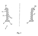
- the wall of the end portion 3 may advantageously comprise two circumferential deformations 6, which may or may not be continuous, located in two mutually parallel planes perpendicular to the longitudinal central axis of said portion 3. These deformations form ribs 7 on the exterior face of said portion and grooves or slots 8 on its inner face, and the seal 5 comprises two exterior peripheral ribs 9 intended to be accommodated respectively in said grooves or slots 8 when said seal 5 is fitted in said end portion 3.
- One of said slots 8 may be formed, for example, by a recessed wall zone of the conduit 1 between its tubular body and its end portion 3.
- said seal 5 may comprise in the region of its longitudinal edge, located after assembly in the region of the orifice 3' of the end portion 3 of the conduit 1, an exterior circumferential lip 10 inclined in the direction of the longitudinal edge opposite said seal 5.
- This lip 10 is hook-shaped in section and grips intimately onto the free edge of the conduit 1 in order to ensure that the tubular seal 4 is fastened to this conduit.
- the tubular body 5' of the seal 5 may comprise on its interior face a plurality of parallel circumferential circular ribs 11, spaced out from one another in the longitudinal direction of said body 5'.
- the exterior face of the head 2 may optionally comprise grooves to receive said ribs 11.
- the wall of the end portion 3 comprises ribs 3" on its internal face, obtained, for example, by deformation of said wall and located, if necessary, opposite the internal ribs 11 of the tubular seal 5.
- the tubular body 5' of the seal 5 comprises in the region of its longitudinal edge, located after assembly at a distance from the orifice 3' of the end portion 3 of the conduit 1, an internal circular radial rib 12 intended to form a stop (in the longitudinal direction) for the head 2 inserted in said end portion 3 of the conduit 1.
- the radially protruding shape of the rib 12 allows it to cover the free edge of the head 2 and therefore, in conjunction with the particular properties of the material (FPM) from which the tubular seal 5 is made, causes a thermal decoupling against the thermal radiation emitted by said head 2.
- the elastic compression reserve 4' consists of a segment of an undulating leaf spring installed between the clamp band of the collar 4 and a leaf or plate part forming a support base fastened at its two ends to said band.
- the clamp collar 4 used may, for example, be of the type sold by the company NORMA.
- the present invention also relates to a supercharging system for an internal combustion engine comprising, in particular, a turbocharger comprising an air intake or an air-and-petrol mixture intake head and an air or an air-and-petrol mixture feed conduit, connected to said head in the region of an outflow end portion, characterised in that the coupling or connection of the conduit 1 to the head 2 is realised via a coupling device as described above.
- a turbocharger comprising an air intake or an air-and-petrol mixture intake head and an air or an air-and-petrol mixture feed conduit, connected to said head in the region of an outflow end portion, characterised in that the coupling or connection of the conduit 1 to the head 2 is realised via a coupling device as described above.
Landscapes
- Engineering & Computer Science (AREA)
- General Engineering & Computer Science (AREA)
- Mechanical Engineering (AREA)
- Quick-Acting Or Multi-Walled Pipe Joints (AREA)
- Lining Or Joining Of Plastics Or The Like (AREA)
- Flanged Joints, Insulating Joints, And Other Joints (AREA)
- Packages (AREA)
- Coupling Device And Connection With Printed Circuit (AREA)
- External Artificial Organs (AREA)
- Gasket Seals (AREA)
Applications Claiming Priority (2)
| Application Number | Priority Date | Filing Date | Title |
|---|---|---|---|
| FR0309349 | 2003-07-29 | ||
| FR0309349A FR2858388B1 (fr) | 2003-07-29 | 2003-07-29 | Dispositif de raccordement etanche avec decouplage thermique |
Publications (3)
| Publication Number | Publication Date |
|---|---|
| EP1503130A2 true EP1503130A2 (de) | 2005-02-02 |
| EP1503130A3 EP1503130A3 (de) | 2006-01-18 |
| EP1503130B1 EP1503130B1 (de) | 2009-10-07 |
Family
ID=33523016
Family Applications (1)
| Application Number | Title | Priority Date | Filing Date |
|---|---|---|---|
| EP04103664A Expired - Lifetime EP1503130B1 (de) | 2003-07-29 | 2004-07-29 | Druckdichte Kupplungsvorrichtung mit thermischer Entkopplung |
Country Status (4)
| Country | Link |
|---|---|
| EP (1) | EP1503130B1 (de) |
| AT (1) | ATE445119T1 (de) |
| DE (1) | DE602004023458D1 (de) |
| FR (1) | FR2858388B1 (de) |
Family Cites Families (3)
| Publication number | Priority date | Publication date | Assignee | Title |
|---|---|---|---|---|
| US5137308A (en) * | 1988-04-27 | 1992-08-11 | Donaldson Company, Inc. | Air transfer system |
| DE19833302A1 (de) * | 1998-07-24 | 2000-01-27 | Wahler Gmbh & Co Gustav | Leitungsverbindung bei einer Einrichtung zur Abgasrückführung |
| JP3925775B2 (ja) * | 2001-09-07 | 2007-06-06 | 豊田合成株式会社 | 樹脂チューブ |
-
2003
- 2003-07-29 FR FR0309349A patent/FR2858388B1/fr not_active Expired - Fee Related
-
2004
- 2004-07-29 EP EP04103664A patent/EP1503130B1/de not_active Expired - Lifetime
- 2004-07-29 AT AT04103664T patent/ATE445119T1/de not_active IP Right Cessation
- 2004-07-29 DE DE602004023458T patent/DE602004023458D1/de not_active Expired - Lifetime
Also Published As
| Publication number | Publication date |
|---|---|
| FR2858388B1 (fr) | 2005-10-14 |
| DE602004023458D1 (de) | 2009-11-19 |
| EP1503130B1 (de) | 2009-10-07 |
| FR2858388A1 (fr) | 2005-02-04 |
| ATE445119T1 (de) | 2009-10-15 |
| EP1503130A3 (de) | 2006-01-18 |
Similar Documents
| Publication | Publication Date | Title |
|---|---|---|
| US7832775B2 (en) | Bayonet air guide connector for a turbocharger | |
| US10220555B2 (en) | Air duct cuff and method of manufacture | |
| CA2246469C (en) | Clean air ducts and methods for the manufacturing thereof | |
| CA2193575C (en) | Radiator support | |
| US7497478B2 (en) | Duct assembly | |
| KR20000067893A (ko) | 연결파이프 상에 주름관을 부착하는 부착장치 | |
| US8267435B2 (en) | Charge-air hose assembly | |
| US4903644A (en) | Air intake section of an internal combustion engine | |
| CN104603445A (zh) | 用于将管形的构件固定在附加安装结构上的保持件 | |
| US20210285579A1 (en) | Duct connector | |
| JP2002526728A (ja) | ベローズ形カバー部材 | |
| US4727843A (en) | Mounting retainer for electromagnetic fuel injector | |
| CN214662856U (zh) | 柔性接头 | |
| US6209885B1 (en) | Boot for universal joint | |
| US11015741B2 (en) | Adjustable fastening support for mounting a tubular item on an outer member | |
| EP1503130B1 (de) | Druckdichte Kupplungsvorrichtung mit thermischer Entkopplung | |
| US8677966B2 (en) | Air intake flow device and system | |
| US6588389B1 (en) | Shift drum | |
| US8740713B2 (en) | Folding bellows arrangement for a tripod joint unit | |
| US12281743B2 (en) | Insulated subassembly | |
| US20080169649A1 (en) | Flange coupling of two pipes, in particular the pipes of an exhaust system of a motor vehicle internal combustion engine | |
| JPH07259996A (ja) | 保護ベローズ | |
| CN211287895U (zh) | 护套结构及发动机管件连接结构 | |
| KR101357472B1 (ko) | 자동차용 인터쿨러와 플라스틱 덕트 결합구조 | |
| EP3430303B1 (de) | Verbindersystem mit einem verbinderanschlussstück für einen flüssigkeitsschlauch in einem fahrzeug |
Legal Events
| Date | Code | Title | Description |
|---|---|---|---|
| PUAI | Public reference made under article 153(3) epc to a published international application that has entered the european phase |
Free format text: ORIGINAL CODE: 0009012 |
|
| AK | Designated contracting states |
Kind code of ref document: A2 Designated state(s): AT BE BG CH CY CZ DE DK EE ES FI FR GB GR HU IE IT LI LU MC NL PL PT RO SE SI SK TR |
|
| AX | Request for extension of the european patent |
Extension state: AL HR LT LV MK |
|
| PUAL | Search report despatched |
Free format text: ORIGINAL CODE: 0009013 |
|
| AK | Designated contracting states |
Kind code of ref document: A3 Designated state(s): AT BE BG CH CY CZ DE DK EE ES FI FR GB GR HU IE IT LI LU MC NL PL PT RO SE SI SK TR |
|
| AX | Request for extension of the european patent |
Extension state: AL HR LT LV MK |
|
| 17P | Request for examination filed |
Effective date: 20060714 |
|
| AKX | Designation fees paid |
Designated state(s): AT BE BG CH CY CZ DE DK EE ES FI FR GB GR HU IE IT LI LU MC NL PL PT RO SE SI SK TR |
|
| GRAP | Despatch of communication of intention to grant a patent |
Free format text: ORIGINAL CODE: EPIDOSNIGR1 |
|
| GRAS | Grant fee paid |
Free format text: ORIGINAL CODE: EPIDOSNIGR3 |
|
| GRAA | (expected) grant |
Free format text: ORIGINAL CODE: 0009210 |
|
| AK | Designated contracting states |
Kind code of ref document: B1 Designated state(s): AT BE BG CH CY CZ DE DK EE ES FI FR GB GR HU IE IT LI LU MC NL PL PT RO SE SI SK TR |
|
| REG | Reference to a national code |
Ref country code: GB Ref legal event code: FG4D |
|
| REG | Reference to a national code |
Ref country code: CH Ref legal event code: EP |
|
| REG | Reference to a national code |
Ref country code: IE Ref legal event code: FG4D |
|
| REF | Corresponds to: |
Ref document number: 602004023458 Country of ref document: DE Date of ref document: 20091119 Kind code of ref document: P |
|
| PG25 | Lapsed in a contracting state [announced via postgrant information from national office to epo] |
Ref country code: SI Free format text: LAPSE BECAUSE OF FAILURE TO SUBMIT A TRANSLATION OF THE DESCRIPTION OR TO PAY THE FEE WITHIN THE PRESCRIBED TIME-LIMIT Effective date: 20091007 |
|
| NLV1 | Nl: lapsed or annulled due to failure to fulfill the requirements of art. 29p and 29m of the patents act | ||
| REG | Reference to a national code |
Ref country code: FR Ref legal event code: CA Ref country code: FR Ref legal event code: CJ |
|
| PG25 | Lapsed in a contracting state [announced via postgrant information from national office to epo] |
Ref country code: FI Free format text: LAPSE BECAUSE OF FAILURE TO SUBMIT A TRANSLATION OF THE DESCRIPTION OR TO PAY THE FEE WITHIN THE PRESCRIBED TIME-LIMIT Effective date: 20091007 Ref country code: PT Free format text: LAPSE BECAUSE OF FAILURE TO SUBMIT A TRANSLATION OF THE DESCRIPTION OR TO PAY THE FEE WITHIN THE PRESCRIBED TIME-LIMIT Effective date: 20100208 Ref country code: ES Free format text: LAPSE BECAUSE OF FAILURE TO SUBMIT A TRANSLATION OF THE DESCRIPTION OR TO PAY THE FEE WITHIN THE PRESCRIBED TIME-LIMIT Effective date: 20100118 Ref country code: SE Free format text: LAPSE BECAUSE OF FAILURE TO SUBMIT A TRANSLATION OF THE DESCRIPTION OR TO PAY THE FEE WITHIN THE PRESCRIBED TIME-LIMIT Effective date: 20091007 |
|
| PG25 | Lapsed in a contracting state [announced via postgrant information from national office to epo] |
Ref country code: PL Free format text: LAPSE BECAUSE OF FAILURE TO SUBMIT A TRANSLATION OF THE DESCRIPTION OR TO PAY THE FEE WITHIN THE PRESCRIBED TIME-LIMIT Effective date: 20091007 |
|
| PG25 | Lapsed in a contracting state [announced via postgrant information from national office to epo] |
Ref country code: BE Free format text: LAPSE BECAUSE OF FAILURE TO SUBMIT A TRANSLATION OF THE DESCRIPTION OR TO PAY THE FEE WITHIN THE PRESCRIBED TIME-LIMIT Effective date: 20091007 Ref country code: AT Free format text: LAPSE BECAUSE OF FAILURE TO SUBMIT A TRANSLATION OF THE DESCRIPTION OR TO PAY THE FEE WITHIN THE PRESCRIBED TIME-LIMIT Effective date: 20091007 |
|
| PG25 | Lapsed in a contracting state [announced via postgrant information from national office to epo] |
Ref country code: DK Free format text: LAPSE BECAUSE OF FAILURE TO SUBMIT A TRANSLATION OF THE DESCRIPTION OR TO PAY THE FEE WITHIN THE PRESCRIBED TIME-LIMIT Effective date: 20091007 Ref country code: EE Free format text: LAPSE BECAUSE OF FAILURE TO SUBMIT A TRANSLATION OF THE DESCRIPTION OR TO PAY THE FEE WITHIN THE PRESCRIBED TIME-LIMIT Effective date: 20091007 Ref country code: BG Free format text: LAPSE BECAUSE OF FAILURE TO SUBMIT A TRANSLATION OF THE DESCRIPTION OR TO PAY THE FEE WITHIN THE PRESCRIBED TIME-LIMIT Effective date: 20100107 Ref country code: NL Free format text: LAPSE BECAUSE OF FAILURE TO SUBMIT A TRANSLATION OF THE DESCRIPTION OR TO PAY THE FEE WITHIN THE PRESCRIBED TIME-LIMIT Effective date: 20091007 Ref country code: RO Free format text: LAPSE BECAUSE OF FAILURE TO SUBMIT A TRANSLATION OF THE DESCRIPTION OR TO PAY THE FEE WITHIN THE PRESCRIBED TIME-LIMIT Effective date: 20091007 |
|
| PLBE | No opposition filed within time limit |
Free format text: ORIGINAL CODE: 0009261 |
|
| STAA | Information on the status of an ep patent application or granted ep patent |
Free format text: STATUS: NO OPPOSITION FILED WITHIN TIME LIMIT |
|
| PG25 | Lapsed in a contracting state [announced via postgrant information from national office to epo] |
Ref country code: SK Free format text: LAPSE BECAUSE OF FAILURE TO SUBMIT A TRANSLATION OF THE DESCRIPTION OR TO PAY THE FEE WITHIN THE PRESCRIBED TIME-LIMIT Effective date: 20091007 Ref country code: CZ Free format text: LAPSE BECAUSE OF FAILURE TO SUBMIT A TRANSLATION OF THE DESCRIPTION OR TO PAY THE FEE WITHIN THE PRESCRIBED TIME-LIMIT Effective date: 20091007 |
|
| 26N | No opposition filed |
Effective date: 20100708 |
|
| PG25 | Lapsed in a contracting state [announced via postgrant information from national office to epo] |
Ref country code: GR Free format text: LAPSE BECAUSE OF FAILURE TO SUBMIT A TRANSLATION OF THE DESCRIPTION OR TO PAY THE FEE WITHIN THE PRESCRIBED TIME-LIMIT Effective date: 20100108 |
|
| PG25 | Lapsed in a contracting state [announced via postgrant information from national office to epo] |
Ref country code: MC Free format text: LAPSE BECAUSE OF NON-PAYMENT OF DUE FEES Effective date: 20100731 |
|
| REG | Reference to a national code |
Ref country code: CH Ref legal event code: PL |
|
| GBPC | Gb: european patent ceased through non-payment of renewal fee |
Effective date: 20100729 |
|
| PG25 | Lapsed in a contracting state [announced via postgrant information from national office to epo] |
Ref country code: IT Free format text: LAPSE BECAUSE OF FAILURE TO SUBMIT A TRANSLATION OF THE DESCRIPTION OR TO PAY THE FEE WITHIN THE PRESCRIBED TIME-LIMIT Effective date: 20091007 |
|
| PG25 | Lapsed in a contracting state [announced via postgrant information from national office to epo] |
Ref country code: CH Free format text: LAPSE BECAUSE OF NON-PAYMENT OF DUE FEES Effective date: 20100731 Ref country code: LI Free format text: LAPSE BECAUSE OF NON-PAYMENT OF DUE FEES Effective date: 20100731 |
|
| PG25 | Lapsed in a contracting state [announced via postgrant information from national office to epo] |
Ref country code: IE Free format text: LAPSE BECAUSE OF NON-PAYMENT OF DUE FEES Effective date: 20100729 Ref country code: GB Free format text: LAPSE BECAUSE OF NON-PAYMENT OF DUE FEES Effective date: 20100729 |
|
| PG25 | Lapsed in a contracting state [announced via postgrant information from national office to epo] |
Ref country code: CY Free format text: LAPSE BECAUSE OF FAILURE TO SUBMIT A TRANSLATION OF THE DESCRIPTION OR TO PAY THE FEE WITHIN THE PRESCRIBED TIME-LIMIT Effective date: 20091007 |
|
| PG25 | Lapsed in a contracting state [announced via postgrant information from national office to epo] |
Ref country code: LU Free format text: LAPSE BECAUSE OF NON-PAYMENT OF DUE FEES Effective date: 20100729 Ref country code: HU Free format text: LAPSE BECAUSE OF FAILURE TO SUBMIT A TRANSLATION OF THE DESCRIPTION OR TO PAY THE FEE WITHIN THE PRESCRIBED TIME-LIMIT Effective date: 20100408 |
|
| PG25 | Lapsed in a contracting state [announced via postgrant information from national office to epo] |
Ref country code: TR Free format text: LAPSE BECAUSE OF FAILURE TO SUBMIT A TRANSLATION OF THE DESCRIPTION OR TO PAY THE FEE WITHIN THE PRESCRIBED TIME-LIMIT Effective date: 20091007 |
|
| PGFP | Annual fee paid to national office [announced via postgrant information from national office to epo] |
Ref country code: DE Payment date: 20120921 Year of fee payment: 9 |
|
| REG | Reference to a national code |
Ref country code: DE Ref legal event code: R119 Ref document number: 602004023458 Country of ref document: DE Effective date: 20140201 |
|
| PG25 | Lapsed in a contracting state [announced via postgrant information from national office to epo] |
Ref country code: DE Free format text: LAPSE BECAUSE OF NON-PAYMENT OF DUE FEES Effective date: 20140201 |
|
| REG | Reference to a national code |
Ref country code: FR Ref legal event code: PLFP Year of fee payment: 13 |
|
| REG | Reference to a national code |
Ref country code: FR Ref legal event code: PLFP Year of fee payment: 14 |
|
| REG | Reference to a national code |
Ref country code: FR Ref legal event code: PLFP Year of fee payment: 15 |
|
| PGFP | Annual fee paid to national office [announced via postgrant information from national office to epo] |
Ref country code: FR Payment date: 20230621 Year of fee payment: 20 |