EP1503136A2 - Lens für eine LED Signalleuchte - Google Patents
Lens für eine LED Signalleuchte Download PDFInfo
- Publication number
- EP1503136A2 EP1503136A2 EP04017822A EP04017822A EP1503136A2 EP 1503136 A2 EP1503136 A2 EP 1503136A2 EP 04017822 A EP04017822 A EP 04017822A EP 04017822 A EP04017822 A EP 04017822A EP 1503136 A2 EP1503136 A2 EP 1503136A2
- Authority
- EP
- European Patent Office
- Prior art keywords
- lens
- light
- horizontal
- degrees
- optical axis
- Prior art date
- Legal status (The legal status is an assumption and is not a legal conclusion. Google has not performed a legal analysis and makes no representation as to the accuracy of the status listed.)
- Withdrawn
Links
Images


Classifications
-
- F—MECHANICAL ENGINEERING; LIGHTING; HEATING; WEAPONS; BLASTING
- F21—LIGHTING
- F21V—FUNCTIONAL FEATURES OR DETAILS OF LIGHTING DEVICES OR SYSTEMS THEREOF; STRUCTURAL COMBINATIONS OF LIGHTING DEVICES WITH OTHER ARTICLES, NOT OTHERWISE PROVIDED FOR
- F21V5/00—Refractors for light sources
- F21V5/04—Refractors for light sources of lens shape
- F21V5/045—Refractors for light sources of lens shape the lens having discontinuous faces, e.g. Fresnel lenses
-
- F—MECHANICAL ENGINEERING; LIGHTING; HEATING; WEAPONS; BLASTING
- F21—LIGHTING
- F21S—NON-PORTABLE LIGHTING DEVICES; SYSTEMS THEREOF; VEHICLE LIGHTING DEVICES SPECIALLY ADAPTED FOR VEHICLE EXTERIORS
- F21S43/00—Signalling devices specially adapted for vehicle exteriors, e.g. brake lamps, direction indicator lights or reversing lights
- F21S43/10—Signalling devices specially adapted for vehicle exteriors, e.g. brake lamps, direction indicator lights or reversing lights characterised by the light source
- F21S43/13—Signalling devices specially adapted for vehicle exteriors, e.g. brake lamps, direction indicator lights or reversing lights characterised by the light source characterised by the type of light source
- F21S43/14—Light emitting diodes [LED]
-
- F—MECHANICAL ENGINEERING; LIGHTING; HEATING; WEAPONS; BLASTING
- F21—LIGHTING
- F21S—NON-PORTABLE LIGHTING DEVICES; SYSTEMS THEREOF; VEHICLE LIGHTING DEVICES SPECIALLY ADAPTED FOR VEHICLE EXTERIORS
- F21S43/00—Signalling devices specially adapted for vehicle exteriors, e.g. brake lamps, direction indicator lights or reversing lights
- F21S43/20—Signalling devices specially adapted for vehicle exteriors, e.g. brake lamps, direction indicator lights or reversing lights characterised by refractors, transparent cover plates, light guides or filters
- F21S43/26—Refractors, transparent cover plates, light guides or filters not provided in groups F21S43/235 - F21S43/255
Definitions
- This application relates to lenses and more particularly to lenses for automotive signal lamps. Still more particularly, it relates to lenses for signal lamps employing light emitting diodes as the light source.
- the LEDs are aligned so that the central axis of light from the LEDs is pointed at the center of the field to be illuminated and the lens is perpendicular to the axis orientation.
- a Fresnel refractor Formed on the side of the lens facing the LEDs is a Fresnel refractor and formed on the side of the lens facing the field to be illuminated is a series of pillow-type lens elements.
- the LED light is directed by the Fresnel element in both the horizontal and vertical directions into a collimated beam.
- the external pillow lens elements then direct the collimated beam into the required vertical and horizontal angular light distributions.
- the disadvantage of this design is that such a lens may not be perpendicular to the optical axis of the test pattern. This may be due to actual construction or because it is inconvenient to position the lens vertically in the preferred vehicle design. Typically the windows are sloped, thereby requiring a slopped lens face.
- the circular Fresnel lens collimates light along the axis of the lens tilt rather than the optical axis, which makes the system incapable of meeting light distribution.
- an additional inner lens piece with the Fresnel or the Fresnel and the pillows that was perpendicular to the optical axis was used. This inner lens increased the cost and reduced the amount of available light.
- CHMSLs Center high mount stop lamps
- LED CHMSLs have been made with lenses provided on the inside surface with one or more circular Fresnel lens area that would receive and collimate the light respectively fro a corresponding LED.
- the collimated light passed through the lens to the exterior surface where it encountered square, pillow type lens elements the spread the light vertically and horizontally.
- This lens had to be aligned so that the central, i.e., axial radiation from the LED went through the center of the corresponding Fresnel lens portion and was parallel to the normal axis of the lens. If the lens were positioned so that the LED axis was at an angle to the lens normal, for example, where a user wants the lens to have a different face angle to fit against a window, then the lens would direct light substantially along the axis of tilt. For an LED lamp system there may be too little light to start with so the misdirection amounted to an intolerable light loss from the obligated legal requirements.
- an automotive signal lamp comprising a housing having a cavity closed by a lens; a light source positioned within said cavity directed toward said lens; said lens having a first surface facing said light source and a second surface facing a field to be illuminated, said first surface being provided with a plurality of horizontal fresnel lenses and said second surface being provided with a plurality of horizontal pillow optics.
- this lens structure allows for the use of a single lens design for an LED that has the lens axis tilted at an angle other than 90 degrees with respect to the optical axis.
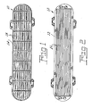
- Fig. 1 is an elevational view of the front side of a lens employing an embodiment of the invention
- Fig. 2 is an elevational view of the rear or lamp side of a lens employing an embodiment of the invention
- Fig. 3 is a diagrammatic view of the light distribution from a prior art lens
- Fig. 4 is a diagrammatic view of the light distribution from a lens of the invention taken in a vertical cross-section;
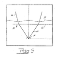
- Fig. 5 is a diagrammatic view of the light distribution from a lens of the invention in a horizontal cross-section; and.
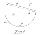
- Fig. 6 is a diagrammatic view of an automotive signal lamp.
- a lens 10 comprising a first surface 12 and a second surface 14.
- the first surface 12 is provided with a plurality of horizontal, linear Fresnel lenses 16 and the second surface 14 is provided with a plurality of horizontal pillow optics 18.
- the horizontal, linear fresnel lenses 16 of the first surface 12 provide vertical refraction of light from a central axis sufficient to collimate light from a point to within ⁇ 70 degrees of the optical axis and the pillow optics 18 of the second surface provide both vertical spread to ⁇ 12 degrees and horizontal spread of the light from a point to within ⁇ 70 degrees of the optical axis to ⁇ 25 degrees from the medial plane.
- the lens is employed with an automotive signal lamp 30.
- the lamp 30 comprises a housing 32 having a cavity 34 closed by the lens 10.
- a light source 36 such as a light emitting diode is positioned within the cavity and directed toward the lens 10.
- the lens has a first surface 12 facing the light source 36 and a second surface 14 facing a field to be illuminated.
- the first surface 12 is provided with the plurality of horizontal Fresnel lenses 16 and the second surface 14 is provided with the plurality of horizontal pillow optics 18.
- Fig. 3 displays a prior art lens 50 having pillow lenses 52 and circular Fresnel lenses 54.
- the light is directed by the Fresnel element in both the horizontal and vertical directions into a collimated beam 55.
- the external pillow lenses 52 are then used to direct the collimated beam into the required signal lamp distribution 57.
- the disadvantage of this design occurs if the lens is not perpendicular to the optical axis of the test pattern.
- the circular Fresnel lens will collimate light along the axis of the lens tilt rather than the optical axis, which will make the system incapable of meeting the required light distribution.
- the lens 10 can be set an angle of other than 90 ° as shown in the vertical cross-section in Fig. 4.
- the beam 60 from the light source 36 is collimated as at 62 by the linear Fresnel lenses 16 to a directed pattern 64.
- the effect of the linear fresnel lenses can be seen on the improved directed light pattern 66.
Landscapes
- Engineering & Computer Science (AREA)
- General Engineering & Computer Science (AREA)
- Physics & Mathematics (AREA)
- Microelectronics & Electronic Packaging (AREA)
- Optics & Photonics (AREA)
- Non-Portable Lighting Devices Or Systems Thereof (AREA)
Applications Claiming Priority (4)
| Application Number | Priority Date | Filing Date | Title |
|---|---|---|---|
| US879953 | 1997-06-20 | ||
| US49084803P | 2003-07-29 | 2003-07-29 | |
| US490848P | 2003-07-29 | ||
| US10/879,953 US7484871B2 (en) | 2003-07-29 | 2004-06-29 | Single lens for LED signal light |
Publications (2)
| Publication Number | Publication Date |
|---|---|
| EP1503136A2 true EP1503136A2 (de) | 2005-02-02 |
| EP1503136A3 EP1503136A3 (de) | 2007-08-01 |
Family
ID=33544747
Family Applications (1)
| Application Number | Title | Priority Date | Filing Date |
|---|---|---|---|
| EP04017822A Withdrawn EP1503136A3 (de) | 2003-07-29 | 2004-07-28 | Lens für eine LED Signalleuchte |
Country Status (5)
| Country | Link |
|---|---|
| US (1) | US7484871B2 (de) |
| EP (1) | EP1503136A3 (de) |
| JP (1) | JP2005049875A (de) |
| CN (1) | CN1590837A (de) |
| CA (1) | CA2472959C (de) |
Cited By (1)
| Publication number | Priority date | Publication date | Assignee | Title |
|---|---|---|---|---|
| EP2039982A1 (de) * | 2007-09-21 | 2009-03-25 | Shenzhen Gasun Energy Technology Co. Ltd. | LED-Beleuchtungsvorrichung für eine Straßenlaterne |
Families Citing this family (22)
| Publication number | Priority date | Publication date | Assignee | Title |
|---|---|---|---|---|
| WO2007081719A2 (en) | 2006-01-05 | 2007-07-19 | Illumitex, Inc. | Separate optical device for directing light from an led |
| US20090275157A1 (en) * | 2006-10-02 | 2009-11-05 | Illumitex, Inc. | Optical device shaping |
| US20090275266A1 (en) * | 2006-10-02 | 2009-11-05 | Illumitex, Inc. | Optical device polishing |
| US8087960B2 (en) * | 2006-10-02 | 2012-01-03 | Illumitex, Inc. | LED system and method |
| TW200918828A (en) * | 2007-10-31 | 2009-05-01 | Taiwan Network Comp & Amp Electronic Co Ltd | Light distribution lenticular sheet |
| JP2011512037A (ja) * | 2008-02-08 | 2011-04-14 | イルミテックス, インコーポレイテッド | エミッタ層成形のためのシステムおよび方法 |
| EP2180243B1 (de) * | 2008-10-16 | 2011-08-24 | Osram Gesellschaft mit beschränkter Haftung | Verfahren zur Auslegung optischer Systeme und entsprechendes optisches System |
| TW201034256A (en) * | 2008-12-11 | 2010-09-16 | Illumitex Inc | Systems and methods for packaging light-emitting diode devices |
| CN101684918A (zh) * | 2009-05-22 | 2010-03-31 | 西安智海电力科技有限公司 | Led光源的非成像光学定向配光透镜 |
| US8585253B2 (en) | 2009-08-20 | 2013-11-19 | Illumitex, Inc. | System and method for color mixing lens array |
| US8449128B2 (en) * | 2009-08-20 | 2013-05-28 | Illumitex, Inc. | System and method for a lens and phosphor layer |
| JP6006547B2 (ja) * | 2011-07-06 | 2016-10-12 | ミネベア株式会社 | 照明装置及びこれに用いるレンズシート |
| DE102012016545A1 (de) * | 2011-08-21 | 2013-02-21 | Jenoptik Polymer Systems Gmbh | LED-Leuchte |
| US9122000B2 (en) * | 2011-08-24 | 2015-09-01 | Minebea Co., Ltd. | Illuminator using a combination of pseudo-white LED and lens sheet |
| CN102679254B (zh) * | 2012-04-19 | 2014-03-12 | 重庆大学 | 大功率led近光灯光学系统 |
| JP6142463B2 (ja) * | 2013-02-22 | 2017-06-07 | スタンレー電気株式会社 | 車両用前照灯及び投影レンズ |
| US9546771B2 (en) | 2013-08-26 | 2017-01-17 | GE Lighting Solutions, LLC | Packed pillow optic array |
| US9736895B1 (en) | 2013-10-03 | 2017-08-15 | Ketra, Inc. | Color mixing optics for LED illumination device |
| CA3021728A1 (en) * | 2016-04-21 | 2017-10-26 | Hubbell Incorporated | Wall wash light fixture |
| US10364961B2 (en) | 2017-10-31 | 2019-07-30 | Rebo Lighting & Electronics, Llc | Illumination device for a vehicle |
| US11125407B1 (en) | 2020-03-10 | 2021-09-21 | Ford Global Technologies, Llc | Vehicle lamp assembly |
| DE102022129412A1 (de) * | 2021-12-03 | 2023-06-07 | Autosystems, A Division Of Magna Exteriors Inc. | Mini- oder mikro-led-basiertes lichtmodul, das so ausgebildet ist, dass es mehrere lichtfunktionen nahtlos mit verschiedenen lichtleitern in einer einheitlichen anordnung ausführen kann |
Family Cites Families (23)
| Publication number | Priority date | Publication date | Assignee | Title |
|---|---|---|---|---|
| US4722023A (en) * | 1984-05-15 | 1988-01-26 | Koito Seisakusho Co., Ltd. | Lamp assembly for emitting a beam of light at an angle to its optical axis |
| JPS6177832A (ja) * | 1984-09-25 | 1986-04-21 | Mitsubishi Electric Corp | 透過形スクリ−ン |
| FR2608733B1 (fr) * | 1986-12-23 | 1991-08-09 | Cibie Projecteurs | Feu de signalisation de faible profondeur pour vehicule automobile |
| US4868725A (en) * | 1988-10-31 | 1989-09-19 | Koito Manufacturing Co., Ltd. | Motor vehicle combination lamp |
| JP2911627B2 (ja) * | 1991-03-27 | 1999-06-23 | 株式会社日立製作所 | 大画面投写形ディスプレイ |
| US5321417A (en) * | 1991-08-28 | 1994-06-14 | Daktronics, Inc. | Visual display panel |
| FR2685440B1 (fr) * | 1991-12-20 | 1998-03-13 | Valeo Vision | Glace pour dispositif optique de signalisation equipee d'elements pseudo-catadioptriques. |
| DE69429548T2 (de) * | 1993-06-14 | 2002-05-23 | Dai Nippon Printing Co., Ltd. | Projektionsschirm |
| JP3331079B2 (ja) * | 1995-01-09 | 2002-10-07 | 大日本印刷株式会社 | プロジェクションスクリーン |
| DE19507234B4 (de) | 1995-03-02 | 2005-06-16 | Fer Fahrzeugelektrik Gmbh | Fahrzeugsignalleuchte mit mehreren Leuchtdioden |
| US5664874A (en) * | 1995-12-29 | 1997-09-09 | Winterer; Allen G. | Barricade warning light |
| FR2743405B1 (fr) * | 1996-01-10 | 1998-04-03 | Valeo Vision | Feu de signalisation a ecran intermediaire de traitement optique et de style, et procede de fabrication de l'ecran intermediaire |
| GB9706887D0 (en) | 1997-04-04 | 1997-05-21 | Britax Vega Ltd | Vehicle signal lamp |
| FR2765312B1 (fr) * | 1997-06-30 | 1999-09-17 | Valeo Vision | Feu de signalisation a ecran intermediaire de traitement optique et de style |
| DE69809922T2 (de) * | 1997-08-07 | 2003-08-21 | Decoma Int Inc | Lichtlenkendes und lichtverteilendes, dünnes verwaltungssystem von einer oder mehreren lichtquellen und verfahren zur herstellung von optischen strukturen zur verwendung in einem solchen system |
| DE19814479B4 (de) * | 1998-04-01 | 2008-04-30 | Automotive Lighting Reutlingen Gmbh | Fahrzeugscheinwerfer nach dem Projektionsprinzip |
| US6352359B1 (en) * | 1998-08-25 | 2002-03-05 | Physical Optics Corporation | Vehicle light assembly including a diffuser surface structure |
| DE19851374C2 (de) * | 1998-11-07 | 2001-06-21 | Reitter & Schefenacker Gmbh | Leuchtenoptik für eine Kraftfahrzeugleuchte |
| CZ35499A3 (cs) | 1999-02-03 | 2000-09-13 | Autopal, S. R. O. | Červené zadní signální svítilny se společným neonovým zdrojem |
| GB9911943D0 (en) | 1999-05-21 | 1999-07-21 | Avimo Ltd | Improvements in lighting |
| US6623132B2 (en) * | 1999-08-11 | 2003-09-23 | North American Lighting, Inc. | Light coupler hingedly attached to a light guide for automotive lighting |
| US7059754B2 (en) * | 2002-06-27 | 2006-06-13 | North American Lighting, Inc. | Apparatus and method for providing a modular vehicle light device |
| US7188984B2 (en) * | 2003-04-17 | 2007-03-13 | Visteon Global Technologies, Inc. | LED headlamp array |
-
2004
- 2004-06-29 US US10/879,953 patent/US7484871B2/en not_active Expired - Fee Related
- 2004-07-02 CA CA2472959A patent/CA2472959C/en not_active Expired - Fee Related
- 2004-07-28 EP EP04017822A patent/EP1503136A3/de not_active Withdrawn
- 2004-07-28 JP JP2004220041A patent/JP2005049875A/ja not_active Withdrawn
- 2004-07-29 CN CNA2004100590132A patent/CN1590837A/zh active Pending
Cited By (1)
| Publication number | Priority date | Publication date | Assignee | Title |
|---|---|---|---|---|
| EP2039982A1 (de) * | 2007-09-21 | 2009-03-25 | Shenzhen Gasun Energy Technology Co. Ltd. | LED-Beleuchtungsvorrichung für eine Straßenlaterne |
Also Published As
| Publication number | Publication date |
|---|---|
| US7484871B2 (en) | 2009-02-03 |
| EP1503136A3 (de) | 2007-08-01 |
| CN1590837A (zh) | 2005-03-09 |
| JP2005049875A (ja) | 2005-02-24 |
| US20050024887A1 (en) | 2005-02-03 |
| CA2472959C (en) | 2011-02-22 |
| CA2472959A1 (en) | 2005-01-29 |
Similar Documents
| Publication | Publication Date | Title |
|---|---|---|
| US7484871B2 (en) | Single lens for LED signal light | |
| US10851959B2 (en) | Vehicle headlight | |
| CN1900579B (zh) | 特别用于机动车的照明或指示设备 | |
| US9156395B2 (en) | Low profile highly efficient vehicular LED modules and headlamps | |
| US6612728B2 (en) | Marker lamp with picture frame optics | |
| US20100254152A1 (en) | Dual-direction light pipe for automotive lighting | |
| US9851066B2 (en) | Reflector signal lamp having a hidden light source | |
| US20120033441A1 (en) | Lightguide module | |
| US10060589B2 (en) | Light device | |
| CN106838759B (zh) | 适于车辆的照明装置 | |
| US9915404B1 (en) | Optical element and car lamp | |
| US8354781B2 (en) | Asymmetric LED bulb optic | |
| US10077887B2 (en) | Light emitting apparatus and illumination apparatus including the same | |
| US5692827A (en) | Tail lamp for an automotive vehicle using an elongated hyperbolic cylinder | |
| EP3838564B1 (de) | Fahrzeugbeleuchtungshalterung | |
| US11035539B2 (en) | Vehicular lamp | |
| CN103782085A (zh) | 光学装置,尤其是用于机动车辆的光学装置 | |
| US10823364B2 (en) | Vehicular lamp | |
| US20250327560A1 (en) | An optical device for modifying a light distribution and a method for manufacturing the same | |
| US12498096B2 (en) | Vehicle lamp | |
| KR101906526B1 (ko) | 차량용 조명 장치의 일체형 광학계 | |
| US7420173B2 (en) | Reflective collimation optic | |
| US7025484B2 (en) | Light source | |
| US10174899B2 (en) | Aspherical lens module for a headlamp | |
| JP2018067453A (ja) | レンズ体及び車両用灯具 |
Legal Events
| Date | Code | Title | Description |
|---|---|---|---|
| PUAI | Public reference made under article 153(3) epc to a published international application that has entered the european phase |
Free format text: ORIGINAL CODE: 0009012 |
|
| AK | Designated contracting states |
Kind code of ref document: A2 Designated state(s): AT BE BG CH CY CZ DE DK EE ES FI FR GB GR HU IE IT LI LU MC NL PL PT RO SE SI SK TR |
|
| AX | Request for extension of the european patent |
Extension state: AL HR LT LV MK |
|
| PUAL | Search report despatched |
Free format text: ORIGINAL CODE: 0009013 |
|
| AK | Designated contracting states |
Kind code of ref document: A3 Designated state(s): AT BE BG CH CY CZ DE DK EE ES FI FR GB GR HU IE IT LI LU MC NL PL PT RO SE SI SK TR |
|
| AX | Request for extension of the european patent |
Extension state: AL HR LT LV MK |
|
| RIC1 | Information provided on ipc code assigned before grant |
Ipc: B60Q 1/30 20060101ALI20070628BHEP Ipc: F21V 5/04 20060101ALI20070628BHEP Ipc: F21V 5/02 20060101ALI20070628BHEP Ipc: F21S 8/10 20060101AFI20041027BHEP |
|
| 17P | Request for examination filed |
Effective date: 20080123 |
|
| AKX | Designation fees paid |
Designated state(s): AT BE BG CH CY CZ DE DK EE ES FI FR GB GR HU IE IT LI LU MC NL PL PT RO SE SI SK TR |
|
| 17Q | First examination report despatched |
Effective date: 20080320 |
|
| STAA | Information on the status of an ep patent application or granted ep patent |
Free format text: STATUS: THE APPLICATION IS DEEMED TO BE WITHDRAWN |
|
| 18D | Application deemed to be withdrawn |
Effective date: 20100601 |