EP1503185A2 - Capteur d'angle absolu - Google Patents
Capteur d'angle absolu Download PDFInfo
- Publication number
- EP1503185A2 EP1503185A2 EP04017751A EP04017751A EP1503185A2 EP 1503185 A2 EP1503185 A2 EP 1503185A2 EP 04017751 A EP04017751 A EP 04017751A EP 04017751 A EP04017751 A EP 04017751A EP 1503185 A2 EP1503185 A2 EP 1503185A2
- Authority
- EP
- European Patent Office
- Prior art keywords
- element group
- degrees
- detecting
- code
- detecting element
- Prior art date
- Legal status (The legal status is an assumption and is not a legal conclusion. Google has not performed a legal analysis and makes no representation as to the accuracy of the status listed.)
- Withdrawn
Links
Images



Classifications
-
- G—PHYSICS
- G01—MEASURING; TESTING
- G01D—MEASURING NOT SPECIALLY ADAPTED FOR A SPECIFIC VARIABLE; ARRANGEMENTS FOR MEASURING TWO OR MORE VARIABLES NOT COVERED IN A SINGLE OTHER SUBCLASS; TARIFF METERING APPARATUS; MEASURING OR TESTING NOT OTHERWISE PROVIDED FOR
- G01D5/00—Mechanical means for transferring the output of a sensing member; Means for converting the output of a sensing member to another variable where the form or nature of the sensing member does not constrain the means for converting; Transducers not specially adapted for a specific variable
- G01D5/12—Mechanical means for transferring the output of a sensing member; Means for converting the output of a sensing member to another variable where the form or nature of the sensing member does not constrain the means for converting; Transducers not specially adapted for a specific variable using electric or magnetic means
- G01D5/244—Mechanical means for transferring the output of a sensing member; Means for converting the output of a sensing member to another variable where the form or nature of the sensing member does not constrain the means for converting; Transducers not specially adapted for a specific variable using electric or magnetic means influencing characteristics of pulses or pulse trains; generating pulses or pulse trains
- G01D5/249—Mechanical means for transferring the output of a sensing member; Means for converting the output of a sensing member to another variable where the form or nature of the sensing member does not constrain the means for converting; Transducers not specially adapted for a specific variable using electric or magnetic means influencing characteristics of pulses or pulse trains; generating pulses or pulse trains using pulse code
-
- G—PHYSICS
- G01—MEASURING; TESTING
- G01D—MEASURING NOT SPECIALLY ADAPTED FOR A SPECIFIC VARIABLE; ARRANGEMENTS FOR MEASURING TWO OR MORE VARIABLES NOT COVERED IN A SINGLE OTHER SUBCLASS; TARIFF METERING APPARATUS; MEASURING OR TESTING NOT OTHERWISE PROVIDED FOR
- G01D5/00—Mechanical means for transferring the output of a sensing member; Means for converting the output of a sensing member to another variable where the form or nature of the sensing member does not constrain the means for converting; Transducers not specially adapted for a specific variable
- G01D5/12—Mechanical means for transferring the output of a sensing member; Means for converting the output of a sensing member to another variable where the form or nature of the sensing member does not constrain the means for converting; Transducers not specially adapted for a specific variable using electric or magnetic means
- G01D5/244—Mechanical means for transferring the output of a sensing member; Means for converting the output of a sensing member to another variable where the form or nature of the sensing member does not constrain the means for converting; Transducers not specially adapted for a specific variable using electric or magnetic means influencing characteristics of pulses or pulse trains; generating pulses or pulse trains
- G01D5/249—Mechanical means for transferring the output of a sensing member; Means for converting the output of a sensing member to another variable where the form or nature of the sensing member does not constrain the means for converting; Transducers not specially adapted for a specific variable using electric or magnetic means influencing characteristics of pulses or pulse trains; generating pulses or pulse trains using pulse code
- G01D5/2497—Absolute encoders
-
- G—PHYSICS
- G01—MEASURING; TESTING
- G01B—MEASURING LENGTH, THICKNESS OR SIMILAR LINEAR DIMENSIONS; MEASURING ANGLES; MEASURING AREAS; MEASURING IRREGULARITIES OF SURFACES OR CONTOURS
- G01B21/00—Measuring arrangements or details thereof, where the measuring technique is not covered by the other groups of this subclass, unspecified or not relevant
- G01B21/22—Measuring arrangements or details thereof, where the measuring technique is not covered by the other groups of this subclass, unspecified or not relevant for measuring angles or tapers; for testing the alignment of axes
-
- G—PHYSICS
- G01—MEASURING; TESTING
- G01D—MEASURING NOT SPECIALLY ADAPTED FOR A SPECIFIC VARIABLE; ARRANGEMENTS FOR MEASURING TWO OR MORE VARIABLES NOT COVERED IN A SINGLE OTHER SUBCLASS; TARIFF METERING APPARATUS; MEASURING OR TESTING NOT OTHERWISE PROVIDED FOR
- G01D5/00—Mechanical means for transferring the output of a sensing member; Means for converting the output of a sensing member to another variable where the form or nature of the sensing member does not constrain the means for converting; Transducers not specially adapted for a specific variable
- G01D5/12—Mechanical means for transferring the output of a sensing member; Means for converting the output of a sensing member to another variable where the form or nature of the sensing member does not constrain the means for converting; Transducers not specially adapted for a specific variable using electric or magnetic means
- G01D5/244—Mechanical means for transferring the output of a sensing member; Means for converting the output of a sensing member to another variable where the form or nature of the sensing member does not constrain the means for converting; Transducers not specially adapted for a specific variable using electric or magnetic means influencing characteristics of pulses or pulse trains; generating pulses or pulse trains
- G01D5/249—Mechanical means for transferring the output of a sensing member; Means for converting the output of a sensing member to another variable where the form or nature of the sensing member does not constrain the means for converting; Transducers not specially adapted for a specific variable using electric or magnetic means influencing characteristics of pulses or pulse trains; generating pulses or pulse trains using pulse code
- G01D5/2492—Pulse stream
Definitions
- the present invention relates to an absolute angle detecting device, and more specifically, to the configuration of code pattern rows formed on a rotary disk and to the arrangement of detecting devices disposed opposite to the code pattern rows.
- An absolute angle detecting device is conventionally provided between a steering shaft and a body of an automobile.
- the control of the damping force of a suspension, the control of the shift position of an automatic transmission, the steering control of rear wheels in a four-wheeled vehicle, etc. are all performed based on the steering angle, the steering speed, and the steering direction of a steering wheel detected by the absolute angle detecting device.
- the steering shaft is a multi-revolution body that makes two or three revolutions from a neutral position to the right or left direction. Therefore, an absolute angle detecting device is required for detecting the steering angle of the steering shaft.
- devices using a BCD code As devices for detecting an absolute angle with a predetermined resolution, devices using a BCD code, devices using an M-system code, devices using a gray code, etc., have been used. Specifically, the devices using the gray code have been used more often. The reason is that, since the gray code is always changed by only one bit in each step, timing pulses are not required for reading, thereby achieving high resolution.
- an angle ( ⁇ 720 degrees to ⁇ 1080 degrees) in which the steering shaft can move is divided into predetermined angles, which are called sectors, and a gray code is assigned with a predetermined resolution in each sector.
- the angle of one sector is determined according to the number of output bits or the accuracy of sector detection.
- one sector is generally set to 360 degrees or 180 degrees.
- the absolute angle detecting device for an automobile controls security devices, such as a suspension and wheels. Therefore, it is necessary that the absolute angle detecting device have a high resolution of between 0.5 and 2 degrees in order to achieve high-precision control.
- the absolute angle detecting device for an automobile it is strongly required that resolution have a value that can be easily divided, such as 1.5 degrees, 1.0 degrees, or 0.5 degrees, in order to easily handle signals detected by various control devices, in addition to achieving high resolution.
- the number of code pattern rows formed on a rotary disk and the number of detecting elements arranged opposite to the code pattern rows have an effect on the size and manufacturing costs of the absolute angle detecting device. Therefore, it is preferable that the number of code pattern rows and the number of detecting elements be small.
- the conventional absolute angle detecting device does not meet the above-mentioned requirements.
- the present invention is designed to solve the above problems, and it is an object of the present invention to provide an absolute angle detecting device having two code pattern rows, and a resolution of 1.5 degrees or less by which 360 degrees can be divided without a remainder.
- a first aspect of the present invention provides an absolute angle detecting device comprising: a rotary disk being rotatably supported; a first code pattern row and a second code pattern row, each provided on the circumference whose center is the center of rotation of the rotary disk; a first detecting element group consisting of a plurality of detecting elements that is arranged at equal intervals opposite to the first code pattern row; a second detecting element group consisting of a plurality of detecting elements that is arranged at equal intervals opposite to the second code pattern row; and converting means for respectively converting a plurality of codes supplied from the first detecting element group and a plurality of codes supplied from the second detecting element group into rotation angles for the rotary disk.
- Both a gray code obtained by combining the plurality of codes supplied from the first detecting element group and a gray code obtained by combining the plurality of codes supplied from the second detecting element group are a cyclic code in which the digit place is moved one by one whenever the rotary disk is rotated by a unit angle that is set with respect to the first code pattern row or the second code pattern row.
- the gray code obtained by combining the plurality of codes supplied from each of the first and second detecting element groups is a cyclic code, it is possible to achieve an absolute angle detecting device having two code pattern rows, and a resolution of 1.5 degrees or less by which 360 degrees can be divided without a remainder.
- the absolute angle detecting device having the total number of detecting elements constituting the first detecting element group and the number of detecting elements constituting the second detecting element group is eight.
- the first detecting element group consists of five detecting elements
- the second detecting element group consists of three detecting elements.
- a gray code obtained by combining five codes supplied from the first detecting element group is composed of a six-step cyclic code obtained by combining six code strings of 5 bits each.
- the eight detecting elements are assigned to the detecting element groups and the gray code obtained by combining the codes supplied from the detecting element group that is arranged opposite to the 5-bit code pattern row is the six-step cyclic code, it is possible to achieve an absolute angle detecting device having two code pattern rows, eight detecting elements, and a resolution of 1.5 degrees or less by which 360 degrees can be divided without a remainder.
- the five detecting elements constituting the first detecting element group are arranged opposite to the first code pattern row at pitches that are obtained by dividing an angle forming one sector by 5
- the three detecting elements constituting the second detecting element group are arranged opposite to the second code pattern row at pitches that are obtained by dividing the angle forming the one sector by 3.
- a digit place is moved one by one whenever the rotary disk is rotated by an angle obtained by dividing the angle forming the one sector by 5, which is the number of detecting elements constituting the first detecting element group, and by dividing the divided angle by a predetermined angle of resolution.
- the digit place is moved one by one whenever the rotary disk is rotated by an angle obtained by dividing the angle forming the one sector by 3, which is the number of detecting elements constituting the second detecting element group, and by dividing the divided angle by a predetermined angle of resolution.
- the one sector is set to 180 degrees.
- the five detecting elements constituting the first detecting element group are arranged at pitches of 36 degrees, and the three detecting elements constituting the second detecting element group are arranged at pitches of 60 degrees.
- the gray code obtained by combining the five codes supplied from the first detecting element group the digit place is moved one by one whenever the rotary disk is rotated by 36 degrees corresponding to 24 steps.
- the code string obtained by combining the three codes supplied from the second detecting element group the digit place is moved one by one whenever the rotary disk is rotated by 60 degrees corresponding to 40 steps.
- the absolute angle detecting device having the above structure, it is possible to achieve the absolute angle detecting device having two cyclic code pattern rows within one sector of 180 degrees, eight detecting elements, and a resolution of 1.5 degrees and less by which 360 degrees can be divided without a remainder.
- the 3-bit code strings obtained by combining the three codes supplied from the second detecting element group are set to be changed one bit by one bit whenever the same code strings are repeated in the 5-bit code strings obtained by combining the five codes supplied from the first detecting element group, and the same 3-bit code strings are repeated whenever the 5-bit code strings are changed by one bit.
- the digit place of the 3-bit code string is moved one by one whenever the 3-bit code strings are moved by 40 steps.
- the absolute angle detecting device having the above structure, it is possible to secure the circulation of two code pattern rows even if the same code strings of 5 bits are repeated, and also to achieve a resolution of 1.5 degrees or less by which 360 degrees can be divided without a remainder using eight detecting elements.
- the 8-bit code strings consisting of the 5-bit code strings and the 3-bit code strings, are assigned to detect the absolute angle of a sector having an angle corresponding to a divisor of 360 degrees, such as 180 degrees, 120 degrees, 90 degrees, 72 degrees, or 60 degrees.
- one sector when one sector is set to a divisor of 360 degrees, it is possible to achieve a resolution of 1.5 degrees of less by which 360 degrees can be divided without a remainder using two code pattern rows and eight detecting elements.
- the resolution is respectively, 1.5 degrees, 1.0 degrees, 0.75 degrees, 0.6 degrees, or 0.5 degrees.
- the combination of the six code strings of 5 bits each is obtained by combining (10000), (10100) , (11100), (11110), (11010), and (11000). Since the same codes are not found in the six code strings of 5 bits even when read from any digit place, it is possible to create a cyclic code by combining the six code strings of 5 bits each.
- the code strings corresponding to 9 degrees which are equivalent to six steps, are created by combining the six code strings of 5 bits.
- the 5-bit code strings corresponding to 27 degrees which are equivalent to 18 steps, are short. Therefore, it is necessary to repeat the six code strings of 5 bits to create the combination of 5-bit code strings corresponding to 24 steps.
- a second aspect of the present invention provides an absolute angle detecting device comprising: a rotary disk being rotatably supported; a first code pattern row and a second code pattern row, each provided on the circumference whose center is the center of rotation of the rotary disk; a first detecting element group consisting of a plurality of detecting elements that is arranged at equal intervals opposite to the first code pattern row; a second detecting element group consisting of a plurality of detecting elements that is arranged at equal intervals opposite to the second code pattern row; and converting means for respectively converting a plurality of codes supplied from the first detecting element group and a plurality of codes supplied from the second detecting element group into rotation angles for the rotary disk.
- the total number of detecting elements constituting the first detecting element group and the number of detecting elements constituting the second detecting element group is nine.
- Both a gray code obtained by combining the plurality of codes supplied from the first detecting element group and a gray code obtained by combining the plurality of codes supplied from the second detecting element group are a cyclic code in which a digit place is moved one by one whenever the rotary disk is rotated by a unit angle that is set with respect to the first code pattern row or the second code pattern row.
- the gray code obtained by combining the plurality of codes supplied from each of the first and second detecting element groups is a cyclic code, it is possible to achieve an absolute angle detecting device having two code pattern rows, nine detecting elements,and a resolution of 1.5 degrees or less by which 360 degrees can be divided without a remainder.
- the first detecting element group consists of six detecting elements
- the second detecting element group consists of three detecting elements.
- a gray code obtained by combining six codes supplied from the first detecting element group is composed of an eight-step cyclic code obtained by combining eight code strings of 6 bits each.
- the nine detecting elements are assigned to the detecting element groups and the gray code obtained by combining the codes supplied from the detecting element group that is arranged opposite to the 6-bit code pattern row is the eight-step cyclic code, it is possible to achieve an absolute angle detecting device having two code pattern rows, nine detecting elements, and a resolution of 1.5 degrees or less by which 360 degrees can be divided without a remainder.
- the six detecting elements constituting the first detecting element group are arranged opposite to the first code pattern row at pitches that are obtained by dividing an angle forming one sector by 6, and the three detecting elements constituting the second detecting element group are arranged opposite to the second code pattern row at pitches that are obtained by dividing the angle forming the one sector by 3.
- the gray code obtained by combining the six codes supplied from the first detecting element group the digit place is moved one by one whenever the rotary disk is rotated by an angle obtained by dividing the angle forming the one sector by 6, which is the number of detecting elements constituting the first detecting element group, and by dividing the divided angle by a predetermined angle of resolution.
- the digit place is moved one by one whenever the rotary disk is rotated by an angle obtained by dividing the angle forming the one sector by 3, which is the number of detecting elements constituting the second detecting element group, and by dividing the divided angle by a predetermined angle of resolution.
- the one sector is set to 180 degrees.
- the six detecting elements constituting the first detecting element group are arranged at pitches of 30 degrees, and the three detecting elements constituting the second detecting element group are arranged at pitches of 60 degrees.
- the gray code obtained by combining the six codes supplied from the first detecting element group the digit place is moved one by one whenever the rotary disk is rotated by 30 degrees corresponding to 20 steps.
- the code string obtained by combining the three codes supplied from the second detecting element group the digit place is moved one by one whenever the rotary disk is rotated by 60 degrees corresponding to 40 steps.
- the absolute angle detecting device having the above structure, it is possible to achieve two cyclic code pattern rows within one sector of 180 degrees, and also to achieve a resolution of 1.5 degrees or less by which 360 degrees can be divided without a remainder using nine detecting elements.
- the 3-bit code strings obtained by combining the three codes supplied from the second detecting element group are set to be changed one bit by one bit whenever the same code strings are repeated in the 6-bit code strings obtained by combining the six codes supplied from the first detecting element group, and the same 3-bit code strings are repeated whenever the 6-bit code strings are changed by one bit.
- the digit place of the 3-bit code strings is moved one by one whenever the 3-bit code strings are moved by 40 steps.
- the absolute angle detecting device having the above structure, it is possible to secure the circulation of two code pattern rows even if the same code strings of 6 bits are repeated, and also to achieve a resolution of 1.5 degrees or less by which 360 degrees can be divided with a remainder using nine detecting elements.
- the 9-bit code strings consisting of the 6-bit code strings and the 3-bit code strings are assigned to detect the absolute angle of a sector having an angle corresponding to a divisor of 360 degrees, such as 180 degrees, 120 degrees, 90 degrees, 72 degrees, or 60 degrees.
- one sector when one sector is set to a divisor of 360 degrees, it is possible to achieve a resolution of 1.5 degrees or less by which 360 degrees can be divided without a remainder using two code pattern rows and nine detecting elements.
- the resolution is respectively, 1.5 degrees, 1.0 degrees, 0.75 degrees, 0.6 degrees, or 0.5 degrees.
- the combination of the eight code strings of 6 bits each is obtained by combining eight code strings of 6 bits selected from (100000), (110000), (101000), (111000), (110100), (101100), (111100), (111010), and (111110).
- the eight code strings of 6 bits be A, B, C, D, E, F, G, and H, respectively, and the number of repetitions of the eight code strings A, B, C, D, E, F, G, and H of 6 bits be n A , n B , n C , n D , n E , n F , n G , and n H , respectively.
- the 3-bit code string obtained by combining the three codes supplied from the second detecting element group is formed such that the digit place is changed one bit by one bit whenever the same code strings are repeated in the 6-bit code strings obtained by combining the six codes supplied from the first detecting element group.
- Fig. 1 is a view illustrating the structure of an absolute angle detecting device according to the first embodiment of the present invention.
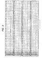
- Fig. 2 is a table showing an example of a gray code pattern of the absolute angle detecting device according to the first embodiment of the present invention.
- Fig. 3 is a graph showing a fail-safe characteristic of the absolute angle detecting device according to the first embodiment of the present invention.
- the absolute angle detecting device comprises a rotary disk 1, a first code pattern row 2 and a second code pattern row 3, each provided on the circumference whose center is the center of rotation O of the rotary disk 1 with its one sector being 180 degrees, a first detecting element group 10 consisting of five detecting elements 4, 5, 6, 7, and 8 that are arranged at equal intervals opposite to the first code pattern row 2, a second detecting element group 14 consisting of three detecting elements 11, 12, and 13 that are arranged at equal intervals opposite to the second code pattern row 3, converting means 15 for respectively converting five codes supplied from the first detecting element group 10 and three codes supplied from the second detecting element group 14 into rotation angles for the rotary disk 1, and a circuit board 16 on which the respective detecting elements 4 to 8 and 11 to 13, and the converting means 15 are mounted.
- the first code pattern row 2 and the second code pattern row 3 are formed of an optical pattern, such as a transparent hole or a cut-out portion, a magnetic pattern, or a resistor pattern, respectively.
- the detecting elements 4 to 8 and 11 to 13 are selected according to the configuration of the code pattern rows 2 and 3. That is, when the code pattern rows 2 and 3 are composed of an optical pattern, respectively, photointerrupters are used as the detecting elements 4 to 8 and 11 to 13.
- photointerrupters are used as the detecting elements 4 to 8 and 11 to 13.
- the code pattern rows 2 and 3 are composed of a magnetic pattern, respectively, magnetic detecting elements are used.
- the code pattern rows 2 and 3 are composed of a resistor pattern, respectively, collecting brushes are used.
- the converting means 15 converts the codes detected by the respective detecting elements 4 to 8 and 11 to 13 into rotation angles for the rotary disk 1 and comprises semiconductor integrated circuits and the like.
- the five detecting elements 4 to 8 constituting the first detecting element group 10 are arranged at pitches of 36 degrees opposite to the first code pattern row 2, and the three detecting elements 11 to 13 constituting the second detecting element group 14 are arranged at pitches of 60 degrees opposite to the second code pattern row 3.
- the first code pattern row 2 is composed of a six-step cyclic code obtained by combining six code strings each consisting of 5 bits, that is, (10000), (10100), (11100), (11110), (11010), and (11000), in which the same codes are not found even when read from any digit place.
- an absolute angle detecting device can be operated with high stability and reliability at the time of a failure.
- the second code pattern row 3 is formed such that the digit place of the 3-bit code strings obtained by combining the three codes supplied from the second detecting element group 14 are moved one bit by one bit whenever the same code strings are repeated in the 5-bit code strings obtained by combining the five codes supplied from the first detecting element group 10, or such that the digit place of the 3-bit code string is moved one by one whenever the rotary disk 1 is rotated by 60 degrees (40 steps). In this way, it is possible to achieve 8-bit gray codes as a whole only by repeating the 5-bit code strings, and thus to maintain a resolution of 1.5 degrees over one sector.
- Fig. 2 shows an example of a gray code pattern corresponding to one sector of the absolute angle detecting device according to the first embodiment of the present invention.
- signal C(n) to signal C(n + 4) represent codes respectively detected by the five detecting elements 4 to 8 that constitute the first detecting element group 10
- signal D(n) to signal D(n + 2) represent codes respectively detected by the three detecting elements 11 to 13 that constitute the second detecting element group 14.
- both the gray code obtained by combining the five codes supplied from the first detecting element group 10 and the gray code obtained by combining the three codes supplied from the second detecting element group 14 are composed of acyclic code with a resolution of 1.5 degrees.
- one sector may be 120 degrees, 90 degrees, 72 degrees, or 60 degrees.
- the resolution corresponding thereto can be 1.0 degrees, 0.75 degrees, 0.6 degrees, or 0.5 degrees, which can be easily handled and divided.
- the detection of an absolute angle is performed on one sector of 180 degrees.
- FIG. 4 is a view illustrating the structure of the absolute angle detecting device according to the second embodiment.
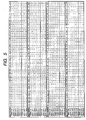
- Fig. 5 is a table showing an example of a gray code pattern of the absolute angle detecting device according to the second embodiment.
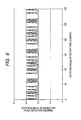
- Fig. 6 is a graph showing a fail-safe characteristic of the absolute angle detecting device according to the second embodiment.
- the absolute angle detecting device comprises a rotary disk 21, a first code pattern row 22 and a second code pattern row 23, each provided on the circumference whose center is the center of rotation O of the rotary disk 21 with its one sector being 180 degrees, a first detecting element group 30 consisting of six detecting elements 24, 25, 26, 27, 28, and 29 that are arranged at equal intervals opposite to the first code pattern row 22, a second detecting element group 34 consisting of three detecting elements 31, 32, and 33 that are arranged at equal intervals to be opposite to the second code pattern row 23, converting means 35 for respectively converting six codes supplied from the first detecting element group 30 and three codes supplied from the second detecting element group 34 into rotation angles for the rotary disk 21, and a circuit board 36 on which the respective detecting elements 24 to 29 and 31 to 33, and the converting means 35 are mounted.
- the first code pattern row 22 and the second code pattern row 23 are formed of an optical pattern, such as a transparent hole or a cut-out portion, a magnetic pattern, or a resistor pattern, respectively.
- the detecting elements 24 to 29 and 31 to 33 are selected according to the configuration of the code pattern rows 22 and 23. That is, when the code pattern rows 22 and 23 are composed of an optical pattern, respectively, photointerrupters are used as the detecting elements 24 to 29 and 31 to 33.
- the code pattern rows 22 and 23 are composed of a magnetic pattern, respectively, magnetic detecting elements are used.
- the code pattern rows 22 and 23 are composed of a resistor pattern, respectively, collecting brushes are used.
- the converting means 35 converts the codes detected by the respective detecting elements 24 to 29 and 31 to 33 into rotation angles for the rotary disk 21 and comprises semiconductor integrated circuits and the like.
- the six detecting elements 24 to 29 constituting the first detecting element group 30 are arranged at pitches of 30 degrees opposite to the first code pattern row 22, and the three detecting elements 31 to 33 constituting the second detecting element group 34 are arranged at pitches of 60 degrees opposite to the second code pattern row 23.
- the first code pattern row 22 is composed of a eight-step cyclic code obtained by combining eight code strings of 6 bits selected from nine code strings of 6 bits, that is, (100000), (110000), (101000), (111000), (110100), (101100), (111100), (111010), and (111110), in which the same code is not found even when read from any digit place.
- the number of repetitions of the respective code strings A, B, C, D, E, F, G, and H is preferably equal to or approximate to each other as much as possible such that the maximum number of repetitions is small.
- n A + n B + n C + n D + n E + n F + n G + n H 20; and n A , n B , n C , n D , n E , n F , n G , and n H each have a value of 2 or 3.
- the second code pattern row 23 is formed such that the digit place of the 3-bit code strings obtained by combining the three codes supplied from the second detecting element group 34 are moved one bit by one bit whenever the same code strings are repeated in the 6-bit code strings obtained by combining the six codes supplied from the first detecting element group 30, or such that the digit place of the 3-bit code string is moved one bit by one bit whenever the rotary disk 21 is rotated by 60 degrees corresponding to 40 steps.
- Fig. 5 shows an example of a gray code pattern' corresponding to one sector of the absolute angle 'detecting device according to the second embodiment of the present invention.
- signal C(n) to signal C(n + 5) represent codes respectively detected by the six detecting elements 24 to 29 that constitute the first detecting element group 30, and signal D(n) to signal D(n + 2) represent codes respectively detected by the three detecting elements 31 to 33 that constitute the second detecting element group 34.
- signal C(n) to signal C(n + 5) represent codes respectively detected by the six detecting elements 24 to 29 that constitute the first detecting element group 30
- signal D(n) to signal D(n + 2) represent codes respectively detected by the three detecting elements 31 to 33 that constitute the second detecting element group 34.
- both the gray code obtained by combining the six codes supplied from the first detecting element group 30 and the gray code obtained by combining the three codes supplied from the second detecting element group 34 are composed of a cyclic code with a resolution of 1.5 degrees.
- one sector may be 120 degrees, 90 degrees, 72 degrees, or 60 degrees.
- the resolution corresponding thereto can be 1.0 degrees, 0.75 degrees, 0.6 degrees, or 0.5 degrees, which can be easily divided and handled.
- the detection of an absolute angle is performed on one sector of 180 degrees.
Landscapes
- Physics & Mathematics (AREA)
- General Physics & Mathematics (AREA)
- Transmission And Conversion Of Sensor Element Output (AREA)
- Optical Transform (AREA)
Applications Claiming Priority (4)
| Application Number | Priority Date | Filing Date | Title |
|---|---|---|---|
| JP2003204663 | 2003-07-31 | ||
| JP2003204661 | 2003-07-31 | ||
| JP2003204661 | 2003-07-31 | ||
| JP2003204663 | 2003-07-31 |
Publications (2)
| Publication Number | Publication Date |
|---|---|
| EP1503185A2 true EP1503185A2 (fr) | 2005-02-02 |
| EP1503185A3 EP1503185A3 (fr) | 2012-01-25 |
Family
ID=33543574
Family Applications (1)
| Application Number | Title | Priority Date | Filing Date |
|---|---|---|---|
| EP04017751A Withdrawn EP1503185A3 (fr) | 2003-07-31 | 2004-07-27 | Capteur d'angle absolu |
Country Status (4)
| Country | Link |
|---|---|
| US (1) | US6966118B2 (fr) |
| EP (1) | EP1503185A3 (fr) |
| KR (1) | KR100538971B1 (fr) |
| CN (1) | CN1328575C (fr) |
Cited By (9)
| Publication number | Priority date | Publication date | Assignee | Title |
|---|---|---|---|---|
| EP1731876A1 (fr) * | 2005-06-07 | 2006-12-13 | Alps Electric Co., Ltd. | Dispositif de détection d'angle absolu |
| WO2007116090A1 (fr) * | 2006-04-12 | 2007-10-18 | Novo Nordisk A/S | Détermination de position absolue d'élément monté mobile dans un dispositif d'administration de médicaments |
| US7922096B2 (en) | 2000-08-10 | 2011-04-12 | Novo Nordisk A/S | Support for a cartridge for transferring an electronically readable item of information from the cartridge to an electronic circuit |
| US8049519B2 (en) | 2006-04-26 | 2011-11-01 | Novo Nordisk A/S | Contact free absolute position determination of a moving element in a medication delivery device |
| US8197449B2 (en) | 2005-05-10 | 2012-06-12 | Novo Nordisk A/S | Injection device comprising an optical sensor |
| US8348904B2 (en) | 2007-03-21 | 2013-01-08 | Novo Nordisk A/S | Medical delivery system having container recognition and container for use with the medical delivery system |
| US8608079B2 (en) | 2006-03-20 | 2013-12-17 | Novo Nordisk A/S | Contact free reading of cartridge identification codes |
| CN107885943A (zh) * | 2017-11-16 | 2018-04-06 | 山信软件股份有限公司 | 一种高炉溜槽倾动角度计算方法 |
| US9950117B2 (en) | 2009-02-13 | 2018-04-24 | Novo Nordisk A/S | Medical device and cartridge |
Families Citing this family (9)
| Publication number | Priority date | Publication date | Assignee | Title |
|---|---|---|---|---|
| EP1528369B1 (fr) * | 2003-10-27 | 2014-03-12 | SICK STEGMANN GmbH | Capteur d'angle de rotation optique |
| KR100665840B1 (ko) * | 2004-12-10 | 2007-01-09 | 삼성전자주식회사 | 데이지 체인 구조의 메모리 모듈 및 그의 형성 방법 |
| CN100460823C (zh) * | 2005-04-22 | 2009-02-11 | 阿尔卑斯电气株式会社 | 绝对角检测装置 |
| US7365654B2 (en) * | 2005-04-22 | 2008-04-29 | Alps Electric Co., Ltd | Absolute angle detection apparatus |
| RU2432549C2 (ru) | 2005-09-22 | 2011-10-27 | Ново Нордиск А/С | Способ и прибор для бесконтактного определения абсолютного положения и устройство, снабженное данным прибором |
| JP4617368B2 (ja) * | 2008-03-25 | 2011-01-26 | 山洋電気株式会社 | バッテリレス絶対位置検出用エンコーダ |
| US20140260522A1 (en) * | 2013-03-14 | 2014-09-18 | The Raymond Corporation | Home position indicator, encoder position measurement system including a home position indicator, and a method of detecting a home position |
| GB202015773D0 (en) * | 2020-10-05 | 2020-11-18 | Renishaw Plc | Apparatus, disc, and method of manufacture |
| JP2024148814A (ja) * | 2023-04-06 | 2024-10-18 | 株式会社ミツトヨ | 計測装置及びアブソリュート角度特定方法 |
Family Cites Families (13)
| Publication number | Priority date | Publication date | Assignee | Title |
|---|---|---|---|---|
| JPS58500911A (ja) * | 1981-03-04 | 1983-06-02 | ド−ルトン,ロム | 携帯用情報装置 |
| US4633224A (en) * | 1985-05-06 | 1986-12-30 | Caterpillar Inc. | Absolute and incremental optical encoder |
| DE3737278A1 (de) * | 1986-11-04 | 1988-05-11 | Canon Kk | Verfahren und vorrichtung zum optischen erfassen der stellung eines objekts |
| JPH01240820A (ja) * | 1988-03-23 | 1989-09-26 | Tokyo Keiki Co Ltd | 位置情報発生装置および該装置用符号配列体 |
| US4945231A (en) * | 1988-06-02 | 1990-07-31 | Toyota Jidosha Kabushiki Kaisha | Compound rotary encoder for detecting the rotation angle and the number of rotations of a rotor shaft |
| US5438330A (en) * | 1991-10-28 | 1995-08-01 | Nikon Corporation | Absolute encoder |
| US5445152A (en) * | 1992-11-23 | 1995-08-29 | Resonex Holding Company | Kinematic device for producing precise incremental flexing of the knee |
| US5739775A (en) * | 1993-07-22 | 1998-04-14 | Bourns, Inc. | Digital input and control device |
| JPH08219812A (ja) * | 1995-02-15 | 1996-08-30 | Canon Inc | 変位情報検出装置、変位情報検出用スケール及びこれを用いたドライブ制御装置 |
| JP2000028396A (ja) | 1998-07-07 | 2000-01-28 | Matsushita Electric Ind Co Ltd | 角度検出装置 |
| US6170162B1 (en) * | 1999-05-27 | 2001-01-09 | Sarcos, L.C. | Rotary displacement system using differential measuring |
| EP1321745A4 (fr) * | 2000-09-25 | 2005-09-07 | Tokai Rika Co Ltd | Detecteur d'angle tournant |
| DE10056604A1 (de) * | 2000-11-15 | 2002-05-23 | Kostal Leopold Gmbh & Co Kg | Verfahren zur Signalauswertung einer optoelektronischen Weg-oder Winkelmeßeinrichtung sowie Verwendung eines solchen Verfahrens |
-
2004
- 2004-07-27 CN CNB2004100549636A patent/CN1328575C/zh not_active Expired - Fee Related
- 2004-07-27 EP EP04017751A patent/EP1503185A3/fr not_active Withdrawn
- 2004-07-28 US US10/900,892 patent/US6966118B2/en not_active Expired - Fee Related
- 2004-07-30 KR KR10-2004-0060075A patent/KR100538971B1/ko not_active Expired - Fee Related
Cited By (14)
| Publication number | Priority date | Publication date | Assignee | Title |
|---|---|---|---|---|
| US7922096B2 (en) | 2000-08-10 | 2011-04-12 | Novo Nordisk A/S | Support for a cartridge for transferring an electronically readable item of information from the cartridge to an electronic circuit |
| US8771238B2 (en) | 2005-05-10 | 2014-07-08 | Novo Nordisk A/S | Injection device comprising an optical sensor |
| US8197449B2 (en) | 2005-05-10 | 2012-06-12 | Novo Nordisk A/S | Injection device comprising an optical sensor |
| US9522238B2 (en) | 2005-05-10 | 2016-12-20 | Novo Nordisk A/S | Injection device comprising an optical sensor |
| US7256713B2 (en) | 2005-06-07 | 2007-08-14 | Lg.Philips Lcd Co., Ltd. | Absolute angle detecting device |
| EP1731876A1 (fr) * | 2005-06-07 | 2006-12-13 | Alps Electric Co., Ltd. | Dispositif de détection d'angle absolu |
| US8608079B2 (en) | 2006-03-20 | 2013-12-17 | Novo Nordisk A/S | Contact free reading of cartridge identification codes |
| WO2007116090A1 (fr) * | 2006-04-12 | 2007-10-18 | Novo Nordisk A/S | Détermination de position absolue d'élément monté mobile dans un dispositif d'administration de médicaments |
| CN101421913B (zh) * | 2006-04-12 | 2012-07-18 | 诺沃-诺迪斯克有限公司 | 药品传输设备中的可移动安装元件的绝对位置的确定 |
| US8049519B2 (en) | 2006-04-26 | 2011-11-01 | Novo Nordisk A/S | Contact free absolute position determination of a moving element in a medication delivery device |
| US8348904B2 (en) | 2007-03-21 | 2013-01-08 | Novo Nordisk A/S | Medical delivery system having container recognition and container for use with the medical delivery system |
| US9950117B2 (en) | 2009-02-13 | 2018-04-24 | Novo Nordisk A/S | Medical device and cartridge |
| CN107885943A (zh) * | 2017-11-16 | 2018-04-06 | 山信软件股份有限公司 | 一种高炉溜槽倾动角度计算方法 |
| CN107885943B (zh) * | 2017-11-16 | 2021-04-09 | 山信软件股份有限公司 | 一种高炉溜槽倾动角度计算方法 |
Also Published As
| Publication number | Publication date |
|---|---|
| KR100538971B1 (ko) | 2005-12-26 |
| US6966118B2 (en) | 2005-11-22 |
| US20050022396A1 (en) | 2005-02-03 |
| CN1328575C (zh) | 2007-07-25 |
| CN1580707A (zh) | 2005-02-16 |
| KR20050014739A (ko) | 2005-02-07 |
| EP1503185A3 (fr) | 2012-01-25 |
Similar Documents
| Publication | Publication Date | Title |
|---|---|---|
| US6966118B2 (en) | Absolute angle detecting device | |
| US5880683A (en) | Absolute digital position encoder | |
| US8492704B2 (en) | Encoder and method of precisely indicating positions of one member relative to a second member | |
| US20090152452A1 (en) | Reflective multi-turn encoder | |
| US4730110A (en) | Shaft position encoder | |
| US7579829B1 (en) | Inductive multi-turn encoder | |
| US5049879A (en) | Position encoder utilizer special gray code | |
| KR100888009B1 (ko) | 절대각 검출장치 | |
| CN102209882B (zh) | 光学编码器 | |
| US7365654B2 (en) | Absolute angle detection apparatus | |
| JP4527465B2 (ja) | 絶対角検出装置 | |
| US7256713B2 (en) | Absolute angle detecting device | |
| US7521669B2 (en) | Multi-bit absolute position optical encoder with reduced number of tracks | |
| JP2008275517A (ja) | 多回転絶対角検出装置 | |
| US20080275665A1 (en) | Absolute angle detecting device | |
| JP2006194773A (ja) | 絶対角検出装置 | |
| CN100476362C (zh) | 绝对角检测装置 | |
| JP2006194774A (ja) | 絶対角検出装置 | |
| US7289041B2 (en) | Absolute position chain encoder | |
| GB2130034A (en) | Position detecting apparatus | |
| JP2691943B2 (ja) | 1トラック型アブソリュート・エンコーダ | |
| JP2006084347A (ja) | 絶対角検出装置 | |
| JP3094416B2 (ja) | アブソリュートエンコーダ | |
| JP2001141445A (ja) | 角度検出装置 | |
| JPH0622333B2 (ja) | 絶対位置検出用パルスエンコ−ダ |
Legal Events
| Date | Code | Title | Description |
|---|---|---|---|
| PUAI | Public reference made under article 153(3) epc to a published international application that has entered the european phase |
Free format text: ORIGINAL CODE: 0009012 |
|
| AK | Designated contracting states |
Kind code of ref document: A2 Designated state(s): AT BE BG CH CY CZ DE DK EE ES FI FR GB GR HU IE IT LI LU MC NL PL PT RO SE SI SK TR |
|
| AX | Request for extension of the european patent |
Extension state: AL HR LT LV MK |
|
| PUAL | Search report despatched |
Free format text: ORIGINAL CODE: 0009013 |
|
| AK | Designated contracting states |
Kind code of ref document: A3 Designated state(s): AT BE BG CH CY CZ DE DK EE ES FI FR GB GR HU IE IT LI LU MC NL PL PT RO SE SI SK TR |
|
| AX | Request for extension of the european patent |
Extension state: AL HR LT LV MK |
|
| RIC1 | Information provided on ipc code assigned before grant |
Ipc: G01D 5/249 20060101AFI20111221BHEP |
|
| AKY | No designation fees paid | ||
| REG | Reference to a national code |
Ref country code: DE Ref legal event code: R108 |
|
| REG | Reference to a national code |
Ref country code: DE Ref legal event code: R108 Effective date: 20121004 |
|
| STAA | Information on the status of an ep patent application or granted ep patent |
Free format text: STATUS: THE APPLICATION IS DEEMED TO BE WITHDRAWN |
|
| 18D | Application deemed to be withdrawn |
Effective date: 20120726 |