EP1503206A1 - Systèmes et méthodes pour identifier des objets étrangers et des débris et des défauts pendant la fabrication d'une structure composée - Google Patents
Systèmes et méthodes pour identifier des objets étrangers et des débris et des défauts pendant la fabrication d'une structure composée Download PDFInfo
- Publication number
- EP1503206A1 EP1503206A1 EP04076900A EP04076900A EP1503206A1 EP 1503206 A1 EP1503206 A1 EP 1503206A1 EP 04076900 A EP04076900 A EP 04076900A EP 04076900 A EP04076900 A EP 04076900A EP 1503206 A1 EP1503206 A1 EP 1503206A1
- Authority
- EP
- European Patent Office
- Prior art keywords
- composite structure
- camera
- light source
- light
- images
- Prior art date
- Legal status (The legal status is an assumption and is not a legal conclusion. Google has not performed a legal analysis and makes no representation as to the accuracy of the status listed.)
- Granted
Links
Images

Classifications
-
- D—TEXTILES; PAPER
- D06—TREATMENT OF TEXTILES OR THE LIKE; LAUNDERING; FLEXIBLE MATERIALS NOT OTHERWISE PROVIDED FOR
- D06H—MARKING, INSPECTING, SEAMING OR SEVERING TEXTILE MATERIALS
- D06H3/00—Inspecting textile materials
- D06H3/08—Inspecting textile materials by photo-electric or television means
-
- G—PHYSICS
- G01—MEASURING; TESTING
- G01N—INVESTIGATING OR ANALYSING MATERIALS BY DETERMINING THEIR CHEMICAL OR PHYSICAL PROPERTIES
- G01N21/00—Investigating or analysing materials by the use of optical means, i.e. using sub-millimetre waves, infrared, visible or ultraviolet light
- G01N21/84—Systems specially adapted for particular applications
- G01N21/88—Investigating the presence of flaws or contamination
- G01N21/94—Investigating contamination, e.g. dust
-
- B—PERFORMING OPERATIONS; TRANSPORTING
- B29—WORKING OF PLASTICS; WORKING OF SUBSTANCES IN A PLASTIC STATE IN GENERAL
- B29C—SHAPING OR JOINING OF PLASTICS; SHAPING OF MATERIAL IN A PLASTIC STATE, NOT OTHERWISE PROVIDED FOR; AFTER-TREATMENT OF THE SHAPED PRODUCTS, e.g. REPAIRING
- B29C70/00—Shaping composites, i.e. plastics material comprising reinforcements, fillers or preformed parts, e.g. inserts
- B29C70/04—Shaping composites, i.e. plastics material comprising reinforcements, fillers or preformed parts, e.g. inserts comprising reinforcements only, e.g. self-reinforcing plastics
- B29C70/28—Shaping operations therefor
- B29C70/54—Component parts, details or accessories; Auxiliary operations, e.g. feeding or storage of prepregs or SMC after impregnation or during ageing
-
- D—TEXTILES; PAPER
- D06—TREATMENT OF TEXTILES OR THE LIKE; LAUNDERING; FLEXIBLE MATERIALS NOT OTHERWISE PROVIDED FOR
- D06H—MARKING, INSPECTING, SEAMING OR SEVERING TEXTILE MATERIALS
- D06H3/00—Inspecting textile materials
-
- G—PHYSICS
- G01—MEASURING; TESTING
- G01N—INVESTIGATING OR ANALYSING MATERIALS BY DETERMINING THEIR CHEMICAL OR PHYSICAL PROPERTIES
- G01N21/00—Investigating or analysing materials by the use of optical means, i.e. using sub-millimetre waves, infrared, visible or ultraviolet light
- G01N21/84—Systems specially adapted for particular applications
- G01N21/88—Investigating the presence of flaws or contamination
- G01N21/8806—Specially adapted optical and illumination features
-
- G—PHYSICS
- G01—MEASURING; TESTING
- G01N—INVESTIGATING OR ANALYSING MATERIALS BY DETERMINING THEIR CHEMICAL OR PHYSICAL PROPERTIES
- G01N21/00—Investigating or analysing materials by the use of optical means, i.e. using sub-millimetre waves, infrared, visible or ultraviolet light
- G01N21/84—Systems specially adapted for particular applications
- G01N21/88—Investigating the presence of flaws or contamination
- G01N21/95—Investigating the presence of flaws or contamination characterised by the material or shape of the object to be examined
-
- B—PERFORMING OPERATIONS; TRANSPORTING
- B29—WORKING OF PLASTICS; WORKING OF SUBSTANCES IN A PLASTIC STATE IN GENERAL
- B29C—SHAPING OR JOINING OF PLASTICS; SHAPING OF MATERIAL IN A PLASTIC STATE, NOT OTHERWISE PROVIDED FOR; AFTER-TREATMENT OF THE SHAPED PRODUCTS, e.g. REPAIRING
- B29C37/00—Component parts, details, accessories or auxiliary operations, not covered by group B29C33/00 or B29C35/00
- B29C2037/90—Measuring, controlling or regulating
- B29C2037/906—Measuring, controlling or regulating using visualisation means or linked accessories, e.g. screens, printers
-
- G—PHYSICS
- G01—MEASURING; TESTING
- G01N—INVESTIGATING OR ANALYSING MATERIALS BY DETERMINING THEIR CHEMICAL OR PHYSICAL PROPERTIES
- G01N21/00—Investigating or analysing materials by the use of optical means, i.e. using sub-millimetre waves, infrared, visible or ultraviolet light
- G01N21/84—Systems specially adapted for particular applications
- G01N2021/8472—Investigation of composite materials
-
- G—PHYSICS
- G01—MEASURING; TESTING
- G01N—INVESTIGATING OR ANALYSING MATERIALS BY DETERMINING THEIR CHEMICAL OR PHYSICAL PROPERTIES
- G01N21/00—Investigating or analysing materials by the use of optical means, i.e. using sub-millimetre waves, infrared, visible or ultraviolet light
- G01N21/84—Systems specially adapted for particular applications
- G01N21/88—Investigating the presence of flaws or contamination
- G01N21/8806—Specially adapted optical and illumination features
- G01N2021/8822—Dark field detection
- G01N2021/8825—Separate detection of dark field and bright field
-
- G—PHYSICS
- G01—MEASURING; TESTING
- G01N—INVESTIGATING OR ANALYSING MATERIALS BY DETERMINING THEIR CHEMICAL OR PHYSICAL PROPERTIES
- G01N33/00—Investigating or analysing materials by specific methods not covered by groups G01N1/00 - G01N31/00
- G01N33/36—Textiles
Definitions
- the present invention relates generally to the fabrication of composite structures, and more particularly to systems and methods for locating foreign objects and debris (FOD) and defects during fabrication of a composite structure.
- FOD foreign objects and debris
- Composite structures have been known in the art for many years. Although composite structures can be formed in many different manners, one advantageous technique for forming composite structures is a fiber placement or automated collation process. According to conventional automated collation techniques, one or more ribbons of composite material (also known as composite strands or tows) are laid down on a substrate.
- the substrate may be a tool or mandrel, but, more conventionally, is formed of one or more underlying layers of composite material that have been previously laid down and compacted.
- Conventional fiber placement processes utilize a heat source to assist in compaction of the plies of composite material at a localized nip point.
- the ribbon or tow of composite material and the underlying substrate are heated at the nip point to increase the tack of the resin of the plies while being subjected to compressive forces to ensure adhesion to the substrate.
- additional strips of composite material can be applied in a side-by-side manner to each layer and can be subjected to localized heat and pressure during the consolidation process.
- defects can occur during the placement of the composite strips onto the underlying composite structure. Such defects can include tow gaps, overlaps, dropped tows, puckers, and twists. Additionally, foreign objects and debris (FOD), such as resin balls and fuzz balls, can accumulate on a surface of the composite structure. Resin balls are small pieces of neat resin that build up on the surfaces of the fiber placement head as the preimpregnated tows pass through the guides and cutters. The resin balls become dislodged due to the motion and vibration of the fiber placement machine, and drop on to the surface of the ply. If not removed, subsequent courses will cover the resin ball and create a bump in the laminate whereat there may be no compaction of the tows.
- FOD foreign objects and debris
- Fuzz balls are formed when fibers fray at the edges of the tows and then break off as the tows are passed through the cutter assembly. The broken fibers collect in small clumps that fall onto the laminate and, if not removed, are covered by the next course.
- Composite laminates fabricated by fiber placement processes are typically subjected to a 100% ply-by-ply visual inspection for both defects and FOD. Typically, these inspections are performed manually during which time the fiber placement machine is stopped and the process of laying materials halted until the inspection and subsequent repairs, if any, are completed. In the meantime, the fabrication process has been disadvantageously slowed by the manual inspection process and machine downtime associated therewith.
- the system includes at least one light source positioned to emit light that illuminates a portion of the composite structure with bright field illumination and that also illuminates another portion of the composite structure with dark field illumination.
- the bright field illumination is reflected differently by defects in the composite structure than from portions of the composite structure that are defect free.
- the dark field illumination is reflected differently by FOD on the composition structure than from surfaces of the composite structure that are FOD free.
- the system also includes at least one camera for receiving images of the illuminated portions of the composite structure.
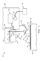
- Figure 1 is a schematic view of a system for identifying FOD and defects during fabrication of a composite structure according to one embodiment of the present invention
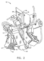
- Figure 2 is a perspective view of a system for identifying FOD and defects during fabrication of a composite structure according to another embodiment of the present invention
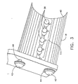
- Figure 3 is a perspective view of a light source according to the embodiment of the system shown in Figure 2;
- Figure 4 is a perspective view of a system for identifying FOD and defects during fabrication of a composite structure according to another embodiment of the present invention.
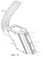
- Figure 5 is a perspective view of a light source according to the embodiment of the system shown in Figure 4;
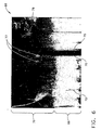
- Figure 6 is a video frame capturing both FOD and a gap between tows as captured by one embodiment of the present invention
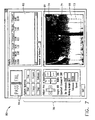
- Figure 7 is a view of a computer display and selected user controls according to one embodiment of the present invention.
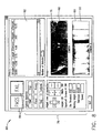
- Figure 8 is a view of a computer display and selected user controls according to another embodiment of the present invention.
- Embodiments of systems for identifying foreign objects and debris (FOD) and defects during fabrication of a composite structure are generally indicated by reference numeral 10 in Figures 1, 2 and 4.
- the system 10 is positioned proximate a composite structure 22, which is generally comprised of a plurality of adjacent tows or strips 24 of composite tape.
- the strips 24 typically include a plurality of fibers embedded in a resin or other material that becomes tacky or flowable upon the application of heat.
- the strips 24 are arranged on a work surface, such as a table, mandrel, or other tool 26, and compacted with a compaction roller 20 ( Figure 2) to form the composite structure 22 according to an automated collation technique, such as that described in U.S. Patent Application No.
- the system 10 includes at least one camera 12 and at least one light source 14.
- the camera 12 is connected to a processor 66 for interpreting the images the camera 12 captures, or to a storage device 64 for storing the images, or both, as discussed more fully below.
- the light source 14 is positioned to emit light that illuminates a first portion 17 of the composite structure 22 with bright field illumination (also known as incident light) while also illuminating a second portion 19 with dark field illumination (also known as indirect light). More specifically, the bright field illumination "spills" over onto the second portion 19 of the composite structure 22 and illuminates the second portion 19 with dark field illumination.
- bright field illumination also known as incident light
- dark field illumination also known as indirect light
- the bright field illumination is reflected differently by defects in the composite structure than from portions of the composite structure that are defect free.
- the bright field illumination reflecting off non-defective portions of the composite structure 22, and light that fails to reflect off of defects in the composite structure 22, or vice versa creates visible images that can be captured by the camera 12.
- Details regarding systems and methods for identifying defects in a composite structure during fabrication thereof are included in U.S. Patent Application No. 09/819,922, filed on March 28, 2001, entitled “System and Method for Identifying Defects in a Composite Structure” and in U.S. Patent Application No. 10/217,805, filed on August 13, 2002, entitled “System for Identifying Defects in a Composite Structure".
- the contents of U.S. Patent Application Nos. 09/819,922 and 10/217,805 are incorporated herein by reference as if fully set forth herein.
- the dark field illumination is reflected differently by FOD on the composition structure 22 than from surfaces of the composite structure that are FOD free.
- the dark field illumination reflecting off FOD, such as resin balls and fuzz balls, on the composite structure 22, and the dark field illumination that fails to reflect off the FOD-free portions of the composite structure 22, or vice versa creates visible images that can also be captured by the camera 12, as discussed in detail below.
- the camera 12 is positioned near the composite structure 22 so as to capture images of the illuminated portions 17 and 19 of the composite structure 22, which are typically immediately downstream of the nip point at which a composite tow is joined with the underlying structure.
- a reflective surface 16 may be positioned near the composite structure (not shown in Figure 2), and angled such that the reflective surface 16 reflects an image of the illuminated portions 17 of the composite structure.
- the angle of the reflective surface 16 to the composite structure is about sixty-five degrees, but the reflective surface 16 can also be positioned at any appropriate angle in order to reflect images of the illuminated portions of the composite structure to the camera 12.
- the camera 12 then may be positioned to point toward the reflective surface 16 in order to capture the close-range images of the illuminated portions of the composite structure from the reflective surface 16. More than one reflective surface 16 may also be utilized in further embodiments of the present invention in which the reflective surfaces 16 cooperate in order to direct images of the illuminated portions of the composite structure to the camera 12.
- an image of the composite structure is advantageously captured from a position as close as possible to the nip point in order to obtain an accurate representation of the composite structure for processing.
- the configuration illustrated in Figure 2 is particularly advantageous for capturing images of curved/contoured surfaces of the composite structure because the reflective surface 16 reflects images of the composite structure for the camera 12 to capture from a position as close as possible to the composite structure.
- this configuration permits the camera 12 to be placed further from the composite structure than the reflective surface 16, such that the camera 12 does not obstruct the functionality of other parts of the fiber placement device, or vice versa.
- the reflective surface 16 can also provide a "square on" view of the area being inspected, which, in turn, can materially improve the ability to dimension the two gaps for pass/fail decisions.
- the camera 12 is a television or other type of video camera having an image sensor (not shown) and a lens 13 through which light passes when the camera 12 is in operation.
- Other types of cameras or image sensors can also be used, such as an infrared-sensitive camera, a visible light camera with infrared-pass filtration, a fiber optic camera, a coaxial camera, Charge Coupled Device (CCD), or Complementary Metal Oxide Sensor (CMOS).
- the camera 12 can be positioned proximate the composite structure 22 on a stand (not shown) or mounted to a frame 28 or similar device. In embodiments of the present invention that do not include a reflective surface 16, the camera 12 may be positioned approximately six inches from the surface of the composite structure 22, and mounted to the frame 28 by way of a bracket 30 and associated connectors 32, as shown in Figure 1.
- the reflective surface 16 may be positioned approximately three inches from the surface of the composite structure 22, and the camera 12, pointed toward the reflective surface 16, may be positioned further away from the composite structure, as described above. In further embodiments of present invention, the reflective surface 16 may be positioned at other distances from the surface of the composite structure 22, such as from one to six inches, to accurately reflect an image of the surface of the composite structure toward the camera 12. Reflective surfaces can also be utilized to allow the camera to be placed in an advantageous position which might otherwise be blocked by portions of the compaction roller 20 ( Figure 2) and/or other parts of the fiber placement system.
- the connectors 32 may be rivets, screws or the like that mount the camera 12 to the frame 28 in a stationary position.
- the connectors 32 may be a hinge-type connector that permits the camera 12, light source 14, and associated assembly to be rotated away from the composite structure 22. This embodiment is advantageous in situations where other parts of the material placement device, particularly the parts located behind the camera 12 and associated assembly, must be accessed, such as for maintenance, cleaning, or the like.
- Figure 2 illustrates an alternative embodiment of the hinge-type connector 32 that mounts the camera 12, reflective surface 16, light source 14, and associated assembly (i.e., camera assembly) to the frame 28 by way of a bracket 30.
- a suitable fastener such as a thumbscrew or any other fastener that may be removed or loosened with relative ease, can be inserted through hole 34 and then tightened to secure the camera assembly in place for operation. The fastener may be loosened or removed, for example, to rotate the camera assembly away from the compaction roller 20 and other parts of the fiber placement device.
- a filter 15 can be placed on the lens 13 for filtering light in a particular manner.
- the filter 15 is designed to filter light such that only the infrared component or a certain infrared wavelength or range of wavelengths of light can pass into the camera 12.
- the filter 15 prevents ambient visible light from entering the camera 12 and altering the appearance of the captured image.
- the camera may be designed to include a built-in filter of equivalent optical characteristics.
- the filter can be located between the camera lens 13 and image sensor.
- the camera may include an image sensor that is only sensitive in the infrared spectrum (i.e., an infrared-sensitive camera), thus eliminating the need for the filter.
- the light source 14 of the system 10 will now be described in detail.
- the light source 14 is positioned to emit light that illuminates the first portion 17 of the composite structure 22 with bright field illumination (i.e., incident light) while also illuminating the second portion 19 with dark field illumination (i.e., indirect light).
- the bright field illumination "spills" over onto the second portion 19 and thus illuminates the second portion 19 with dark field illumination.
- the light source 14 is shown positioned at an oblique angle 37 relative to the composite structure 22.
- the oblique angle 37 may be about forty-five degrees, although other angles are possible depending on the application.
- the light source 14 is also shown positioned to emit light in a direction substantially perpendicular to the direction of placement of the strips 24 in order to highlight the defects 36, as described below.
- the system 10 may include more than one light source.
- the embodiment of Figure 2 includes two light sources 14 positioned relative to the composite structure and compaction roller 20 on either side of the reflective surface 16 and camera 12.
- Another exemplary embodiment that includes two light sources 14 is shown in Figure 4 in which two linear optical fiber arrays are positioned on opposed sides of the camera 12.
- the light source 14 is adjustably positioned relative to the composite structure 22 by mounting or attaching the light source 14 to a mounting apparatus 27.
- the mounting apparatus 27 can include a main shaft 29, a secondary shaft 31, and a locking clamp 33 for quickly and accurately adjusting the position of the light source 14.
- the mounting apparatus 27, in turn, can be attached to the frame 28, to the camera 12, to the bracket 30, or to some other object that defines a common position for both the light source 14 and the camera 12 such that the light source 14 and camera 12 maintain a constant spatial relationship relative to one another.
- the quality and magnitude of the surface illumination of the composite structure is greatly affected by ambient lighting and by the reflectivity of the material. Accordingly, embodiments of the invention advantageously employ an infrared light source to more effectively illuminate dark flaws on a dark background.
- the light source 14 can be selected from an infrared light or another type of light having an infrared component, such as a halogen light source ( Figure 3) or other incandescent light sources (not shown).
- the light source 14 can also include a fluorescent light source (e.g., white light LEDs, low pressure/mercury filled phosphor glass tube, etc.), a strobe or stroboscopic light source, a noble gas arc lamp (e.g., xenon arc, etc.), metal arc lamp (e.g., metal halide, etc.) and a lasers (e.g., pulsed lasers, solid state laser diode arrays, infrared diode laser arrays, etc.).
- the light from the light source 14 may also be pumped from through optical fibers to the point of delivery, such as is shown in Figure 4.
- the light source 14 is operated at a power level that maximizes, or at least significantly increases, the infrared (IR) component of the light which works well for inspecting dark tow material, such as carbon.
- IR infrared
- exemplary power levels in the range of up to about one hundred fifty watts (150W) in the wavelength range of about seven hundred nanometers to one thousand nanometers (700nm-1000nm) have been sufficient.
- the particular power levels and wavelengths for the light source will likely depend at least in part on the camera's speed and sensitivity, speed at which the material is being laid, delivery losses, and reflectivity of the material being inspected, among other factors.
- wavelengths and power levels suitable for inspecting highly reflective materials can be employed.
- the light source 14 may comprise a plurality of LEDs arranged in an array or cluster formation. In one specific embodiment, the light source 14 includes 24 LEDs mounted in an array upon a three-inch square printed circuit board.
- the light source 14 includes four halogen light bulbs 38, although other quantities can also be used.
- the bulbs 38 are either deactivated/turned off or covered with an opaque material.
- the bulbs 38 are coupled to a switching device that allows the operator to selectively activate and deactivate individual bulbs 38 and/or groups of the bulbs 38.
- the switching device can be implemented by conventional switches or by a control feature added to the user interface 76, described below.
- the light source 14 includes two linear optical fiber arrays positioned on opposite sides of the camera 12.
- the arrays emit light supplied from a remote source (not shown) through an optical fiber bundle 25.
- a portion 35 of each array 14 is blocked or covered with an opaque material, which effectively shortens the array 14.
- Figure 5 there is shown a linear array 14 in which the portion 35 is not covered and the entire array is fully illuminated.
- the system 10 may further include a light reflection element 18 located near the light source 14.
- the reflection element 18 include a series of light reflecting surfaces 40 ( Figure 3) that redirect the light towards the desired area to be illuminated. This levels the illumination across the surface and eliminates, or at least substantially reduce, areas of intense light (i.e., hotspots) created by the brightest portion of the light source 14. Hotspots are undesirable because hotspots prevent consistent illumination of the composite structure, which may lead to errors during the processing of the images captured by the camera 12.
- the light reflection elements 40 are particularly advantageous for illuminating curved/contoured surfaces of composite structures because the redirection of the light permits a larger portion of the composite structure to be evenly illuminated.
- the reflection element 18 is curved around the light source 14, such as in a parabolic shape.
- the reflection element 18 includes curved steps 40 substantially parallel to the light source 14.
- the distance between and curvature of the steps 40 can be chosen to be sufficient to provide even illumination from the sum of the two light sources, one on either side of the region of interest. This enables the reflection element 18 to provide more consistent illumination of the composite structure 22, which prevents, or at least reduces, image processing errors due to inconsistent illumination of the composite structure 22.
- the shape and/or surface configuration of the reflection element 18 can be modified in other ways that also produce consistent illumination and scattering of the light produced by the light source 14 over the desired portion of the composite structure 22.
- the reflection element 18 has an overall parabolic shape with seventeen parabolic curved steps 40 having a range of widths from about 0.125 inches at the outer edge of the reflection element 18 to about 0.250 inches at the center of the reflection element 18.
- the reflection element 18 also has a uniform step height of about 0.116 inches. In other embodiments, however, the reflection element may be provided with different numbers of steps having different uniform or varying widths and different uniform or varying step heights.
- the reflection element 18 may be adjusted in order to direct the light produced by the light source 14 and scattered by the reflection element 18 toward the desired portion of the composite structure.
- the reflection element 18 is adjustably mounted to the mounting apparatus 27 with fasteners 42.
- the loosened fasteners 42 can move within slots 44 to correspondingly adjust the angle of the reflection element 18 relative to the composite structure.
- the fasteners 42 are tightened to secure the reflection element 18 in the desired position.
- Adjustments of the reflection element 18 can also be enabled by other methods, such as by electronic means that permit remote adjustment of the reflection element 18.
- the composite structure 22 produces high glare when illuminated across the direction of placement of the strips 24 but produces substantially less glare when illuminated along the direction of placement of the strips 24.
- the systems and methods of at least some embodiments exploit the high-glare/low-glare phenomenon by casting light across the top layer of the composite strips 24 in a direction substantially perpendicular to the direction of placement of the strips 24. This produces a relatively large amount of glare on the top layer of the composite structure 22.
- the underlying layers which produce significantly less glare than the top layer because of their orientation, will show through any gaps or other defects in the top layer and thus be easily located.
- twists and other surface defects in the top layer will alter the orientation of the strips in the top layer and thus correspondingly alter, i.e., decrease, the glare of the top layer at the defect location.
- the filter 15 used in one embodiment of the system 10 substantially removes the glare caused by ambient light such that only the glare caused by the infrared light source is used to locate the defects and FOD. Accordingly, the filter 15 removes the interference of ambient light as the composite structure 22 is being examined for defects and FOD.
- the one or more cameras 12 and/or one or more light sources 14 may be moveable relative to the composite structure.
- the multiple cameras 12 and/or multiple light sources 14 and the moveability of the camera(s) 12 and/or the light source(s) provides system 10 flexibility in order to capture the most accurate images of the composite structure.
- Multiple and/or moveable light source(s) 14 permit consistent and sufficient illumination of the desired portion of the composite structure, regardless of the shape of the composite structure.
- multiple and/or moveable camera(s) 12 enable capturing an accurate image of any area of the composite structure, regardless of the shape of the composite structure.
- the multiple and/or moveable light source(s) and/or camera(s) are particularly advantageous when illuminating and capturing images of and curved/contoured portions of composite structures.
- the multiple and/or moveable light source(s) and/or camera(s) are also advantageous in illuminating and capturing images of composite strips having a width that makes it difficult to illuminate and/or capture images of the entire strip, such that the position of the light source(s) and/or camera(s) may be moved over the entire strip, and/or multiple stationary light source(s) and/or camera(s) may be positioned to cover the entire strip.
- Systems including moveable cameras and light sources are described in detail in previously referred to U.S. Patent Application No. 10/217,805.
- the system 10 can also include a marking device 62 for marking the location of the defects and FOD on the composite structure 22.
- the marking device 62 may be attached to the frame 28 and be triggered by a processor 66 or similar device when a defect 36 or FOD 21 that is to be reported to the operator is detected.
- the marking device 62 may spray or otherwise deposit an amount of ink, paint or the like onto the composite structure 22 in those areas where defects 36 and FOD has been detected.
- the markings on the composite structure 22 enables the location of the defects and/or FOD to be subsequently readily identified either automatically or manually.
- the marking device 62 is an inkjet marking system that sprays a small spot of compatible ink of a highly visible color onto the surface of the composite structure 22 at the defect or FOD location to permit rapid access for repair and disposition.
- the marking device 62 may also be adapted to mark FOD with a different colored ink than that used to mark defects.
- other marking methods can also be used, such as a pump-fed felt-tip marker, spring-loaded marking pen, audio or visual alerts, and the like.
- the automated collation process includes guiding the composite strips 24 (Figure 1) from material creels (not shown) to an automated collation or fiber placement machine, such as a machine made by Cincinnati-Milacron and Ingersoll Milling Machines.
- the composite strips 24 are guided to a head unit 23 ( Figure 3) and fed under a compaction roller 20. Focused heat energy is then applied to the incoming material and the underlying material that was previously laid to adhere the two materials. With the combination of pressure and heat, the composite strip 24 is consolidated into the previous layer, thus forming an additional layer of the composite structure 22.
- defects 36 may sometimes occur during the placement of the composite strip 24 onto the underlying composite structure 22 and/or FOD may accumulate on a surface of the composite structure.
- the camera 12 and/or the reflective surface 16, which along with the light source 14 and any reflection element 18, can be mounted to the head unit to allow the camera 12 to continuously capture real-time images of the composite structure 22 and the strips 24 as the head unit moves across the composite structure 22 and the composite strips 24 are laid down. If the composite structure 22 is not planar, the inspection point should be as close to the nip point as possible, as described above. If the composite structure 22 is planar, the inspection point can be located further from the placement head unit. In either case, the images can be stored in a memory device 64 for future analysis and/or processed immediately by the processor 66, as discussed more fully below.
- Figure 6 shows an exemplary raw or unprocessed camera image 68, which includes a plurality of pixels having a range from black through a plurality of shades of gray to white.
- the image 68 includes a bright field 69 and a dark field 71.
- the bright field 69 corresponds to the first portion 17 (Figure 1) of the composite structure illuminated with the bright field illumination
- the dark field 71 corresponds to the second portion 19 ( Figure 1) illuminated with the dark field illumination.
- the bright field 69 in the unprocessed camera image 68 illustrates a contrast between a potential defect 75, such as a tow gap, and the remaining portions of the composite structure 22 that are defect free.
- a potential defect 75 such as a tow gap
- the potential defects are shown as black or gray areas 70, while the remaining non-defective portions of the composite structure 22 remain substantially white 72. Once the potential defects are located, however, the potential defects may still require further processing to determine if the potential defects are acceptable or unacceptable, as described below.
- the dark field 71 of the unprocessed camera image 68 illustrates a contrast between the dark field illumination that is reflected by FOD and the remaining portions of the composite structure 22 that are FOD free.
- a resin ball is indicated by way of two substantially white reflection spots 77 visible on either side of the resin ball.
- a potential fuzz ball is shown as a substantially white area 79 indicative of the dark field illumination being reflected from the edges and fiber ends of the fuzz ball.
- the remaining FOD-free portions of the composite structure 22 remain black or gray.
- Further processing may also be needed to determine whether a potential FOD anomaly is acceptable or unacceptable according to maximum allowable dimensional parameters. That is, the system may only mark or flag FOD which exceed the maximum allowable dimensional parameters. To make this determination, the system may count the number of pixels within a particular image region that represents the reflected dark field illumination by a potential FOD anomaly. The system may then use the pixel count to compute an indirect quantitative measurement for the particular FOD anomaly based upon correlation data including a predetermined relationship between pixel count and FOD size.
- the processor 66 may receive the images 68 from the camera 12 or from the memory device 64 in which the images 68 have been stored. The processor 66 may then process and analyze the images to facilitate the reliable detection of defects and FOD.
- the processor 66 and memory device 64 are components of a conventional computer.
- the system 10 may also includes a user interface 76 that is in communication with the processor 66.
- the user interface 76 can be programmed such that it can run from a wide range of software applications, including but not limited to DOS, Windows 98, Windows/NT, Windows 2000, Windows CE, Linux, Unix, and equivalents.
- the user interface 76 includes a display screen 80, such as on a computer monitor, and can also include an input device, such as a keyboard and mouse (not shown), for permitting an operator to move a cursor about the display screen 80 and input various system settings and parameters.
- the display screen 80 can also be touch-sensitive for permitting the operator to input the desired settings by manually touching regions of the display screen.
- the user interface 76 includes a window 81 in which an image 74 of the composite structure 22 is displayed for viewing by the operator or other user.
- the image 74 can be the unprocessed camera image 68 ( Figure 6)
- the image 74 shown in Figure 7 is a processed image in which the rectangular region 73 has been binarized.
- all shades of gray above a predetermined threshold value can be changed to white, while all gray shades below the threshold are changed to black to heighten the contrast of defects and improve the accuracy of defect detection.
- the binarization step need not be performed but instead the raw image, rates of change of the light levels in the raw image, and/or color changes in the images can be used to identify the defects and FOD.
- the user interface 76 also provides user controls 78 for allowing various user inputs to the system.
- the user interface 76 allows adjustment to the binarization threshold.
- the setting of the binarization threshold involves a tradeoff between the sensitivity with which defects are detected and the resolution with which the defects are depicted.
- the binarization threshold is set to about 128 which corresponds to the mid-point on the 8-bit digitizing range of 0 to 255.
- other binarization threshold values can be employed depending at least in part on the particular application, available lighting, camera settings, among other factors.
- the user controls 78 also allow the user to adjust or shift the viewing area within the window 81.
- the window 81 displays real-time moving video images of the illuminated portions 17 and 19 of the composite structure 22 as the camera 12 and/or the reflective surface 18 are moved relative to the composite structure 22.
- the user can shift or adjust the window 81 such that the window 81 simultaneously displays both the bright field 69 and the dark field 71.
- the interface 76 may also allow the user to input the maximum allowable dimensional parameters for acceptable defects and FOD and/or input the acceptable tolerances of the maximum dimensional parameters, among others.
- the display screen 80 also includes a defect table 82 which lists the discovered defects and provides information for each defect, such as location, size, and the like.
- the display screen 80 can also include an FOD table (not shown) for listing and providing information about the discovered FOD anomalies.
- the display screen 80 can further include status indicators 84 that notify the user whether a particular image area is acceptable or not acceptable based on predefined criteria, such as maximum allowable dimensional parameters and tolerances.
- Figure 8 illustrates another embodiment of the user interface 76 that may be used in a system 10 that includes two or more cameras 12 for capturing images of the composite structure 22.
- the user interface 76 includes a display screen 86 that displays images 88 and 90 of the composite structure 22 for viewing by the operator or other user.
- the image 88 is captured by the first camera and represents the portion 17 of the composite structure 22 illuminated with bright field illumination.
- the dark field image 90 is captured by the second camera and represents the portion 19 of the composite structure 22 illuminated with dark field illumination.
- multiple user interfaces can be used to display the images of multiple cameras 12 in which each interface displays an image from one or more cameras and presents one or more links to the user interface(s) that display images from the other camera(s). Images from multiple cameras mounted side by side can be assembled to form a composite view of a larger area of the composite structure.
- the present invention provides methods for identifying FOD and defects during fabrication of a composite structure.
- the method generally comprises: illuminating a portion of the composite structure with bright field illumination; illuminating another portion of the composite structure with dark field illumination; acquiring an image of the illuminated portions of the composite structure; analyzing the image to identify defects in the portion of the composite structure illuminated by bright field illumination; and analyzing the image to identify foreign objects and debris on the another portion of the composite structure illuminated by dark field illumination.
- embodiments of the present invention can operate more efficiently with fewer interruptions than conventional fiber placement systems because human intervention is not required for inspection of the composite structure for defects and foreign objects and debris. Instead, the embodiments of the present invention can rapidly detect and identify defects and FOD so that the same can be subsequently readily identified during remedial actions to repair the defects and/or remove the FOD, which would otherwise create structural flaws or inconsistencies that may affect the integrity of the composite structure. As such, less material is wasted, less labor is expended in inspection, and less machine downtime is incurred during the fabrication process; therefore, a lower cost composite structure is achieved on average. Additionally, embodiments also enable an improvement in the overall quality of the parts produced because defects and FOD can be detected more uniformly and reliably with the various automated systems and methods of the invention than a traditional human inspection.
Landscapes
- Chemical & Material Sciences (AREA)
- Biochemistry (AREA)
- Immunology (AREA)
- Pathology (AREA)
- Physics & Mathematics (AREA)
- Health & Medical Sciences (AREA)
- Life Sciences & Earth Sciences (AREA)
- Engineering & Computer Science (AREA)
- General Health & Medical Sciences (AREA)
- Analytical Chemistry (AREA)
- General Physics & Mathematics (AREA)
- Composite Materials (AREA)
- Mechanical Engineering (AREA)
- Materials Engineering (AREA)
- Textile Engineering (AREA)
- Investigating Materials By The Use Of Optical Means Adapted For Particular Applications (AREA)
Applications Claiming Priority (4)
| Application Number | Priority Date | Filing Date | Title |
|---|---|---|---|
| US62869103A | 2003-07-28 | 2003-07-28 | |
| US628691 | 2003-07-28 | ||
| US10/846,974 US7236625B2 (en) | 2003-07-28 | 2004-05-14 | Systems and method for identifying foreign objects and debris (FOD) and defects during fabrication of a composite structure |
| US846974 | 2004-05-14 |
Publications (2)
| Publication Number | Publication Date |
|---|---|
| EP1503206A1 true EP1503206A1 (fr) | 2005-02-02 |
| EP1503206B1 EP1503206B1 (fr) | 2019-03-06 |
Family
ID=33544783
Family Applications (1)
| Application Number | Title | Priority Date | Filing Date |
|---|---|---|---|
| EP04076900.2A Expired - Lifetime EP1503206B1 (fr) | 2003-07-28 | 2004-07-01 | Systèmes et méthodes pour identifier des objets étrangers, des débris et des défauts pendant la fabrication d'une structure composée |
Country Status (5)
| Country | Link |
|---|---|
| US (1) | US7236625B2 (fr) |
| EP (1) | EP1503206B1 (fr) |
| JP (1) | JP4615919B2 (fr) |
| KR (1) | KR101102627B1 (fr) |
| CA (1) | CA2468126C (fr) |
Cited By (24)
| Publication number | Priority date | Publication date | Assignee | Title |
|---|---|---|---|---|
| WO2007021890A1 (fr) * | 2005-08-11 | 2007-02-22 | The Boeing Company | Systemes et procedes permettant d'assurer une inspection visuelle en cours de traitement pour des machines automatisees |
| WO2008009746A1 (fr) * | 2006-07-20 | 2008-01-24 | Airbus Deutschland Gmbh | procédé permettant de déterminer un paramètre caractéristique de soufflures d'un spécimen CRP |
| US7424902B2 (en) | 2004-11-24 | 2008-09-16 | The Boeing Company | In-process vision detection of flaw and FOD characteristics |
| US7576850B2 (en) | 2004-11-24 | 2009-08-18 | The Boeing Company | In-process vision detection of flaws and FOD by back field illumination |
| US8050486B2 (en) | 2006-05-16 | 2011-11-01 | The Boeing Company | System and method for identifying a feature of a workpiece |
| EP1810816A3 (fr) * | 2006-01-24 | 2013-03-20 | Ingersoll Machine Tools, Inc. | Contrôle visuel de l'emplacement de fibres |
| CN103941305A (zh) * | 2014-04-23 | 2014-07-23 | 中国科学院合肥物质科学研究院 | 一种高速运动平面上异物检测方法及其装置 |
| DE102013104546A1 (de) * | 2013-05-03 | 2014-11-06 | Deutsches Zentrum für Luft- und Raumfahrt e.V. | Verfahren und Vorrichtung zum Erkennen von Fehlstellen von abgelegten Faserhalbzeugen |
| US8934702B2 (en) | 2003-12-02 | 2015-01-13 | The Boeing Company | System and method for determining cumulative tow gap width |
| DE102013112260A1 (de) * | 2013-11-07 | 2015-05-07 | Deutsches Zentrum für Luft- und Raumfahrt e.V. | Verfahren und Vorrichtung zum Erkennen von Fehlstellen von abgelegten Faserhalbzeugen |
| US9052294B2 (en) | 2006-05-31 | 2015-06-09 | The Boeing Company | Method and system for two-dimensional and three-dimensional inspection of a workpiece |
| WO2016088024A1 (fr) * | 2014-12-03 | 2016-06-09 | Bombardier Inc. | Inspection en ligne pour structures composites |
| RU2629881C2 (ru) * | 2012-05-15 | 2017-09-04 | Зе Боинг Компани | Система идентифицирования загрязняющих веществ |
| EP2639572A3 (fr) * | 2012-03-12 | 2018-01-03 | The Boeing Company | Système de détection de résine |
| EP3270145A1 (fr) * | 2016-07-14 | 2018-01-17 | The Boeing Company | Système et procédé d'inspection interne d'une pièce composite tubulaire |
| DE202017107260U1 (de) | 2017-11-29 | 2019-03-01 | Dieffenbacher GmbH Maschinen- und Anlagenbau | Legevorrichtung zum Legen von Tapes |
| DE102017128336A1 (de) | 2017-11-29 | 2019-05-29 | Dieffenbacher GmbH Maschinen- und Anlagenbau | Legevorrichtung und Legeverfahren zum Legen von Tapes |
| CN110670331A (zh) * | 2019-11-19 | 2020-01-10 | 绍兴柯桥浙工大创新研究院发展有限公司 | 一种纺织面料验布设备及工艺 |
| DE102018008739A1 (de) * | 2018-11-07 | 2020-05-07 | Senvion Gmbh | Verfahren und System zum Herstellen einer Faserverbund-Komponente einer Windenergieanlage |
| US20240109264A1 (en) * | 2021-02-04 | 2024-04-04 | Siemens Gamesa Renewable Energy A/S | Production system, method and computer program product |
| CN118624876A (zh) * | 2024-06-27 | 2024-09-10 | 山东三竹数字科技有限公司 | 一种新型自动检测纺织原料质量设备 |
| EP4450265A1 (fr) * | 2023-03-30 | 2024-10-23 | The Boeing Company | Détection d'incohérence en temps réel pendant la fabrication de matériau composite |
| US12422831B2 (en) | 2022-07-08 | 2025-09-23 | The Boeing Company | Property prediction for unconsolidated composite materials |
| US12566132B2 (en) | 2022-07-08 | 2026-03-03 | The Boeing Company | Real time contaminants identification during composite material manufacturing via non-contact chemical sensing |
Families Citing this family (65)
| Publication number | Priority date | Publication date | Assignee | Title |
|---|---|---|---|---|
| US7137182B2 (en) * | 2002-11-22 | 2006-11-21 | The Boeing Company | Parallel configuration composite material fabricator |
| US8336596B2 (en) * | 2002-11-22 | 2012-12-25 | The Boeing Company | Composite lamination using array of parallel material dispensing heads |
| US7080441B2 (en) * | 2003-07-28 | 2006-07-25 | The Boeing Company | Composite fuselage machine and method of automated composite lay up |
| JP3953988B2 (ja) * | 2003-07-29 | 2007-08-08 | Tdk株式会社 | 検査装置および検査方法 |
| US7289656B2 (en) * | 2003-12-02 | 2007-10-30 | The Boeing Company | Systems and methods for determining inconsistency characteristics of a composite structure |
| US8068659B2 (en) * | 2003-12-02 | 2011-11-29 | The Boeing Company | Method and system for determining cumulative foreign object characteristics during fabrication of a composite structure |
| US7134629B2 (en) | 2004-04-06 | 2006-11-14 | The Boeing Company | Structural panels for use in aircraft fuselages and other structures |
| US7527222B2 (en) | 2004-04-06 | 2009-05-05 | The Boeing Company | Composite barrel sections for aircraft fuselages and other structures, and methods and systems for manufacturing such barrel sections |
| US7193696B2 (en) * | 2004-04-12 | 2007-03-20 | United Technologies Corporation | Systems and methods for using light to indicate defect locations on a composite structure |
| BRPI0511299A (pt) * | 2004-05-21 | 2007-12-04 | Pressco Tech Inc | interface de preparação de usuário para re-inspeção gráfica |
| US7325771B2 (en) * | 2004-09-23 | 2008-02-05 | The Boeing Company | Splice joints for composite aircraft fuselages and other structures |
| US7503368B2 (en) | 2004-11-24 | 2009-03-17 | The Boeing Company | Composite sections for aircraft fuselages and other structures, and methods and systems for manufacturing such sections |
| US7729529B2 (en) * | 2004-12-07 | 2010-06-01 | Kla-Tencor Technologies Corp. | Computer-implemented methods for detecting and/or sorting defects in a design pattern of a reticle |
| US7889907B2 (en) | 2005-01-12 | 2011-02-15 | The Boeing Company | Apparatus and methods for inspecting tape lamination |
| US7991242B2 (en) | 2005-05-11 | 2011-08-02 | Optosecurity Inc. | Apparatus, method and system for screening receptacles and persons, having image distortion correction functionality |
| US20070041613A1 (en) * | 2005-05-11 | 2007-02-22 | Luc Perron | Database of target objects suitable for use in screening receptacles or people and method and apparatus for generating same |
| US20090174554A1 (en) * | 2005-05-11 | 2009-07-09 | Eric Bergeron | Method and system for screening luggage items, cargo containers or persons |
| US7435947B2 (en) | 2005-10-31 | 2008-10-14 | The Boeing Company | Apparatus and methods for integrating encoding functions in material placement machines |
| US7372556B2 (en) * | 2005-10-31 | 2008-05-13 | The Boeing Company | Apparatus and methods for inspecting a composite structure for inconsistencies |
| JP4691562B2 (ja) * | 2005-11-07 | 2011-06-01 | 富士通株式会社 | 積層状態検査装置、積層状態検査方法および積層状態検出プログラム |
| US7362437B2 (en) * | 2006-03-28 | 2008-04-22 | The Boeing Company | Vision inspection system device and method |
| US7899232B2 (en) * | 2006-05-11 | 2011-03-01 | Optosecurity Inc. | Method and apparatus for providing threat image projection (TIP) in a luggage screening system, and luggage screening system implementing same |
| WO2007143647A2 (fr) * | 2006-06-05 | 2007-12-13 | Visicon Inspection Technologies Llc | Système d'inspection de stent |
| DE102006033663B4 (de) * | 2006-07-20 | 2012-01-26 | Airbus Operations Gmbh | Verfahren zur Ermittlung eines charakteristischen Parameters einer Probe aus CFK |
| US8494210B2 (en) * | 2007-03-30 | 2013-07-23 | Optosecurity Inc. | User interface for use in security screening providing image enhancement capabilities and apparatus for implementing same |
| US7495758B2 (en) * | 2006-09-06 | 2009-02-24 | Theo Boeing Company | Apparatus and methods for two-dimensional and three-dimensional inspection of a workpiece |
| WO2008034248A1 (fr) * | 2006-09-21 | 2008-03-27 | Dofasco Inc. | Système et procédé de détection de bords chanfreinés dans un tube |
| US8388795B2 (en) | 2007-05-17 | 2013-03-05 | The Boeing Company | Nanotube-enhanced interlayers for composite structures |
| EP2158447A1 (fr) * | 2007-06-13 | 2010-03-03 | Aktiebolaget SKF | Dispositif d'inspection de surface et système permettant l'inspection d'une surface |
| US7555404B2 (en) * | 2007-08-09 | 2009-06-30 | The Boeing Company | Methods and systems for automated ply boundary and orientation inspection |
| US8042767B2 (en) | 2007-09-04 | 2011-10-25 | The Boeing Company | Composite fabric with rigid member structure |
| US7807002B2 (en) * | 2007-12-17 | 2010-10-05 | The Boeing Company | Verification of tow cut for automatic fiber placement |
| KR101408657B1 (ko) * | 2007-12-18 | 2014-06-17 | 삼성전자주식회사 | 원격 제어 로봇 시스템의 사용자 인터페이스 장치 및 방법 |
| US8499631B2 (en) * | 2008-02-15 | 2013-08-06 | The Boeing Company | Nondestructive inspection of aircraft stiffeners |
| US9214018B1 (en) | 2008-04-15 | 2015-12-15 | The Boeing Company | Method for remote rework imaging for part inconsistencies |
| US8094921B2 (en) | 2008-04-15 | 2012-01-10 | The Boeing Company | Method and system for remote rework imaging for part inconsistencies |
| JP4941422B2 (ja) * | 2008-07-14 | 2012-05-30 | パナソニック株式会社 | 部品実装システム |
| US8753458B2 (en) * | 2009-07-26 | 2014-06-17 | The Boeing Company | Mapping tow splices in composite structures |
| US8866899B2 (en) * | 2011-06-07 | 2014-10-21 | Photon Dynamics Inc. | Systems and methods for defect detection using a whole raw image |
| ES2675308T3 (es) | 2011-09-07 | 2018-07-10 | Rapiscan Systems, Inc. | Sistema de inspección de rayos X que integra datos de manifiesto con procesamiento de obtención de imágenes/detección |
| JP2013114854A (ja) * | 2011-11-28 | 2013-06-10 | Hitachi High-Technologies Corp | 試料観察装置及びマーキング方法 |
| US9310317B2 (en) | 2012-01-25 | 2016-04-12 | The Boeing Company | Automated system and method for tracking and detecting discrepancies on a target object |
| US9082209B1 (en) | 2012-05-25 | 2015-07-14 | The Boeing Company | Method and apparatus for reworking inconsistencies on parts |
| RU2499257C1 (ru) * | 2012-06-01 | 2013-11-20 | Федеральное государственное бюджетное образовательное учреждение высшего профессионального образования Владивостокский государственный университет экономики и сервиса (ВГУЭС) | Устройство для измерения продольной и поперечной деформации легкодеформируемых трикотажных полотен |
| US8840742B2 (en) * | 2012-11-07 | 2014-09-23 | The Boeing Company | System and method of detecting a missing tow in a composite layup |
| US9595096B2 (en) * | 2014-03-10 | 2017-03-14 | The Boeing Company | Composite inspection and structural check of multiple layers |
| US9217713B1 (en) * | 2014-06-19 | 2015-12-22 | The Boeing Company | System and method for detecting pin-holes in fiberglass and composite parts |
| CN104101608B (zh) * | 2014-07-01 | 2017-01-25 | 南京航空航天大学 | 可对多型号不规则形状产品进行缺陷检测的智能检测装置 |
| US9645095B2 (en) | 2014-10-06 | 2017-05-09 | The Boeing Company | System and method for inspecting a composite part during manufacture |
| US9618459B2 (en) | 2015-05-18 | 2017-04-11 | Flightware, Inc. | Systems and methods for automated composite layup quality assurance |
| US10668673B2 (en) | 2015-05-18 | 2020-06-02 | Flightware, Inc. | Systems and methods for automated composite layup quality assurance |
| EP3772702A3 (fr) | 2016-02-22 | 2021-05-19 | Rapiscan Systems, Inc. | Procédés de traitement des images radiographiques |
| CN106056608A (zh) * | 2016-06-01 | 2016-10-26 | 武汉精测电子技术股份有限公司 | 一种图像点线缺陷检测方法及装置 |
| US10692204B2 (en) * | 2016-08-01 | 2020-06-23 | The Boeing Company | System and method for high speed surface and subsurface FOD and defect detection |
| US10661512B2 (en) | 2017-04-25 | 2020-05-26 | The Boeing Company | Measurement of ply boundaries |
| US10737446B2 (en) | 2017-04-28 | 2020-08-11 | The Boeing Company | Process control of a composite fabrication process |
| CN108951075B (zh) * | 2018-09-29 | 2021-10-29 | 广东新一系实业有限公司 | 一种带疵点裁片的筛除方法及带疵点裁片定位系统 |
| JP7003184B2 (ja) * | 2020-06-22 | 2022-01-20 | Towa株式会社 | 樹脂成形装置、及び、樹脂成形品の製造方法 |
| EP3991860B1 (fr) * | 2020-11-02 | 2024-10-02 | Industrial Technology Research Institute | Module de détection textile, système de tri textile et son procédé d'utilisation |
| TWI801874B (zh) * | 2021-05-18 | 2023-05-11 | 財團法人紡織產業綜合研究所 | 用於織物的噴墨製程的優化方法 |
| DE102021210370A1 (de) * | 2021-09-17 | 2023-03-23 | QUISS Qualitäts-Inspektionssysteme und Service GmbH | Vorrichtung und Verfahren zum automatischen Überwachen von Getränke- und Lebensmitteldosen-Deckeln |
| TWI782835B (zh) * | 2021-12-24 | 2022-11-01 | 台灣歐西瑪股份有限公司 | 智能驗布系統之使用者介面及其方法 |
| US12486052B2 (en) | 2023-10-10 | 2025-12-02 | Lockheed Martin Corporation | Darkfield lighting source for aircraft FOD detection |
| KR102943951B1 (ko) | 2024-01-16 | 2026-03-25 | 한국섬유소재연구원 | 가시광선-근적외선을 이용한 원단의 생산관리방법 및 이를 위한 원단의 생산관리 시스템 |
| CN120253684A (zh) * | 2025-06-09 | 2025-07-04 | 上海中科飞测半导体科技有限公司 | 一种边缘检测系统和照明装置 |
Citations (7)
| Publication number | Priority date | Publication date | Assignee | Title |
|---|---|---|---|---|
| WO1994018643A1 (fr) * | 1993-02-02 | 1994-08-18 | Golden Aluminum Company | Procede et appareil de mise en image de surfaces |
| US5825495A (en) * | 1995-02-27 | 1998-10-20 | Lockheed Martin Corporation | Bright field illumination system |
| US5917588A (en) * | 1996-11-04 | 1999-06-29 | Kla-Tencor Corporation | Automated specimen inspection system for and method of distinguishing features or anomalies under either bright field or dark field illumination |
| EP1030172A2 (fr) * | 1999-02-18 | 2000-08-23 | Parsytec Computer GmbH | Méthode et dispositif pour détecter, marquer et retrouver des défaults d'une bande de matériau |
| JP2001012930A (ja) * | 1999-06-28 | 2001-01-19 | Nissan Motor Co Ltd | 表面欠陥検査装置 |
| US20010002149A1 (en) * | 1997-09-19 | 2001-05-31 | Mehdi Vaez-Iravani | Sample inspection system |
| US6369492B1 (en) * | 1998-04-15 | 2002-04-09 | Matsushita Electronics Corporation | Lighting unit with reflecting mirror |
Family Cites Families (68)
| Publication number | Priority date | Publication date | Assignee | Title |
|---|---|---|---|---|
| US3879245A (en) * | 1972-06-27 | 1975-04-22 | Composite Structures Corp | Method of making composite cored structures |
| US4064534A (en) * | 1976-04-20 | 1977-12-20 | Leone International Sales Corporation | System for monitoring the production of items which are initially difficult to physically inspect |
| US4310132A (en) * | 1978-02-16 | 1982-01-12 | Nasa | Fuselage structure using advanced technology fiber reinforced composites |
| US4790898A (en) * | 1982-07-19 | 1988-12-13 | The Boeing Company | Method and apparatus for fiber lamination |
| US4877471A (en) * | 1984-08-24 | 1989-10-31 | The Boeing Company | Method and apparatus for delivering a resin-impregnated, multifilament band |
| US4548859A (en) * | 1984-10-12 | 1985-10-22 | The Boeing Company | Breather material and method of coating fabric with silicone rubber |
| US4608220A (en) * | 1984-12-20 | 1986-08-26 | The Boeing Company | Method of forming composite material articles |
| US4780262A (en) * | 1986-01-15 | 1988-10-25 | The Boeing Company | Method for making composite structures |
| US4693678A (en) * | 1986-01-15 | 1987-09-15 | The Boeing Company | Male layup-female molding system for fabricating reinforced composite structures |
| US4699683A (en) * | 1986-02-07 | 1987-10-13 | The Boeing Company | Multiroving fiber laminator |
| US4830298A (en) * | 1986-09-30 | 1989-05-16 | The Boeing Company | Self-centering sheave for filaments |
| US4760444A (en) * | 1987-07-22 | 1988-07-26 | Csd International, Inc. | Machine visual inspection device and method |
| US4941182A (en) * | 1987-07-29 | 1990-07-10 | Phoenix Software Development Co. | Vision system and method for automated painting equipment |
| JP2604607B2 (ja) | 1987-12-09 | 1997-04-30 | 三井金属鉱業株式会社 | 欠陥分布測定法および装置 |
| FR2632604B1 (fr) * | 1988-06-08 | 1991-07-12 | Aerospatiale | Cadre en materiau composite notamment pour fuselage d'aeronef, et son procede de fabrication |
| IL94368A (en) * | 1990-05-11 | 1993-07-08 | Orbot Systems Ltd | Optic inspection apparatus and illumination system particularly useful therein |
| US5198983A (en) * | 1990-07-09 | 1993-03-30 | Bell Helicopter Textron Inc. | Method and apparatus for semi-automated insertion of conductors into harness connectors |
| US5058497A (en) * | 1990-12-17 | 1991-10-22 | Mcdonnell Douglas Corporation | Compliant pressure roller |
| US5337647A (en) * | 1992-03-13 | 1994-08-16 | The Boeing Company | 3 dimensional braiding apparatus |
| US5651600A (en) * | 1992-09-28 | 1997-07-29 | The Boeing Company | Method for controlling projection of optical layup template utilizing cooperative targets |
| US5450147A (en) * | 1992-09-28 | 1995-09-12 | The Boeing Company | Method for controlling projection of optical layup template utilizing cooperative targets |
| US6045651A (en) * | 1993-09-07 | 2000-04-04 | The Boeing Company | Hand assisted lamination system |
| US5518208A (en) * | 1993-12-28 | 1996-05-21 | The Boeing Company | Optimum aircraft body frame to body skin shear tie installation pattern for body skin/stringer circumferential splices |
| US5439549A (en) * | 1993-12-28 | 1995-08-08 | The Boeing Company | Double edged pressure sensitive folded tape application apparatus |
| RU2083371C1 (ru) * | 1994-04-28 | 1997-07-10 | Акционерное общество "Центр перспективных разработок" Акционерного общества "Центральный научно-исследовательский институт специального машиностроения | Несущая труба-оболочка из композиционных материалов, способ и оправка для ее изготовления |
| US5540126A (en) * | 1994-05-26 | 1996-07-30 | Piramoon Technologies | Automatic lay-up machine for composite fiber tape |
| US5562788A (en) * | 1994-09-20 | 1996-10-08 | The Boeing Company | Composite material laser flaw detection |
| US5683646A (en) * | 1995-05-10 | 1997-11-04 | Mcdonnell Douglas Corporation | Fabrication of large hollow composite structure with precisely defined outer surface |
| WO1996039619A1 (fr) * | 1995-06-06 | 1996-12-12 | Kla Instruments Corporation | Controle optique d'un specimen au moyen des reactions du specimen dans des canaux multiples |
| US6288780B1 (en) * | 1995-06-06 | 2001-09-11 | Kla-Tencor Technologies Corp. | High throughput brightfield/darkfield wafer inspection system using advanced optical techniques |
| RU2099194C1 (ru) * | 1995-12-01 | 1997-12-20 | Акционерное общество "Центр перспективных разработок" Акционерного общества "Центральный научно-исследовательский институт специального машиностроения" | Несущая труба-оболочка в виде тела вращения из композиционных материалов, способ и оправка для ее изготовления |
| JP3528404B2 (ja) * | 1996-02-22 | 2004-05-17 | 東レ株式会社 | プリプレグの製造方法および装置 |
| US5700337A (en) * | 1996-03-01 | 1997-12-23 | Mcdonnell Douglas Corporation | Fabrication method for composite structure adapted for controlled structural deformation |
| US5949901A (en) * | 1996-03-21 | 1999-09-07 | Nichani; Sanjay | Semiconductor device image inspection utilizing image subtraction and threshold imaging |
| US5746553A (en) * | 1996-04-08 | 1998-05-05 | The Boeing Company | Dual purpose lay-up tool |
| US6205239B1 (en) * | 1996-05-31 | 2001-03-20 | Texas Instruments Incorporated | System and method for circuit repair |
| US6013341A (en) * | 1996-08-19 | 2000-01-11 | Mcdonnell Douglas Corporation | Carrying (bearing) pipe-casing made of composite materials, the method and the setting (straightening device) for its manufacturing |
| US5963660A (en) * | 1996-09-26 | 1999-10-05 | The Boeing Company | Method and apparatus for detecting and measuring laps and gaps in composite materials |
| US5984490A (en) * | 1996-10-10 | 1999-11-16 | Leen; Monte A. | Portable, double-bulb halogen work light/floodlight |
| US6075883A (en) * | 1996-11-12 | 2000-06-13 | Robotic Vision Systems, Inc. | Method and system for imaging an object or pattern |
| US6692681B1 (en) * | 1997-01-29 | 2004-02-17 | Raytheon Aircraft Company | Method and apparatus for manufacturing composite structures |
| AU7176998A (en) * | 1997-05-06 | 1998-11-27 | Boeing Company, The | Hybrid lay-up tool |
| US6074716A (en) * | 1997-06-10 | 2000-06-13 | Mcdonnell Douglas Corporation | Weavable metal matrix impregnated tow composite material |
| US6064429A (en) | 1997-08-18 | 2000-05-16 | Mcdonnell Douglas Corporation | Foreign object video detection and alert system and method |
| EP0898163B1 (fr) * | 1997-08-22 | 2000-11-08 | Fraunhofer-Gesellschaft Zur Förderung Der Angewandten Forschung E.V. | Procédé et appareil d'inspection automatique des surfaces en mouvement |
| US5979531A (en) * | 1997-10-01 | 1999-11-09 | Mcdonnell Douglas Corporation | Bi-directional fiber placement head |
| JPH11108637A (ja) * | 1997-10-03 | 1999-04-23 | Dakku Engineering Kk | 品質検査装置 |
| JPH11326228A (ja) * | 1998-05-20 | 1999-11-26 | Mitsubishi Nuclear Fuel Co Ltd | 鏡面体外観検査装置 |
| US6324298B1 (en) * | 1998-07-15 | 2001-11-27 | August Technology Corp. | Automated wafer defect inspection system and a process of performing such inspection |
| US6086696A (en) * | 1998-07-21 | 2000-07-11 | The Boeing Company | Method of forming a seamless, cylindrical, thermoplastic structure with a multiple compaction roller winder |
| DE19844035C1 (de) * | 1998-09-25 | 1999-11-25 | Daimler Chrysler Aerospace | Schalenbauteil für ein Flugzeug und Verfahren zur Herstellung |
| US6106649A (en) * | 1998-10-02 | 2000-08-22 | North Sails Group, Inc. | Continuous method of making a three dimensional sail |
| US6112792A (en) * | 1998-11-19 | 2000-09-05 | The Boeing Company | Fiber placement mid-span redirect |
| US6390358B1 (en) * | 1999-02-13 | 2002-05-21 | Stone Container Corporation | Paperboard can with an integrated paperboard lid having a hinge on the lid |
| US6241710B1 (en) | 1999-12-20 | 2001-06-05 | Tricardia Llc | Hypodermic needle with weeping tip and method of use |
| US6390169B1 (en) * | 2000-02-23 | 2002-05-21 | The Boeing Company | Conformable compaction apparatus for use with a fiber placement machine |
| JP2001236493A (ja) * | 2000-02-23 | 2001-08-31 | Nikon Corp | 外観検査装置 |
| US6451152B1 (en) * | 2000-05-24 | 2002-09-17 | The Boeing Company | Method for heating and controlling temperature of composite material during automated placement |
| US6480271B1 (en) * | 2001-01-08 | 2002-11-12 | The Boeing Company | Traversing laser locating system |
| US6950547B2 (en) * | 2001-02-12 | 2005-09-27 | 3M Innovative Properties Company | Web inspection method and device |
| US7171033B2 (en) | 2001-03-28 | 2007-01-30 | The Boeing Company | System and method for identifying defects in a composite structure |
| JP3754003B2 (ja) * | 2001-06-21 | 2006-03-08 | 株式会社リコー | 欠陥検査装置及びその方法 |
| US6648273B2 (en) * | 2001-10-30 | 2003-11-18 | The Boeing Company | Light weight and high strength fuselage |
| US6799619B2 (en) * | 2002-02-06 | 2004-10-05 | The Boeing Company | Composite material collation machine and associated method for high rate collation of composite materials |
| US7049586B2 (en) * | 2002-02-21 | 2006-05-23 | Applied Material Israel, Ltd. | Multi beam scanning with bright/dark field imaging |
| JP3826849B2 (ja) * | 2002-06-07 | 2006-09-27 | 株式会社Sumco | 欠陥検査方法および欠陥検査装置 |
| DE10240225A1 (de) | 2002-08-28 | 2004-03-25 | Daimlerchrysler Ag | Verfahren und Vorrichtung zum Betrieb einer Zeigeeinheit an einer Arbeitsmaschine |
| JP4288325B2 (ja) * | 2002-11-25 | 2009-07-01 | 谷電機工業株式会社 | 画像認識による不良検査方法 |
-
2004
- 2004-05-14 US US10/846,974 patent/US7236625B2/en not_active Expired - Lifetime
- 2004-05-20 CA CA002468126A patent/CA2468126C/fr not_active Expired - Lifetime
- 2004-06-21 KR KR1020040046181A patent/KR101102627B1/ko not_active Expired - Lifetime
- 2004-07-01 EP EP04076900.2A patent/EP1503206B1/fr not_active Expired - Lifetime
- 2004-07-14 JP JP2004207524A patent/JP4615919B2/ja not_active Expired - Lifetime
Patent Citations (7)
| Publication number | Priority date | Publication date | Assignee | Title |
|---|---|---|---|---|
| WO1994018643A1 (fr) * | 1993-02-02 | 1994-08-18 | Golden Aluminum Company | Procede et appareil de mise en image de surfaces |
| US5825495A (en) * | 1995-02-27 | 1998-10-20 | Lockheed Martin Corporation | Bright field illumination system |
| US5917588A (en) * | 1996-11-04 | 1999-06-29 | Kla-Tencor Corporation | Automated specimen inspection system for and method of distinguishing features or anomalies under either bright field or dark field illumination |
| US20010002149A1 (en) * | 1997-09-19 | 2001-05-31 | Mehdi Vaez-Iravani | Sample inspection system |
| US6369492B1 (en) * | 1998-04-15 | 2002-04-09 | Matsushita Electronics Corporation | Lighting unit with reflecting mirror |
| EP1030172A2 (fr) * | 1999-02-18 | 2000-08-23 | Parsytec Computer GmbH | Méthode et dispositif pour détecter, marquer et retrouver des défaults d'une bande de matériau |
| JP2001012930A (ja) * | 1999-06-28 | 2001-01-19 | Nissan Motor Co Ltd | 表面欠陥検査装置 |
Non-Patent Citations (1)
| Title |
|---|
| PATENT ABSTRACTS OF JAPAN vol. 2000, no. 16 8 May 2001 (2001-05-08) * |
Cited By (38)
| Publication number | Priority date | Publication date | Assignee | Title |
|---|---|---|---|---|
| US8934702B2 (en) | 2003-12-02 | 2015-01-13 | The Boeing Company | System and method for determining cumulative tow gap width |
| US7424902B2 (en) | 2004-11-24 | 2008-09-16 | The Boeing Company | In-process vision detection of flaw and FOD characteristics |
| US7576850B2 (en) | 2004-11-24 | 2009-08-18 | The Boeing Company | In-process vision detection of flaws and FOD by back field illumination |
| US7678214B2 (en) | 2004-11-24 | 2010-03-16 | The Boeing Company | In-process vision detection of flaws and FOD by back field illumination |
| US7688434B2 (en) | 2004-11-24 | 2010-03-30 | The Boeing Company | In-process vision detection of flaw and FOD characteristics |
| US7712502B2 (en) | 2004-11-24 | 2010-05-11 | The Boeing Company | In-process vision detection of flaw and FOD characteristics |
| US8770248B2 (en) | 2004-11-24 | 2014-07-08 | The Boeing Company | In-process vision detection of flaw and FOD characteristics |
| US8524021B2 (en) | 2004-11-24 | 2013-09-03 | The Boeing Company | In-process vision detection of flaw and FOD characteristics |
| US8668793B2 (en) * | 2005-08-11 | 2014-03-11 | The Boeing Company | Systems and methods for in-process vision inspection for automated machines |
| WO2007021890A1 (fr) * | 2005-08-11 | 2007-02-22 | The Boeing Company | Systemes et procedes permettant d'assurer une inspection visuelle en cours de traitement pour des machines automatisees |
| EP1810816A3 (fr) * | 2006-01-24 | 2013-03-20 | Ingersoll Machine Tools, Inc. | Contrôle visuel de l'emplacement de fibres |
| US8050486B2 (en) | 2006-05-16 | 2011-11-01 | The Boeing Company | System and method for identifying a feature of a workpiece |
| US9052294B2 (en) | 2006-05-31 | 2015-06-09 | The Boeing Company | Method and system for two-dimensional and three-dimensional inspection of a workpiece |
| WO2008009746A1 (fr) * | 2006-07-20 | 2008-01-24 | Airbus Deutschland Gmbh | procédé permettant de déterminer un paramètre caractéristique de soufflures d'un spécimen CRP |
| EP2639572A3 (fr) * | 2012-03-12 | 2018-01-03 | The Boeing Company | Système de détection de résine |
| RU2629881C2 (ru) * | 2012-05-15 | 2017-09-04 | Зе Боинг Компани | Система идентифицирования загрязняющих веществ |
| DE102013104546A1 (de) * | 2013-05-03 | 2014-11-06 | Deutsches Zentrum für Luft- und Raumfahrt e.V. | Verfahren und Vorrichtung zum Erkennen von Fehlstellen von abgelegten Faserhalbzeugen |
| DE102013112260B4 (de) * | 2013-11-07 | 2017-02-09 | Deutsches Zentrum für Luft- und Raumfahrt e.V. | Verfahren und Vorrichtung zum Erkennen von Fehlstellen von abgelegten Faserhalbzeugen |
| DE102013112260A1 (de) * | 2013-11-07 | 2015-05-07 | Deutsches Zentrum für Luft- und Raumfahrt e.V. | Verfahren und Vorrichtung zum Erkennen von Fehlstellen von abgelegten Faserhalbzeugen |
| CN103941305A (zh) * | 2014-04-23 | 2014-07-23 | 中国科学院合肥物质科学研究院 | 一种高速运动平面上异物检测方法及其装置 |
| CN107000334A (zh) * | 2014-12-03 | 2017-08-01 | 庞巴迪公司 | 对复合结构的在线检验 |
| CN107000334B (zh) * | 2014-12-03 | 2019-08-13 | 庞巴迪公司 | 对复合结构的在线检验 |
| US10445869B2 (en) | 2014-12-03 | 2019-10-15 | Bombardier Inc. | Online inspection for composite structures |
| WO2016088024A1 (fr) * | 2014-12-03 | 2016-06-09 | Bombardier Inc. | Inspection en ligne pour structures composites |
| EP3270145A1 (fr) * | 2016-07-14 | 2018-01-17 | The Boeing Company | Système et procédé d'inspection interne d'une pièce composite tubulaire |
| US11215566B2 (en) | 2016-07-14 | 2022-01-04 | The Boeing Company | System and method for internally inspecting a tubular composite part |
| DE102017128336B4 (de) * | 2017-11-29 | 2020-12-24 | Dieffenbacher GmbH Maschinen- und Anlagenbau | Legevorrichtung und Legeverfahren zum Legen von Tapes |
| DE202017107260U1 (de) | 2017-11-29 | 2019-03-01 | Dieffenbacher GmbH Maschinen- und Anlagenbau | Legevorrichtung zum Legen von Tapes |
| DE102017128336A1 (de) | 2017-11-29 | 2019-05-29 | Dieffenbacher GmbH Maschinen- und Anlagenbau | Legevorrichtung und Legeverfahren zum Legen von Tapes |
| DE102018008739A1 (de) * | 2018-11-07 | 2020-05-07 | Senvion Gmbh | Verfahren und System zum Herstellen einer Faserverbund-Komponente einer Windenergieanlage |
| CN110670331A (zh) * | 2019-11-19 | 2020-01-10 | 绍兴柯桥浙工大创新研究院发展有限公司 | 一种纺织面料验布设备及工艺 |
| CN110670331B (zh) * | 2019-11-19 | 2022-03-22 | 绍兴柯桥浙工大创新研究院发展有限公司 | 一种纺织面料验布设备 |
| US20240109264A1 (en) * | 2021-02-04 | 2024-04-04 | Siemens Gamesa Renewable Energy A/S | Production system, method and computer program product |
| US12422831B2 (en) | 2022-07-08 | 2025-09-23 | The Boeing Company | Property prediction for unconsolidated composite materials |
| US12566132B2 (en) | 2022-07-08 | 2026-03-03 | The Boeing Company | Real time contaminants identification during composite material manufacturing via non-contact chemical sensing |
| EP4450265A1 (fr) * | 2023-03-30 | 2024-10-23 | The Boeing Company | Détection d'incohérence en temps réel pendant la fabrication de matériau composite |
| CN118624876A (zh) * | 2024-06-27 | 2024-09-10 | 山东三竹数字科技有限公司 | 一种新型自动检测纺织原料质量设备 |
| CN118624876B (zh) * | 2024-06-27 | 2024-11-19 | 山东三竹数字科技有限公司 | 一种新型自动检测纺织原料质量设备 |
Also Published As
| Publication number | Publication date |
|---|---|
| US20050025350A1 (en) | 2005-02-03 |
| CA2468126C (fr) | 2009-09-22 |
| KR20050013488A (ko) | 2005-02-04 |
| CA2468126A1 (fr) | 2005-01-28 |
| KR101102627B1 (ko) | 2012-01-04 |
| US7236625B2 (en) | 2007-06-26 |
| EP1503206B1 (fr) | 2019-03-06 |
| JP4615919B2 (ja) | 2011-01-19 |
| JP2005049344A (ja) | 2005-02-24 |
Similar Documents
| Publication | Publication Date | Title |
|---|---|---|
| US7236625B2 (en) | Systems and method for identifying foreign objects and debris (FOD) and defects during fabrication of a composite structure | |
| EP1741014B1 (fr) | Systemes et procedes d'utilisation de lumiere destines a indiquer des emplacements de defauts sur une structure composite | |
| EP1692659B1 (fr) | Systemes et procedes de determination de caracteristiques de defaut d'une structure composite | |
| US7678214B2 (en) | In-process vision detection of flaws and FOD by back field illumination | |
| US8770248B2 (en) | In-process vision detection of flaw and FOD characteristics | |
| US6871684B2 (en) | System for identifying defects in a composite structure | |
| US7039485B2 (en) | Systems and methods enabling automated return to and/or repair of defects with a material placement machine |
Legal Events
| Date | Code | Title | Description |
|---|---|---|---|
| PUAI | Public reference made under article 153(3) epc to a published international application that has entered the european phase |
Free format text: ORIGINAL CODE: 0009012 |
|
| AK | Designated contracting states |
Kind code of ref document: A1 Designated state(s): AT BE BG CH CY CZ DE DK EE ES FI FR GB GR HU IE IT LI LU MC NL PL PT RO SE SI SK TR |
|
| AX | Request for extension of the european patent |
Extension state: AL HR LT LV MK |
|
| 17P | Request for examination filed |
Effective date: 20050428 |
|
| AKX | Designation fees paid |
Designated state(s): DE FR GB IT |
|
| 17Q | First examination report despatched |
Effective date: 20071127 |
|
| RAP1 | Party data changed (applicant data changed or rights of an application transferred) |
Owner name: THE BOEING COMPANY |
|
| GRAJ | Information related to disapproval of communication of intention to grant by the applicant or resumption of examination proceedings by the epo deleted |
Free format text: ORIGINAL CODE: EPIDOSDIGR1 |
|
| GRAP | Despatch of communication of intention to grant a patent |
Free format text: ORIGINAL CODE: EPIDOSNIGR1 |
|
| RIC1 | Information provided on ipc code assigned before grant |
Ipc: G01N 21/88 19800101AFI20180320BHEP Ipc: B29C 70/54 19950101ALI20180320BHEP Ipc: G01N 33/36 19680901ALN20180320BHEP Ipc: G01N 21/84 19800101ALN20180320BHEP Ipc: B29C 37/00 19850101ALN20180320BHEP Ipc: G01N 21/94 20000101ALI20180320BHEP Ipc: G01N 21/95 20000101ALI20180320BHEP |
|
| INTG | Intention to grant announced |
Effective date: 20180406 |
|
| RIN1 | Information on inventor provided before grant (corrected) |
Inventor name: HOLMES, SCOTT T. Inventor name: HANNEBAUM, REED Inventor name: SCHRADER, STEVE Inventor name: ENGELBART, ROGER W Inventor name: WALTERS, CRAIG |
|
| GRAJ | Information related to disapproval of communication of intention to grant by the applicant or resumption of examination proceedings by the epo deleted |
Free format text: ORIGINAL CODE: EPIDOSDIGR1 |
|
| GRAP | Despatch of communication of intention to grant a patent |
Free format text: ORIGINAL CODE: EPIDOSNIGR1 |
|
| INTC | Intention to grant announced (deleted) | ||
| RIC1 | Information provided on ipc code assigned before grant |
Ipc: B29C 70/54 19950101ALI20180827BHEP Ipc: G01N 33/36 19680901ALN20180827BHEP Ipc: B29C 37/00 19850101ALN20180827BHEP Ipc: G01N 21/88 19800101AFI20180827BHEP Ipc: G01N 21/95 20000101ALI20180827BHEP Ipc: G01N 21/94 20000101ALI20180827BHEP Ipc: G01N 21/84 19800101ALN20180827BHEP |
|
| INTG | Intention to grant announced |
Effective date: 20180912 |
|
| GRAS | Grant fee paid |
Free format text: ORIGINAL CODE: EPIDOSNIGR3 |
|
| GRAA | (expected) grant |
Free format text: ORIGINAL CODE: 0009210 |
|
| RIC1 | Information provided on ipc code assigned before grant |
Ipc: G01N 33/36 20060101ALN20180827BHEP Ipc: B29C 70/54 20060101ALI20180827BHEP Ipc: G01N 21/88 20060101AFI20180827BHEP Ipc: G01N 21/95 20060101ALI20180827BHEP Ipc: B29C 37/00 20060101ALN20180827BHEP Ipc: G01N 21/94 20060101ALI20180827BHEP Ipc: G01N 21/84 20060101ALN20180827BHEP |
|
| AK | Designated contracting states |
Kind code of ref document: B1 Designated state(s): DE FR GB IT |
|
| REG | Reference to a national code |
Ref country code: GB Ref legal event code: FG4D |
|
| REG | Reference to a national code |
Ref country code: DE Ref legal event code: R096 Ref document number: 602004053752 Country of ref document: DE |
|
| REG | Reference to a national code |
Ref country code: DE Ref legal event code: R097 Ref document number: 602004053752 Country of ref document: DE |
|
| PLBE | No opposition filed within time limit |
Free format text: ORIGINAL CODE: 0009261 |
|
| STAA | Information on the status of an ep patent application or granted ep patent |
Free format text: STATUS: NO OPPOSITION FILED WITHIN TIME LIMIT |
|
| REG | Reference to a national code |
Ref country code: DE Ref legal event code: R082 Ref document number: 602004053752 Country of ref document: DE Representative=s name: MAIER, LL.M., MICHAEL C., DE Ref country code: DE Ref legal event code: R082 Ref document number: 602004053752 Country of ref document: DE Representative=s name: BOULT WADE TENNANT LLP, DE |
|
| 26N | No opposition filed |
Effective date: 20191209 |
|
| REG | Reference to a national code |
Ref country code: DE Ref legal event code: R082 Ref document number: 602004053752 Country of ref document: DE Representative=s name: BOULT WADE TENNANT LLP, DE |
|
| P01 | Opt-out of the competence of the unified patent court (upc) registered |
Effective date: 20230503 |
|
| PGFP | Annual fee paid to national office [announced via postgrant information from national office to epo] |
Ref country code: IT Payment date: 20230720 Year of fee payment: 20 Ref country code: GB Payment date: 20230727 Year of fee payment: 20 |
|
| PGFP | Annual fee paid to national office [announced via postgrant information from national office to epo] |
Ref country code: FR Payment date: 20230725 Year of fee payment: 20 Ref country code: DE Payment date: 20230727 Year of fee payment: 20 |
|
| REG | Reference to a national code |
Ref country code: DE Ref legal event code: R071 Ref document number: 602004053752 Country of ref document: DE |
|
| PG25 | Lapsed in a contracting state [announced via postgrant information from national office to epo] |
Ref country code: GB Free format text: LAPSE BECAUSE OF EXPIRATION OF PROTECTION Effective date: 20240630 |
|
| REG | Reference to a national code |
Ref country code: GB Ref legal event code: PE20 Expiry date: 20240630 |
|
| PG25 | Lapsed in a contracting state [announced via postgrant information from national office to epo] |
Ref country code: GB Free format text: LAPSE BECAUSE OF EXPIRATION OF PROTECTION Effective date: 20240630 |