EP1503533A2 - Procèdè d'amélioration d'un système de transmission optique à multiplexage en longueurs d'onde et transmetteur correspondant - Google Patents
Procèdè d'amélioration d'un système de transmission optique à multiplexage en longueurs d'onde et transmetteur correspondant Download PDFInfo
- Publication number
- EP1503533A2 EP1503533A2 EP04017886A EP04017886A EP1503533A2 EP 1503533 A2 EP1503533 A2 EP 1503533A2 EP 04017886 A EP04017886 A EP 04017886A EP 04017886 A EP04017886 A EP 04017886A EP 1503533 A2 EP1503533 A2 EP 1503533A2
- Authority
- EP
- European Patent Office
- Prior art keywords
- sub
- band
- signal lights
- lights
- optical
- Prior art date
- Legal status (The legal status is an assumption and is not a legal conclusion. Google has not performed a legal analysis and makes no representation as to the accuracy of the status listed.)
- Granted
Links
Images



Classifications
-
- H—ELECTRICITY
- H04—ELECTRIC COMMUNICATION TECHNIQUE
- H04J—MULTIPLEX COMMUNICATION
- H04J14/00—Optical multiplex systems
- H04J14/02—Wavelength-division multiplex systems
- H04J14/0221—Power control, e.g. to keep the total optical power constant
- H04J14/02212—Power control, e.g. to keep the total optical power constant by addition of a dummy signal
Definitions
- This invention generally relates to a method for upgrading an optical transmission system and an optical transmitter, and more specifically relates to a method for upgrading a wavelength division multiplexing (WDM) optical transmission system and an optical transmitter for the method.
- WDM wavelength division multiplexing
- optical repeaters in an optical transmission line are implemented according to the specification designed for the full implementation.
- signal wavelengths are input to an optical transmission line designed for obtaining the optimum input/output characteristics at full implementation, it is not possible to realize the desired transmission characteristics because signal lights of respective signal wavelengths deteriorate due to nonlinear effects in the optical transmission line.
- the optical power of the CW dummy laser light becomes very large. Consequently, the nonlinearity in the optical transmission line caused by the CW dummy laser light affects on the signal lights and the influence is not negligible.
- the polarization of the dummy laser light affects on the transmission characteristics of the signal lights.
- An object of the invention is to provide a method for upgrading an optical transmission system in-service and an optical transmitter.
- An upgrading method is a method for upgrading a wavelength division multiplexing optical transmission system.
- a transmission wavelength band in an optical transmission line designed for wavelength-division-multiplexing is divided into a plurality of sub-bands.
- signal lights or an ASE dummy light is disposed per sub-band.
- the new signal lights are added. While the new signal lights are being added, the optical power of the ASE dummy light in the first sub-band is controlled so that the transmission characteristics such as the gain profile or receiving SNR of the existing signal lights can be maintained approximately to a fixed level.
- second new signal lights are added in a second sub-band to which an ASE dummy light is disposed by increasing the optical power of the second new signal lights in the second sub-band while decreasing the optical power of the ASE dummy light in the second sub-band. While the second new signal lights are being added, the optical power of the other ASE dummy lights is controlled so that the transmission characteristics of the existing signal lights and new signal lights can be maintained approximately to a fixed level.
- An upgrading method is a method for upgrading a wavelength division multiplexing system.
- a transmission wavelength band in an optical transmission line designed for wavelength-division-multiplexing is divided into a plurality of sub-bands.
- signal lights or an ASE dummy light is disposed per sub-band.
- New signal lights are added in a sub-band to which an ASE dummy light is disposed by increasing the optical power of the new signal lights in the sub-band while decreasing the optical power of the ASE dummy light in the sub-band.
- the optical power of the other ASE dummy lights is controlled so that the transmission characteristics of the existing signal lights can be maintained approximately to a fixed level.
- An optical transmitter is an apparatus to output signal lights into an optical transmission line designed for wavelength-division-multiplexing and comprises one or more signal light generating units to generate signal lights per sub-band as a unit, the sub-band being obtained by dividing a transmission wavelength band in the optical transmission line into a plurality of sub-bands, an ASE dummy light generating unit to generate one or more ASE dummy lights corresponding to one or more predetermined sub-bands in the plurality of sub-bands, an optical coupler having the same number of input ports with the number of the plurality of sub-bands to couple the output lights from the one or more signal light generating units and the output light from the ASE dummy light generating unit, and an extension signal light generating unit to generate signal lights for a sub-band to which no signal lights are assigned.
- the signal lights or ASE dummy light is disposed per sub-band as a unit and new signal lights are added per sub-band. Accordingly, new signal lights can be extended in-service.
- the ASE dummy light Since the ASE dummy light is used, it is possible to obtain the gain profile close to the one expected in the design stage of the optical transmission line, namely the one obtained in the full-implementation, with fewer light sources. By assigning ASE dummy lights instead of signal wavelengths that are not used yet, nonlinear penalties of signal wavelengths can be reduced. Because of those merits, even though fewer signal wavelengths are used compared to the designed number of signal wavelengths, it is likely to realize satisfactory transmission characteristics as planned in the design specification.
- a transmission wavelength band in an optical transmission line at a full-implementing state i.e. a transmission wavelength band in the design specification
- a transmission wavelength band in the design specification is divided into a plurality of sub-bands having a specific wavelength width and signal lights or ASE dummy light are disposed per sub-band.
- Fig. 1 shows a schematic block diagram of a WDM transmission system upgraded by an explanatory embodiment according to the invention
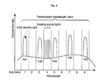
- Fig. 2 shows an example of a wavelength map before the upgrading
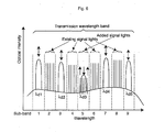
- Fig. 3 shows. an example of a wavelength map during the upgrading
- Fig. 4 shows an example of a wavelength map after the upgrading.
- the horizontal axis expresses sub-bands and the vertical axis expresses optical intensity.
- An optical transmitter 10 outputs a plurality of signal lights and a plurality of ASE dummy lights, each having a different wavelength as shown in Fig. 2, into an optical transmission line 12.
- the signal lights and ASE dummy lights propagated in the optical transmission line 12 enter an optical receiver 14.
- the optical receiver 14 receives and processes the signal lights.
- the transmission wavelength band in the optical transmission line 12 is divided into nine sub-bands and an ASE dummy light is disposed to the odd numbered sub-bands of 1, 3, 5, 7, and 9 while signal lights are disposed to the sub-band 4.
- the optical transmitter 10 before the upgrading comprises a signal light generating unit (existing unit) 20 to generate WDM signal light assigned to the sub-band 4 and an ASE dummy light generating unit 30 to generate ASE dummy lights assigned to the odd numbered sub-bands of 1, 3, 5, 7 and 9.
- the existing unit 20 comprises a plurality of signal light generators 22, each generating a signal light of a different wavelength in the sub-band 4, an arrayed waveguide grating (AWG) 24 as a multiplexer to multiplex output lights from the signal light generators 22, and an optical amplifier 26 to optically amplify an output light, namely WDM signal light, from the AWG 24.
- AWG arrayed waveguide grating
- the ASE dummy light generating unit 30 comprises an ASE dummy light generator 32 to generate ASE dummy lights of dummy wavelengths ⁇ d1 to ⁇ d5 , each wavelength being different from each other, an optical coupler 34 to couple the ASE dummy lights output from the ASE dummy light generators 32, and an optical amplifier 36 to optically amplify an output light from the optical coupler 34.
- the dummy wavelengths ⁇ d1 to ⁇ d5 correspond to the central wavelengths of sub-bands 1, 3, 5, 7, and 9 respectively.
- a signal light generating unit (extension unit) 40 is added to use the sub-band 6 for the signal transmission.
- the configuration of the extension unit 40 is identical to the existing unit 20 except for the signal wavelengths. That is, the extension unit 40 comprises a plurality of signal light generators 42, each generating a signal light of a different wavelength in the sub-band 6, an arrayed waveguide grating (AWG) 44 as a multiplexer to multiplex output lights from the signal light generators 42, and an optical amplifier 46 to optically amplify an output light, i.e. WDM signal light, from the AWG 44.
- AWG arrayed waveguide grating
- an optical coupler 38 couples the output light from the optical amplifier 26 in the existing unit 20 and the output light from the optical amplifier 36 in the ASE dummy light generating unit 30 and outputs the coupled lights into the optical transmission line 12.
- the optical coupler 38 couples the output light from the optical amplifier 26 in the existing unit 20, the output light from the optical amplifier 46 in the extension unit 40, and the output light from the optical amplifier 36 in the ASE dummy light generating unit 30 and outputs the coupled lights into the optical transmission line 12.
- the optical coupler 38 comprises input ports which number corresponds to the number of sub-bands (nine in the embodiment shown in Fig. 2) obtained by dividing the transmission wavelength band in the optical transmission line 12.
- the number of input ports of the optical coupler 38 can be reduced by the number obtained by subtracting 1 from the multiplexed number.
- the multiplexer is considered as a part of the optical coupler 38 and accordingly the required number of input ports becomes equivalent to the number of sub-bands.
- dispersion compensators are appropriately disposed in the optical transmitter 10, optical transmission line 12, and optical receiver 14.
- a large number of optical repeaters might be disposed in the optical transmission line 12. However, since they are unrelated to the present invention, the explanation about those devices is omitted here.
- To equalize a gain profile in an optical transmission line in the case that only a small number of signal wavelengths is used with a gain profile in the case that whole signal wavelengths are used means to equalize the transmission characteristics, more specifically receiving SNR, of each signal wavelength in the case that a small number of signal wavelengths is used with the receiving SNR in the case that whole signal wavelengths are used.
- the optical power of whole ASE dummy lights or the optical power of the ASE dummy lights in the sub-bands 5 and 7 which are adjacent to the sub-band 6 is controlled while the optical power of the signal lights in the sub-band 6 is gradually increased.
- the spectrum analyzer 50 applies its measured content to a control terminal 52.
- the control terminal 52 displays the content measured by the spectrum analyzer 50 on the monitor screen. On the monitor screen, a spectral distribution shown in Fig. 3, for example, is displayed.
- An operator controls the optical power of ASE dummy lights so that the average value of the peak level of existing signal lights maintain the value before the addition of signal lights referring to the spectral distribution displayed on the monitor screen of the control terminal 52.
- the gain of the optical amplifier 36 should be controlled.
- the output light power of corresponding ASE dummy light generator 32 should be controlled.
- the optical power of added signal lights is increased using the optical amplifier 46 in the extension unit 40 until it reaches a predetermined level while the optical power of ASE dummy lights is being controlled.
- the power of whole ASE dummy lights or the optical power of the ASE dummy lights in the adjacent sub-bands should be controlled with the similar operation.
- a signal light unit that corresponds to each sub-band and comprises a similar configuration to the existing signal light generating unit 20 should be connected to the optical coupler 38.
- Fig. 5 shows an example of a wavelength map before the upgrading
- Fig. 6 shows an example of wavelength map during the upgrading
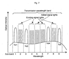
- Fig. 7 shows an example of wavelength map after the upgrading.
- the horizontal axis expresses wavelength or sub-band and the vertical axis expresses optical intensity.
- output lights from four signal light generating units corresponding to the sub-bands of 2, 4, 6, and 8 respectively are connected to the optical coupler 38.
- a signal light generating unit corresponding to the sub-band 5 is provided as an extension unit and connected to the optical coupler 38 in the condition that its optical output is set to OFF state.
- An operator reduces the optical power of the ASE dummy lights in the sub-band 5 while increasing the signal light power in the sub-band 5.
- the operator controls the power of the ASE dummy lights in the sub-bands 1, 3, 7, and 9 so that the average value of the peak level of the existing signal lights in the sub-bands 2, 4, 6, and 8 maintain the value before the addition of signal lights referring to the spectral distribution displayed on the monitor screen of the control terminal 52. It is applicable to set the increasing speed of the signal light power and the decreasing speed of the ASE dummy light power in advance so that both control operations are engaged together to be executed automatically.
- an optical coupler couples the plurality of ASE dummy lights and an optical amplifier is connected to the output of the optical coupler.
- the optical power of the plurality of ASE dummy lights can be controlled in a lump.
Landscapes
- Engineering & Computer Science (AREA)
- Computer Networks & Wireless Communication (AREA)
- Signal Processing (AREA)
- Optical Communication System (AREA)
Applications Claiming Priority (2)
| Application Number | Priority Date | Filing Date | Title |
|---|---|---|---|
| JP2003282807A JP2005051598A (ja) | 2003-07-30 | 2003-07-30 | 光伝送システムのアップグレード方法及び光送信装置 |
| JP2003282807 | 2003-07-30 |
Publications (3)
| Publication Number | Publication Date |
|---|---|
| EP1503533A2 true EP1503533A2 (fr) | 2005-02-02 |
| EP1503533A3 EP1503533A3 (fr) | 2005-09-14 |
| EP1503533B1 EP1503533B1 (fr) | 2007-04-18 |
Family
ID=33535684
Family Applications (1)
| Application Number | Title | Priority Date | Filing Date |
|---|---|---|---|
| EP04017886A Expired - Lifetime EP1503533B1 (fr) | 2003-07-30 | 2004-07-28 | Procédé d'amélioration d'un système de transmission optique à multiplexage en longueurs d'ondes et émetteur optique correspondant |
Country Status (3)
| Country | Link |
|---|---|
| US (1) | US7177540B2 (fr) |
| EP (1) | EP1503533B1 (fr) |
| JP (1) | JP2005051598A (fr) |
Cited By (5)
| Publication number | Priority date | Publication date | Assignee | Title |
|---|---|---|---|---|
| EP1981184A3 (fr) * | 2007-04-10 | 2008-12-10 | Huawei Technologies Co., Ltd. | Appareil et procédé de compensation de gain optique d'un câble optique sous-marin |
| CN102342043A (zh) * | 2009-03-19 | 2012-02-01 | 日本电气株式会社 | 光信号水平调整系统、用于该系统的分析信息和生成控制信号的装置以及分析信息和生成控制信号的方法 |
| CN102342043B (zh) * | 2009-03-19 | 2016-12-14 | 日本电气株式会社 | 光信号水平调整系统、该系统中的信息分析/控制信号生成装置以及信息分析/控制信号生成方法 |
| CN107408985A (zh) * | 2015-03-18 | 2017-11-28 | 日本电气株式会社 | 光传送系统及其分析方法、终端站设备和管理设备 |
| CN111656712A (zh) * | 2018-01-31 | 2020-09-11 | 日本电气株式会社 | 光传输设备、传输系统和传输系统的控制方法 |
Families Citing this family (34)
| Publication number | Priority date | Publication date | Assignee | Title |
|---|---|---|---|---|
| EP1553710A1 (fr) * | 2004-01-08 | 2005-07-13 | Alcatel | Procédé de commande de puissance dans un réseau DWDM par la détermination du facteur Q |
| JP4643645B2 (ja) * | 2004-08-11 | 2011-03-02 | タイコ エレクトロニクス サブシー コミュニケーションズ エルエルシー | 光伝送システムにスペクトル負荷を与えるシステム及び方法 |
| JP2007274482A (ja) * | 2006-03-31 | 2007-10-18 | Fujitsu Ltd | 光伝送装置 |
| JP5076660B2 (ja) | 2007-06-11 | 2012-11-21 | 日本電気株式会社 | 波長多重伝送装置、制御方法及び制御プログラム |
| US20090269058A1 (en) * | 2008-04-28 | 2009-10-29 | Mark Summa | System and Method for Self-Generation of Reference Signals |
| JP5178544B2 (ja) * | 2009-01-16 | 2013-04-10 | 三菱電機株式会社 | 波長多重伝送システム |
| JP5489533B2 (ja) * | 2009-05-20 | 2014-05-14 | 三菱電機株式会社 | 光伝送装置、光波長増設装置および光波長増設方法 |
| CN102687428B (zh) | 2009-10-16 | 2016-01-20 | 日本电气株式会社 | 光分路单元、光通信系统和光复用方法 |
| US8542992B2 (en) * | 2010-02-26 | 2013-09-24 | Fujitsu Limited | System and method for mitigating polarization hole burning |
| US8670664B2 (en) | 2010-02-26 | 2014-03-11 | Fujitsu Limited | System and method for managing the selection of ghost channels for mitigating polarization hole burning |
| US8811822B2 (en) | 2010-02-26 | 2014-08-19 | Fujitsu Limited | System and method for selection of ghost channels for mitigating polarization hole burning |
| JP5866775B2 (ja) * | 2010-02-26 | 2016-02-17 | 富士通株式会社 | 偏波ホールバーニングを軽減させるシステム及び方法 |
| JP5545752B2 (ja) * | 2010-12-20 | 2014-07-09 | 富士通テレコムネットワークス株式会社 | 光パケット交換システム |
| US8971705B2 (en) * | 2011-09-02 | 2015-03-03 | Ciena Corporation | Transient and switching event stabilization of fiber optic transport systems |
| JP6051994B2 (ja) | 2013-03-25 | 2016-12-27 | 富士通株式会社 | 光伝送装置及びダミー光挿入方法 |
| JP6387965B2 (ja) * | 2013-09-24 | 2018-09-12 | 日本電気株式会社 | 伝送装置、伝送システム、伝送方法及びプログラムが記憶された記憶媒体 |
| US9634761B2 (en) * | 2014-04-11 | 2017-04-25 | Alcatel Lucent | Apparatus and method for optical-network monitoring |
| US10419147B2 (en) * | 2014-09-03 | 2019-09-17 | Alcatel Lucent | Optical line loading using variable bandwidth noise |
| US9853762B2 (en) * | 2014-12-04 | 2017-12-26 | Ciena Corporation | Automated provisioning and control of shared optical spectrum in submarine optical networks |
| US20160173202A1 (en) * | 2014-12-16 | 2016-06-16 | Alcatel-Lucent Canada Inc. | Adaptive Noise Loading in Optical Communication Networks |
| WO2016139933A1 (fr) * | 2015-03-04 | 2016-09-09 | 日本電気株式会社 | Dispositif de surveillance de signal optique, appareil de transmission par multiplexage en longueur d'onde optique, et procédé de surveillance de signal optique |
| US9941991B2 (en) * | 2016-08-29 | 2018-04-10 | Huawei Technologies Co., Ltd. | Method and system for controlling spectral occupancy |
| US10298317B2 (en) * | 2017-03-17 | 2019-05-21 | Infinera Corporation | Systems and methods for dynamic spectral shaping in optical communications |
| US11374675B2 (en) * | 2017-06-28 | 2022-06-28 | Huawei Technologies Co., Ltd. | Method and apparatus for modifying channels in an optical medium |
| US11038615B2 (en) | 2018-04-16 | 2021-06-15 | Huawei Technologies Co., Ltd. | Fast connection turn-up with path-based dummy lights |
| US10707958B2 (en) * | 2018-08-31 | 2020-07-07 | Adva Optical Networking Se | Method and apparatus for determining a maximum transmission capacity within an optical network |
| US10547404B1 (en) * | 2018-11-13 | 2020-01-28 | Ciena Corporation | Automatic optical link calibration with channel holders |
| WO2020121716A1 (fr) * | 2018-12-12 | 2020-06-18 | 日本電気株式会社 | Dispositif de transmission optique, dispositif terminal, système de communication optique et procédé de communication optique |
| WO2020158190A1 (fr) * | 2019-01-31 | 2020-08-06 | 日本電気株式会社 | Dispositif de transmission optique, dispositif terminal, système de communication optique et procédé de communication optique |
| US11664891B2 (en) | 2019-03-04 | 2023-05-30 | Nec Corporation | Optical multiplexer/demultiplexer, optical submarine cable system, optical multiplexing/demultiplexing method, and non-transitory computer readable medium |
| WO2021245847A1 (fr) * | 2020-06-03 | 2021-12-09 | 日本電気株式会社 | Dispositif de surveillance de signal optique et procédé de surveillance de signal optique |
| EP3937401B1 (fr) * | 2020-07-07 | 2023-04-12 | ADVA Optical Networking SE | Procédé et dispositif de migration de trafic de données d'un système de transmission wdm optique existant vers un nouveau système de transmission wdm optique |
| US11323175B1 (en) * | 2020-10-28 | 2022-05-03 | Infinera Corporation | Fast system optimization (FSO) with optimally placed recovery tones |
| JP7690759B2 (ja) * | 2021-03-22 | 2025-06-11 | 日本電気株式会社 | 光ネットワーク管理装置、光ネットワークシステム、光ネットワーク管理方法および光ネットワーク管理プログラム |
Family Cites Families (12)
| Publication number | Priority date | Publication date | Assignee | Title |
|---|---|---|---|---|
| JP3821920B2 (ja) * | 1996-09-17 | 2006-09-13 | 富士通株式会社 | 光通信システム |
| JP3875190B2 (ja) * | 2000-07-31 | 2007-01-31 | 三菱電機株式会社 | 波長分割多重光伝送装置 |
| JP4388705B2 (ja) * | 2001-01-31 | 2009-12-24 | 富士通株式会社 | 光増幅器 |
| JP2002353939A (ja) * | 2001-05-25 | 2002-12-06 | Kddi Submarine Cable Systems Inc | 光送信装置 |
| JP2003051786A (ja) * | 2001-08-06 | 2003-02-21 | Fujitsu Ltd | 波長多重光伝送装置 |
| US6944399B2 (en) * | 2001-08-28 | 2005-09-13 | Dorsal Networks, Inc. | Methods of signal substitution for maintenance of amplifier saturation |
| US6907195B2 (en) * | 2001-08-28 | 2005-06-14 | Dorsal Networks, Inc. | Terminals having sub-band substitute signal control in optical communication systems |
| JP3799266B2 (ja) * | 2001-11-15 | 2006-07-19 | 富士通株式会社 | 誘導ブリリュアン散乱を利用した雑音光除去方法、雑音光除去装置および光伝送システム |
| JP2003169037A (ja) | 2001-11-29 | 2003-06-13 | Nec Corp | 波長多重伝送装置 |
| EP1453226B1 (fr) * | 2001-12-03 | 2012-02-01 | Fujitsu Limited | Systeme de communication optique |
| JP2005051596A (ja) * | 2003-07-30 | 2005-02-24 | Kddi Submarine Cable Systems Inc | 光伝送方法及び光送信装置 |
| JP4643645B2 (ja) * | 2004-08-11 | 2011-03-02 | タイコ エレクトロニクス サブシー コミュニケーションズ エルエルシー | 光伝送システムにスペクトル負荷を与えるシステム及び方法 |
-
2003
- 2003-07-30 JP JP2003282807A patent/JP2005051598A/ja active Pending
-
2004
- 2004-07-28 EP EP04017886A patent/EP1503533B1/fr not_active Expired - Lifetime
- 2004-07-29 US US10/903,999 patent/US7177540B2/en not_active Expired - Fee Related
Cited By (13)
| Publication number | Priority date | Publication date | Assignee | Title |
|---|---|---|---|---|
| EP1981184A3 (fr) * | 2007-04-10 | 2008-12-10 | Huawei Technologies Co., Ltd. | Appareil et procédé de compensation de gain optique d'un câble optique sous-marin |
| CN102342043A (zh) * | 2009-03-19 | 2012-02-01 | 日本电气株式会社 | 光信号水平调整系统、用于该系统的分析信息和生成控制信号的装置以及分析信息和生成控制信号的方法 |
| US8798473B2 (en) | 2009-03-19 | 2014-08-05 | Nec Corporation | Optical signal level adjustment system, information analysis/control signal generation apparatus in the same system, and information analysis/control signal generation method |
| CN102342043B (zh) * | 2009-03-19 | 2016-12-14 | 日本电气株式会社 | 光信号水平调整系统、该系统中的信息分析/控制信号生成装置以及信息分析/控制信号生成方法 |
| US10230483B2 (en) | 2015-03-18 | 2019-03-12 | Nec Corporation | Optical transmission system, method for analyzing thereof, terminal station device, and management device |
| EP3273626A4 (fr) * | 2015-03-18 | 2018-12-05 | Nec Corporation | Système de transmission optique, son procédé d'analyse, dispositif de station terminale et dispositif de gestion |
| CN107408985A (zh) * | 2015-03-18 | 2017-11-28 | 日本电气株式会社 | 光传送系统及其分析方法、终端站设备和管理设备 |
| CN107408985B (zh) * | 2015-03-18 | 2020-02-21 | 日本电气株式会社 | 光传送系统及其分析方法、终端站设备和管理设备 |
| US11082144B2 (en) | 2015-03-18 | 2021-08-03 | Nec Corporation | Optical transmission system, method for analyzing thereof, terminal station device, and management device |
| US11451317B2 (en) | 2015-03-18 | 2022-09-20 | Nec Corporation | Optical transmission system, method for analyzing thereof, terminal station device, and management device |
| CN111656712A (zh) * | 2018-01-31 | 2020-09-11 | 日本电气株式会社 | 光传输设备、传输系统和传输系统的控制方法 |
| EP3748881A4 (fr) * | 2018-01-31 | 2021-03-31 | NEC Corporation | Dispositif de transmission optique, système de transmission, et procédé de commande pour système de transmission |
| US11115128B2 (en) | 2018-01-31 | 2021-09-07 | Nec Corporation | Optical transmission device, transmission system, and control method for transmission system |
Also Published As
| Publication number | Publication date |
|---|---|
| US20050024715A1 (en) | 2005-02-03 |
| US7177540B2 (en) | 2007-02-13 |
| JP2005051598A (ja) | 2005-02-24 |
| EP1503533A3 (fr) | 2005-09-14 |
| EP1503533B1 (fr) | 2007-04-18 |
Similar Documents
| Publication | Publication Date | Title |
|---|---|---|
| EP1503533B1 (fr) | Procédé d'amélioration d'un système de transmission optique à multiplexage en longueurs d'ondes et émetteur optique correspondant | |
| US7142785B2 (en) | Light branching/inserting apparatus and light branching apparatus using wavelength selection filter | |
| EP1214760B9 (fr) | Systemes de transmission optique a amplificateurs optiques et procedes d'utilisation associes | |
| US7295782B2 (en) | Control method and optical data transmission path for compensating changes in SRS-induced power exchange | |
| CN1906876B (zh) | 稀疏波分复用光传送系统以及稀疏波分复用光传送方法 | |
| US7200333B2 (en) | Optical communication apparatus, system, and method that properly compensate for chromatic dispersion | |
| EP1746745A2 (fr) | Amplificateur optique avec commande d'une lumière de pompage pour l'amplification raman | |
| EP1909412B1 (fr) | Test de liens optiquement amplifiés à l'aide de signaux de test de multiplexage temporel | |
| JP4083444B2 (ja) | ラマン増幅を利用した光伝送システムおよび光伝送方法 | |
| JP2010226169A (ja) | 光送信装置、光通信方法および光通信システム | |
| US6563978B2 (en) | Optical transmission system and optical coupler/branching filter | |
| JP2003131273A (ja) | ラマン増幅制御方法および光通信システムおよび光増幅装置およびプログラム | |
| US8134775B2 (en) | Raman amplifier with signal modulated before stimulated brillouin scattering occurs | |
| Kato et al. | Whole band wavelength conversion for wideband transmission | |
| US7209501B2 (en) | Multi-wavelength laser source based on two optical laser beat signal and method | |
| JPWO2009022396A1 (ja) | 光波形整形方法および装置 | |
| JP2005051596A (ja) | 光伝送方法及び光送信装置 | |
| US7330302B2 (en) | Optical transmission system | |
| US20250202591A1 (en) | Optical communication system and optical communication method | |
| KR100549779B1 (ko) | 음분산 광섬유를 이용하는 파장분할다중방식 메트로광통신망 |
Legal Events
| Date | Code | Title | Description |
|---|---|---|---|
| PUAI | Public reference made under article 153(3) epc to a published international application that has entered the european phase |
Free format text: ORIGINAL CODE: 0009012 |
|
| AK | Designated contracting states |
Kind code of ref document: A2 Designated state(s): AT BE BG CH CY CZ DE DK EE ES FI FR GB GR HU IE IT LI LU MC NL PL PT RO SE SI SK TR |
|
| AX | Request for extension of the european patent |
Extension state: AL HR LT LV MK |
|
| PUAL | Search report despatched |
Free format text: ORIGINAL CODE: 0009013 |
|
| AK | Designated contracting states |
Kind code of ref document: A3 Designated state(s): AT BE BG CH CY CZ DE DK EE ES FI FR GB GR HU IE IT LI LU MC NL PL PT RO SE SI SK TR |
|
| AX | Request for extension of the european patent |
Extension state: AL HR LT LV MK |
|
| 17P | Request for examination filed |
Effective date: 20060222 |
|
| RAP1 | Party data changed (applicant data changed or rights of an application transferred) |
Owner name: MITSUBISHI DENKI KABUSHIKI KAISHA Owner name: KDDI SUBMARINE CABLE SYSTEMS INC. |
|
| AKX | Designation fees paid |
Designated state(s): FR GB |
|
| REG | Reference to a national code |
Ref country code: DE Ref legal event code: 8566 |
|
| 17Q | First examination report despatched |
Effective date: 20060320 |
|
| RTI1 | Title (correction) |
Free format text: METHOD FOR UPGRADING A WAVELENGTH DIVISION MULTIPLEXING OPTICAL TRANSMISSION SYSTEM AND OPTICAL TRANSMITTER THEREFOR |
|
| GRAP | Despatch of communication of intention to grant a patent |
Free format text: ORIGINAL CODE: EPIDOSNIGR1 |
|
| GRAS | Grant fee paid |
Free format text: ORIGINAL CODE: EPIDOSNIGR3 |
|
| GRAA | (expected) grant |
Free format text: ORIGINAL CODE: 0009210 |
|
| AK | Designated contracting states |
Kind code of ref document: B1 Designated state(s): FR GB |
|
| ET | Fr: translation filed | ||
| PLBE | No opposition filed within time limit |
Free format text: ORIGINAL CODE: 0009261 |
|
| STAA | Information on the status of an ep patent application or granted ep patent |
Free format text: STATUS: NO OPPOSITION FILED WITHIN TIME LIMIT |
|
| 26N | No opposition filed |
Effective date: 20080121 |
|
| PGFP | Annual fee paid to national office [announced via postgrant information from national office to epo] |
Ref country code: FR Payment date: 20100805 Year of fee payment: 7 |
|
| PGFP | Annual fee paid to national office [announced via postgrant information from national office to epo] |
Ref country code: GB Payment date: 20100728 Year of fee payment: 7 |
|
| GBPC | Gb: european patent ceased through non-payment of renewal fee |
Effective date: 20110728 |
|
| REG | Reference to a national code |
Ref country code: FR Ref legal event code: ST Effective date: 20120330 |
|
| PG25 | Lapsed in a contracting state [announced via postgrant information from national office to epo] |
Ref country code: FR Free format text: LAPSE BECAUSE OF NON-PAYMENT OF DUE FEES Effective date: 20110801 |
|
| PG25 | Lapsed in a contracting state [announced via postgrant information from national office to epo] |
Ref country code: GB Free format text: LAPSE BECAUSE OF NON-PAYMENT OF DUE FEES Effective date: 20110728 |