EP1503576A2 - Verfahren und Vorrichtung zur Umsetzung eines grossen Farbtonbereichs - Google Patents
Verfahren und Vorrichtung zur Umsetzung eines grossen Farbtonbereichs Download PDFInfo
- Publication number
- EP1503576A2 EP1503576A2 EP04003524A EP04003524A EP1503576A2 EP 1503576 A2 EP1503576 A2 EP 1503576A2 EP 04003524 A EP04003524 A EP 04003524A EP 04003524 A EP04003524 A EP 04003524A EP 1503576 A2 EP1503576 A2 EP 1503576A2
- Authority
- EP
- European Patent Office
- Prior art keywords
- gamut
- narrow
- printer
- wide
- mapping
- Prior art date
- Legal status (The legal status is an assumption and is not a legal conclusion. Google has not performed a legal analysis and makes no representation as to the accuracy of the status listed.)
- Withdrawn
Links
Images


Classifications
-
- H—ELECTRICITY
- H04—ELECTRIC COMMUNICATION TECHNIQUE
- H04N—PICTORIAL COMMUNICATION, e.g. TELEVISION
- H04N1/00—Scanning, transmission or reproduction of documents or the like, e.g. facsimile transmission; Details thereof
- H04N1/46—Colour picture communication systems
- H04N1/56—Processing of colour picture signals
- H04N1/60—Colour correction or control
- H04N1/6058—Reduction of colour to a range of reproducible colours, e.g. to ink- reproducible colour gamut
Definitions
- the present invention relates to color gamut mapping different size color gamuts for printing.
- color gamut or gamut generally is used to describe the complete range of colors an image contains or a device is able to render. It is sometimes referred to as a color gamut or the gamut color space associated with a printer or screen display device.
- Gamut mapping an image onto a screen or printer generally requires adjusting the colors of the image to fit in the constrained color gamut of the screen or printer.
- the image being displayed does not have a wide range of colors and therefore does not fill or utilize the wider range of colors in the printer gamut or even the screen gamut.
- the colors in an image are outside the narrow color gamut of a displaying device but can be printed on a color printer having a wider gamut.
- wider gamut color printers have grown in popularity as consumers desire to achieve professional or at least "prosumer” quality color printing.
- Newer applications are being created that send wider gamut images directly to these wider gamut printers and other output devices.
- the peer-to-peer color workflow used in these applications is advantageous as the wider printer gamuts are not limited by the intermediary and narrower gamut of a monitor or other display device.
- cameras, palm tops, cell phones, Internet terminals and digital picture frames generate images using wider gamuts in YCC, Adobe RGB, bgRGB, scRGB, CIELAB, e-sRGB or ROMM digital representations.
- These devices are imaging enabled and connected to a printer directly or through a network or Internet connection and do not need to display images using a narrow gamut like sRGB.
- a wide gamut application performs processing on the wide gamut information and then outputs the image data to the printer by gamut mapping between the wide gamut and the printer gamut; narrow gamut sRGB applications process narrow gamut information but instead perform gamut mapping from the narrow gamut to the printer gamut.
- the printed output differs on conventional systems due to the different types of gamut mapping and transformations performed. For example, conventional systems using sRGB cannot accurately represent the numerous dark chromatic colors as they are outside the narrow gamut space of sRGB.
- FIG. 1 is a flowchart diagram of the workflow for an application printing on a wide gamut printer in accordance with one implementation of the present invention
- FIG. 2A and 2B are block diagram representations of a wide gamut, a printer gamut and a narrow gamut in two different color space representations;
- FIG. 3A, 3B, 3C, 3D, 3E are used to visualize the color gamut mapping operation in accordance with one implementation of the present invention.
- FIG. 4 is a flowchart diagram of the operations for gamut mapping using narrow interpolation points and wide interpolation points in accordance with one implementation of the present invention
- FIG. 5 is a flowchart diagram providing further detailed operations for identifying both narrow interpolation points and wide interpolation points in accordance with one implementation of the present invention.
- FIG. 6 is a block diagram of a system used in one implementation of the present invention for performing the apparatus or methods of the present invention.
- the gamut mapping includes receiving a narrow gamut, a wide gamut and a printer gamut for printing on a printer and a predetermined mapping between the narrow gamut and the printer gamut; identifying overlapping areas in the wide gamut, the narrow gamut and the printer gamut; determining when the narrow gamut overlaps one or more areas of the wide gamut; utilizing the narrow gamut values when the determination provides overlapping areas of the narrow gamut and the wide gamut; selecting a wide gamut interpolation point corresponding to the surface of the printer gamut when narrow gamut areas do not overlap the wide gamut according to the determination; selecting a narrow gamut interpolation point by mapping the narrow gamut to the printer gamut based upon a reference color space; and interpolating the narrow gamut interpolation point and the wide gamut interpolation point to expand the narrow gamut values into the printer gamut.
- Gamut mapping systems and methods designed in accordance with implementations of the present invention have at least one or more of the following advantages.
- Recently developed wider gamut spaces are mapped to an entire printer gamut space without adversely affecting the mapping of narrower or smaller gamut spaces to the same printer space.
- Gamut mapping from a wide gamut space like YCC, Adobe RGB, bgRGB, scRGB, CIELAB, e-sRGB or ROMM to a printer gamut space is supported as well as the narrow gamut space to printer gamut space mapping.
- the dominant workflow based on a sRGB narrow gamut smoothly extends into areas of the printer gamut beyond the narrow gamut range.
- the gamut mapping for the sRGB narrow gamut coexists with the gamut mapping between the wider gamuts and a target printer gamut.
- sRGB narrow gamut are combined with a wide gamut colormap (e.g., YCC) to extrapolate a consistent gamut mapping in the printer gamut.
- a popular narrow gamut workflow e.g., sRGB
- FIG. 1 is a flowchart diagram of the workflow operations for an application printing on a wide gamut printer in accordance with one implementation of the present invention.
- Workflow 100 includes image sources 102, a wide gamut application 104, a narrow gamut application 106, a wide gamut image format 108, a narrow gamut image format 110, an expanded narrow gamut mapping component 112 and a wider gamut printer 114 that outputs a printed output 116.
- This example illustrates web pages 118, DVD120, digital camera 122 and scanner 124 producing high quality images compatible with printing from a wide gamut application 104 or a narrow gamut application 106.
- a digital camera 118 may capture images represented in a wide gamut like ROMM and print the image with consistent color rendering through wide gamut application 104 or narrow gamut application 106.
- the wide gamut information is communicated directly to printers and other high quality imaging devices in a peer-to-peer type workflow model.
- This is generally an improvement over more CRT-centric models that limit the image data to the narrow gamut associated with the CRT (e.g., sRGB) rather than the typically larger gamut of the printer.
- workflow 100 supports wide gamut application 104 as a newer gamut color processing format as well as narrow gamut application 106 as the dominant legacy image processing format. Unlike conventional systems, workflow 100 uses implementations of the present invention to generate consistent color printing.
- Implementations of the present invention produce consistent printed results by combining the narrow, wide and printer gamuts together in workflow 100. Accordingly, expanded narrow gamut mapping component 112 uses a dominant existing narrow gamut like sRGB in combination with a wide-gamut to more smoothly extend into any printer gamut not already covered by the narrow gamut. The resulting images can be printed with more consistent results on printer with wider gamut color printing 114 producing printed output 116.
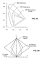
- FIG. 2A and 2B are block diagram representations of a wide gamut, a printer gamut and a narrow gamut in two different representations.
- FIG. 2A illustrates wide gamut 202, printer gamut 204 and narrow gamut 206 superimposed over a CIELAB color space. This representation of the colors illustrates the growing trend to create printers with a wider printer gamut 204 as well as the relative difference between narrow gamut 206 and wider gamut 202.
- FIG. 2B instead illustrates wide gamut 208, printer gamut 210 and narrow gamut (sRGB) 212 in a CIE LCH (Luminosity, Chroma and Hue) color space framework.
- CIE LCH Luminosity, Chroma and Hue
- Color gamut in CIELAB color space can be transformed into CIE LCH color space using transforms well known in the art. This latter illustration not only shows the relative difference in gamut but also the variation in shape of the respective gamut. As will be described later herein, implementations of the present invention combine these gamut sizes and shapes together (i.e., narrow gamut and wide gamut) to perform color gamut mapping and print consistent color images.
- FIG. 3A through FIG. 3E are used to visualize the color gamut mapping operation in accordance with one implementation of the present invention. Operations associated with the gamut mapping illustrated in these diagrams also correspond to subsequent flowchart diagrams.
- a wide gamut 302 is superimposed over a narrow gamut 304 and the LCH color space. Using this color space information, the surface of the wide gamut is clipped to the surface of the narrow gamut as illustrated. For purposes of explanation, point w1 and w2 on the surface of wide gamut 302 are clipped and mapped to points n1 and n2 respectively on the surface of narrow gamut 304.
- a printer gamut 306 is superimposed over narrow gamut 304 and the surface of points resulting from the previous clipping and mapping operation.
- the points in this resulting surface are then translated to the corresponding values in printer gamut 306 according to a reference color space like CIELAB or LCH.
- the resulting translation creates a relationship between points like n1 and n2 on the surface of narrow gamut 304 and points p1 and p2 within printer gamut 306.
- Points p1, p2 and many other points create a surface and a set of narrow gamut interpolation points to be referenced and used subsequently in conjunction with narrow gamut 304.
- FIG. 3C is an illustration of narrow gamut interpolation points p1 and p2 wide gamut interpolation points p1' and p2' along with the resulting surface.
- the chroma of narrow gamut interpolation points p1, p2 and other points on the surface are generally increased until they are on the surface of printer gamut 306.
- the p1', p2' and other points on the resulting surface are considered the wide gamut interpolation points and are also used to interpolate values in color space outside the narrow gamut.
- FIG. 3D is a composite illustration of the narrow, wide and printer gamut along with representative points corresponding to the operations of the present invention.
- the interpolation points resulting from these operations are used to perform gamut mapping when the color values are not in the narrow gamut.
- Color values that fall in the narrow gamut range i.e., the sRGB color space
- FIG. 3E provides a zoomed in view (not-to-scale) illustrating the interpolation points used to interpolate values lying somewhere between the narrow gamut and wide gamut.
- p2 is one narrow gamut interpolation point
- p2' is one wide gamut interpolation point used in accordance with gamut mapping of the present invention. Colors within the narrow gamut are preserved and used while colors outside the narrow gamut are obtained by interpolating between the narrow and wide gamut interpolation points.
- a color falling at position i2 would be analyzed by linear interpolation of the respective interpolation points. Specifically, i2 would be calculated as approximately 1 ⁇ 2 (p2 + p2'); other points outside the narrow gamut would be calculated similarly based on the position of using points in set of interpolation points 318.
- FIG. 4 is a flowchart diagram of the operations for gamut mapping using narrow interpolation points and wide interpolation points in accordance with one implementation of the present invention.
- implementations of the present invention receive a narrow gamut (e.g., sRGB), a printer gamut, a wide gamut for processing and a predetermined mapping between the narrow and printer gamuts (402).
- the areas in a CIELAB or LCH space are compared to determine the one or more areas that the wide gamut, narrow gamut and printer gamut overlap (404).
- the narrow gamut data values are used for lookup table entries in lieu of wide gamut or print gamut values (408).
- values of both the narrow gamut and the wide gamut are used in accordance with the present invention.
- implementations of the present invention select wide gamut interpolation points corresponding to the surface of the printer gamut (410) and narrow gamut interpolation points by mapping points on the narrow gamut surface (412). Details on selecting these interpolation points are described in further detail later herein and in conjunction with FIG. 5.
- the narrow and wide interpolation points are used to linearly interpolate and identify proper corresponding areas in the printer gamut (414).
- the interpolation maintains the hue of the clipped color while increasing the chroma to the printer surface. Lightness of each resulting color is modified to a fractional difference in lightness between the lightness of the clipped value and the original undipped value.
- the color values in the narrow gamut e.g., sRGB
- sRGB are used along with color values resulting from interpolation when doing the gamut mapping. As previously described, this preserves the narrow gamut information while using the wide gamut to print in the printer gamut color space
- Another method is used to extrapolate between the narrow gamut and wide gamut when gamut mapping.
- points on the surface of the wide gamut are also clipped to the surface of the narrow gamut but in CIELAB rather than CIE LCH color space.
- a difference or delta gamut value is computed as between the wide gamut values and the clipped wide gamut values corresponding to the surface of the narrow gamut.
- the delta gamut value is added to the clipped wide gamut value (on the surface of the narrow gamut) to obtain a goal CIELAB value for the mapped color.
- This operation uses the relative difference between the different gamuts thereby preserving the narrow gamut information (e.g., sRGB).
- the goal CIELAB value is then mapped in the printer gamut using one or more different types of gamut clipping as appropriate.
- Many other combinations of clipping and extrapolating are contemplated to preserve the narrow gamut information and perform gamut mapping in the printer gamut color space.
- FIG. 5 is a flowchart diagram providing further details for identifying both narrow interpolation points and wide interpolation points in accordance with one implementation of the present invention.
- points on the surface of the wide gamut are mapped to corresponding points on the surface of narrow gamut using a clipping operation (502).
- the narrow gamut sRGB having independent RGB colors with an RGB range of (0..255, 0..255,0..255) is clipped by rounding each independent color channel to the nearest 0 or 255 values when the input RGB values from the wide gamut are out of range.
- alternate implementations of clipping may operate to preserve a constant hue or clip a gamut intersection toward a gamut centroid, for example.
- the location of the clipped narrow gamut values in the printer gamut are then determined by way of narrow gamut to printer gamut mapping information (504).
- Predetermined gamut mapping information for this transformation locates and maps the narrow gamut surface of points to corresponding points in the printer gamut.
- the narrow gamut interpolation points are set to the resulting printer gamut values from this narrow gamut to printer gamut mapping (506). This portion of the results is used back in FIG. 4 at step 410 where the narrow gamut interpolation points are identified.
- processing continues and the chroma of the narrow gamut interpolation points are increased until the points are on the printer gamut surface (508).
- the wide interpolation points are set to these points along the printer surfaced based upon increasing the chroma values of the narrow interpolation points (510). These resulting values are also used in FIG. 4 at step 412 to identify the wide gamut interpolation points.
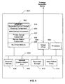
- FIG. 6 is a block diagram of a system 600 used in one implementation for performing methods or implementing an apparatus of the present invention.
- System 600 includes a memory 602 to hold executing programs typically random access memory (RAM) or read-only memory (ROM) such as a flash ROM, an image driver 604 capable of interfacing and driving a display or output device, a processor 606, a program memory 608 for holding drivers or other frequently used programs, a network communication port 610 for data communication, a secondary storage 612 with secondary storage controller, and input/output (I/O) ports 614 also with I/O controller operatively coupled together over a bus 616.
- RAM random access memory
- ROM read-only memory
- I/O input/output
- system 600 can be preprogrammed, in ROM, for example, using field-programmable gate array (FPGA) technology or it can be programmed (and reprogrammed) by loading a program from another source (for example, from a floppy disk, a CD-ROM, or another computer).
- FPGA field-programmable gate array
- system 600 can be implemented using customized application specific integrated circuits (ASICs).
- memory 602 includes an expanded narrow gamut mapping component 618, a wide gamut component 620, a printer gamut component 622, a narrow gamut component 624, and a run-time module 626 that manages system resources used when processing one or more of the above components on system 600.
- Expanded narrow gamut mapping component 618 is designed to identify interpolation points for both the narrow gamut component 624 and wide gamut component 620 and interpolate these points in accordance with the present invention.
- narrow gamut component 624 entries are used for gamut mapping except when the values are outside the narrow gamut range.
- Points in printer gamut component 622 are identified for printing by interpolating between the narrow gamut and the wide gamut. For example, this preserves the narrow gamut information when using the popular sRGB narrow gamut while providing a smooth transition to the wider printer gamuts. The result is more consistent printed color output while exploiting the higher quality print available on newer wider gamut color printers.
- implementations of the invention can be implemented in digital electronic circuitry, or in computer hardware, firmware, software, or in combinations of them.
- Apparatus of the invention can be implemented in a computer program product tangibly embodied in a machine-readable storage device for execution by a programmable processor; and method steps of the invention can be performed by a programmable processor executing a program of instructions to perform functions of the invention by operating on input data and generating output.
- the invention can be implemented advantageously in one or more computer programs that are executable on a programmable system including at least one programmable processor coupled to receive data and instructions from, and to transmit data and instructions to, a data storage system, at least one input device, and at least one output device.
- Each computer program can be implemented in a high-level procedural or object-oriented programming language, or in assembly or machine language if desired; and in any case, the language can be a compiled or interpreted language.
- Suitable processors include, by way of example, both general and special purpose microprocessors. Generally, a processor will receive instructions and data from a read-only memory and/or a random access memory.
- a computer will include one or more mass storage devices for storing data files; such devices include magnetic disks, such as internal hard disks and removable disks; magneto-optical disks; and optical disks.
- Storage devices suitable for tangibly embodying computer program instructions and data include all forms of non-volatile memory, including by way of example semiconductor memory devices, such as EPROM, EEPROM, and flash memory devices; magnetic disks such as internal hard disks and removable disks; magneto-optical disks; and CD-ROM disks. Any of the foregoing can be supplemented by, or incorporated in, ASICs.
Landscapes
- Engineering & Computer Science (AREA)
- Multimedia (AREA)
- Signal Processing (AREA)
- Color Image Communication Systems (AREA)
- Facsimile Image Signal Circuits (AREA)
- Image Processing (AREA)
- Color, Gradation (AREA)
Applications Claiming Priority (2)
| Application Number | Priority Date | Filing Date | Title |
|---|---|---|---|
| US632858 | 2003-07-31 | ||
| US10/632,858 US7474438B2 (en) | 2003-07-31 | 2003-07-31 | Wide gamut mapping method and apparatus |
Publications (2)
| Publication Number | Publication Date |
|---|---|
| EP1503576A2 true EP1503576A2 (de) | 2005-02-02 |
| EP1503576A3 EP1503576A3 (de) | 2006-06-07 |
Family
ID=33541551
Family Applications (1)
| Application Number | Title | Priority Date | Filing Date |
|---|---|---|---|
| EP04003524A Withdrawn EP1503576A3 (de) | 2003-07-31 | 2004-02-17 | Verfahren und Vorrichtung zur Umsetzung eines grossen Farbtonbereichs |
Country Status (3)
| Country | Link |
|---|---|
| US (1) | US7474438B2 (de) |
| EP (1) | EP1503576A3 (de) |
| JP (1) | JP2005057767A (de) |
Cited By (1)
| Publication number | Priority date | Publication date | Assignee | Title |
|---|---|---|---|---|
| EP2541893A1 (de) * | 2011-06-28 | 2013-01-02 | Konica Minolta Laboratory U.S.A., Inc. | Verfahren zur Verarbeitung von Bildern mit hoher dynamischer Bandbreite unter Verwendung von Dynamikkompression für erweiterten RGB-Raum |
Families Citing this family (16)
| Publication number | Priority date | Publication date | Assignee | Title |
|---|---|---|---|---|
| US7965426B2 (en) * | 2005-08-12 | 2011-06-21 | Canon Kabushiki Kaisha | Image processing apparatus and method for performing gamut mapping via device-independent standard color space |
| KR101303874B1 (ko) * | 2006-02-10 | 2013-09-04 | 삼성전자주식회사 | 색역 매핑 장치 및 방법 |
| CA2677956A1 (en) * | 2006-02-28 | 2007-09-07 | Ernest Daniel Miller | Color management of digital files and images for printing |
| KR100843088B1 (ko) * | 2006-08-16 | 2008-07-02 | 삼성전자주식회사 | 광색역 공간의 영상을 출력하는 장치 및 방법 |
| KR100818986B1 (ko) * | 2006-08-18 | 2008-04-04 | 삼성전자주식회사 | 광색역 색 공간을 위한 색 변환 방법 |
| US8068255B2 (en) | 2006-11-17 | 2011-11-29 | Microsoft Corporation | Gamut mapping spectral content to reduce perceptible differences in color appearance |
| JP4853296B2 (ja) * | 2007-01-15 | 2012-01-11 | 富士ゼロックス株式会社 | 色変換装置、色変換方法、色変換プログラム、色変換係数作成装置、色変換係数作成方法、及び色変換係数作成プログラム |
| JP5043513B2 (ja) * | 2007-05-28 | 2012-10-10 | キヤノン株式会社 | 色処理装置および方法 |
| JP4775328B2 (ja) * | 2007-06-07 | 2011-09-21 | 富士ゼロックス株式会社 | 画像処理装置およびプログラム |
| JP2009278538A (ja) * | 2008-05-16 | 2009-11-26 | Ricoh Co Ltd | 画像処理装置、画像処理方法、プログラムおよび記録媒体 |
| US8125685B1 (en) * | 2008-09-30 | 2012-02-28 | Adobe Systems Incorporated | Clipping colors to a gamut surface |
| JP5482073B2 (ja) * | 2009-10-05 | 2014-04-23 | 富士ゼロックス株式会社 | 画像処理装置、画像形成システム、およびプログラム |
| JP5137938B2 (ja) * | 2009-12-22 | 2013-02-06 | キヤノン株式会社 | インクジェット記録装置及びインクジェット記録システム |
| US9621764B2 (en) | 2013-07-31 | 2017-04-11 | Hewlett-Packard Development Company, L.P. | Printer cartridge and memory device containing a compressed color table |
| KR20160059240A (ko) * | 2014-11-18 | 2016-05-26 | 삼성전자주식회사 | 색 재현 영역을 표시하는 방법 및 장치 |
| DK3166795T3 (en) | 2015-05-15 | 2019-02-18 | Hewlett Packard Development Co | PRINTER CARTRIDGES AND MEMORY UNITS CONTAINING COMPRESSED MULTI-DIMENSIONAL COLOR TABLES |
Family Cites Families (25)
| Publication number | Priority date | Publication date | Assignee | Title |
|---|---|---|---|---|
| US5416890A (en) * | 1991-12-11 | 1995-05-16 | Xerox Corporation | Graphical user interface for controlling color gamut clipping |
| JPH07222011A (ja) * | 1994-01-31 | 1995-08-18 | Canon Inc | 色再現範囲表現方法及び画像処理方法及び装置 |
| US6046118A (en) * | 1996-08-02 | 2000-04-04 | E. I. Du Pont De Nemours And Company | Composite sheet material |
| US5892891A (en) * | 1996-11-20 | 1999-04-06 | Xerox Corporation | System for printing color images with extra colorants in addition to primary colorants |
| US6181445B1 (en) * | 1998-03-30 | 2001-01-30 | Seiko Epson Corporation | Device-independent and medium-independent color matching between an input device and an output device |
| JPH11341296A (ja) | 1998-05-28 | 1999-12-10 | Sony Corp | 色域変換方法及び色域変換装置 |
| US6724507B1 (en) * | 1998-07-02 | 2004-04-20 | Fuji Xerox Co., Ltd. | Image processing method and image processing apparatus |
| JP3583630B2 (ja) | 1998-11-30 | 2004-11-04 | 富士通株式会社 | カラーデータ変換方法 |
| JP2000278546A (ja) * | 1999-01-22 | 2000-10-06 | Sony Corp | 画像処理装置及び画像処理方法、色域変換テーブル作成装置及び色域変換テーブル作成方法、画像処理プログラムを記録した記録媒体、並びに色域変換テーブル作成プログラムを記録した記録媒体 |
| US7177465B1 (en) * | 1999-07-16 | 2007-02-13 | Fuji Photo Film Co., Ltd. | Method of compressing/extending color reproducing space, color reproducing method and color reproducing apparatus |
| JP2001292890A (ja) * | 2000-04-11 | 2001-10-23 | Nakahara Sanpodo:Kk | 複数供養壇 |
| JP3830747B2 (ja) * | 2000-10-10 | 2006-10-11 | 三菱電機株式会社 | 色再現域圧縮方法および色再現域圧縮装置 |
| JP2002185804A (ja) | 2000-12-11 | 2002-06-28 | Ricoh Co Ltd | 色変換装置および色変換方法および色変換用パラメータ生成装置および色変換用パラメータ生成方法および画像処理システムおよび記録媒体 |
| JP4223708B2 (ja) | 2001-03-26 | 2009-02-12 | セイコーエプソン株式会社 | 色変換プログラムを記録した媒体、色変換プログラム、色変換テーブルの作成方法、色変換装置および色変換方法 |
| US7355745B2 (en) * | 2001-04-13 | 2008-04-08 | Hewlett Packard | Document-to-printer color gamut matching |
| US7046393B2 (en) * | 2001-04-26 | 2006-05-16 | Hewlett-Packard Development Company, L.P. | Color space transformation with black preservation for open color management |
| JP2003060925A (ja) | 2001-08-14 | 2003-02-28 | Canon Inc | 画像形成システム及びその制御方法 |
| JP3818098B2 (ja) * | 2001-08-17 | 2006-09-06 | ソニー株式会社 | 画像信号処理方法及び画像信号処理装置 |
| JP3797199B2 (ja) * | 2001-11-08 | 2006-07-12 | ソニー株式会社 | 画像記録方法及び画像情報処理装置 |
| KR100416231B1 (ko) | 2001-11-08 | 2004-01-31 | 한국전자통신연구원 | 칼라 디바이스의 선형 색역폭 확장장치 및 그 방법 |
| JP2003153020A (ja) | 2001-11-12 | 2003-05-23 | Canon Inc | カラー処理装置およびその方法 |
| US7233694B2 (en) * | 2002-06-21 | 2007-06-19 | Canon Kabushiki Kaisha | Image capturing apparatus and method, computer program, and computer-readable recording medium therefor |
| KR100467600B1 (ko) * | 2002-07-30 | 2005-01-24 | 삼성전자주식회사 | 컬러 정정 방법 |
| US7233413B2 (en) * | 2002-11-22 | 2007-06-19 | E. I. Du Pont De Nemours And Company | Gamut description and visualization |
| US7411696B2 (en) * | 2003-01-15 | 2008-08-12 | Xerox Corporation | Smooth gray component replacement strategy that utilizes the full device gamut |
-
2003
- 2003-07-31 US US10/632,858 patent/US7474438B2/en not_active Expired - Fee Related
-
2004
- 2004-02-17 EP EP04003524A patent/EP1503576A3/de not_active Withdrawn
- 2004-08-02 JP JP2004225220A patent/JP2005057767A/ja not_active Withdrawn
Non-Patent Citations (1)
| Title |
|---|
| None * |
Cited By (2)
| Publication number | Priority date | Publication date | Assignee | Title |
|---|---|---|---|---|
| EP2541893A1 (de) * | 2011-06-28 | 2013-01-02 | Konica Minolta Laboratory U.S.A., Inc. | Verfahren zur Verarbeitung von Bildern mit hoher dynamischer Bandbreite unter Verwendung von Dynamikkompression für erweiterten RGB-Raum |
| US8576445B2 (en) | 2011-06-28 | 2013-11-05 | Konica Minolta Laboratory U.S.A., Inc. | Method for processing high dynamic range images using tone mapping to extended RGB space |
Also Published As
| Publication number | Publication date |
|---|---|
| US20050024652A1 (en) | 2005-02-03 |
| JP2005057767A (ja) | 2005-03-03 |
| EP1503576A3 (de) | 2006-06-07 |
| US7474438B2 (en) | 2009-01-06 |
Similar Documents
| Publication | Publication Date | Title |
|---|---|---|
| US7474438B2 (en) | Wide gamut mapping method and apparatus | |
| JP5270346B2 (ja) | マルチメディア色管理システム | |
| EP1909486B1 (de) | Verfahren und Vorrichtung zur Durchführung eines Skalenabgleichs zwischen heterogenen Geräten | |
| US7450281B2 (en) | Image processing apparatus and information processing apparatus, and method thereof | |
| US9472162B2 (en) | Method of mapping source colors from a source color gamut into a target color gamut | |
| US7929760B2 (en) | Color processing method and apparatus based on viewing condition | |
| EP2890107A1 (de) | Verfahren zur Zuordnung der Quellfarben von Bildern eines Videoinhalts in einer Zielfarbenskala einer Zielfarbenvorrichtung | |
| JP2010183232A (ja) | 色域変換装置 | |
| JP2005354372A (ja) | 画像記録装置、画像記録方法、画像処理装置、画像処理方法、及び画像処理システム | |
| EP1465408A2 (de) | System und Verfahren zur Erhaltung des Schwarz-Kanals | |
| US20120105678A1 (en) | Image capturing systems and methods utilizing customizable look management | |
| US20080174798A1 (en) | Color-management apparatus and method | |
| US20080013827A1 (en) | Method of Electronic Color Image Saturation Processing | |
| US20040135790A1 (en) | Correcting the color cast of an image | |
| CN107251554A (zh) | 色彩表生成装置、摄像机图像补正/控制装置及其方法 | |
| JP4150490B2 (ja) | 画像処理システムおよび画像処理方法および記録媒体 | |
| US20070053023A1 (en) | Color processing apparatus and its method | |
| US20040061912A1 (en) | Information processing apparatus | |
| JP2003234916A (ja) | 画像処理装置、画像処理方法、印刷装置、画像処理プログラムおよび画像処理プログラムを記録した媒体 | |
| US7227552B1 (en) | Image processing apparatus and method and storage medium | |
| Holm | Integrating New Color Image Processing Techniques with Color Management | |
| JP3854706B2 (ja) | 画像処理装置、方法および記録媒体 | |
| JP2004072758A (ja) | 色処理装置および色処理方法、色処理プログラム | |
| JP2004023650A (ja) | 画像処理装置及び該画像処理装置に用いる画像生成もしくは処理プログラム | |
| JP2005341260A (ja) | 画像処理方法、画像処理プログラムおよび画像処理装置 |
Legal Events
| Date | Code | Title | Description |
|---|---|---|---|
| PUAI | Public reference made under article 153(3) epc to a published international application that has entered the european phase |
Free format text: ORIGINAL CODE: 0009012 |
|
| AK | Designated contracting states |
Kind code of ref document: A2 Designated state(s): AT BE BG CH CY CZ DE DK EE ES FI FR GB GR HU IE IT LI LU MC NL PT RO SE SI SK TR |
|
| AX | Request for extension of the european patent |
Extension state: AL LT LV MK |
|
| PUAL | Search report despatched |
Free format text: ORIGINAL CODE: 0009013 |
|
| AK | Designated contracting states |
Kind code of ref document: A3 Designated state(s): AT BE BG CH CY CZ DE DK EE ES FI FR GB GR HU IE IT LI LU MC NL PT RO SE SI SK TR |
|
| AX | Request for extension of the european patent |
Extension state: AL LT LV MK |
|
| 17P | Request for examination filed |
Effective date: 20061025 |
|
| 17Q | First examination report despatched |
Effective date: 20070111 |
|
| AKX | Designation fees paid |
Designated state(s): DE FR GB |
|
| STAA | Information on the status of an ep patent application or granted ep patent |
Free format text: STATUS: THE APPLICATION IS DEEMED TO BE WITHDRAWN |
|
| 18D | Application deemed to be withdrawn |
Effective date: 20090901 |