EP1504155B1 - Verfahren und vorrichtung zur kontrolle der trockenlinie bei der langsiebpapiermaschine und zur darauf beruhenden steuer- und regelung - Google Patents
Verfahren und vorrichtung zur kontrolle der trockenlinie bei der langsiebpapiermaschine und zur darauf beruhenden steuer- und regelung Download PDFInfo
- Publication number
- EP1504155B1 EP1504155B1 EP03722651A EP03722651A EP1504155B1 EP 1504155 B1 EP1504155 B1 EP 1504155B1 EP 03722651 A EP03722651 A EP 03722651A EP 03722651 A EP03722651 A EP 03722651A EP 1504155 B1 EP1504155 B1 EP 1504155B1
- Authority
- EP
- European Patent Office
- Prior art keywords
- dry line
- paper machine
- wire
- dry
- pulp
- Prior art date
- Legal status (The legal status is an assumption and is not a legal conclusion. Google has not performed a legal analysis and makes no representation as to the accuracy of the status listed.)
- Expired - Lifetime
Links
Images
Classifications
-
- D—TEXTILES; PAPER
- D21—PAPER-MAKING; PRODUCTION OF CELLULOSE
- D21G—CALENDERS; ACCESSORIES FOR PAPER-MAKING MACHINES
- D21G9/00—Other accessories for paper-making machines
- D21G9/0009—Paper-making control systems
- D21G9/0027—Paper-making control systems controlling the forming section
-
- Y—GENERAL TAGGING OF NEW TECHNOLOGICAL DEVELOPMENTS; GENERAL TAGGING OF CROSS-SECTIONAL TECHNOLOGIES SPANNING OVER SEVERAL SECTIONS OF THE IPC; TECHNICAL SUBJECTS COVERED BY FORMER USPC CROSS-REFERENCE ART COLLECTIONS [XRACs] AND DIGESTS
- Y10—TECHNICAL SUBJECTS COVERED BY FORMER USPC
- Y10S—TECHNICAL SUBJECTS COVERED BY FORMER USPC CROSS-REFERENCE ART COLLECTIONS [XRACs] AND DIGESTS
- Y10S162/00—Paper making and fiber liberation
- Y10S162/09—Uses for paper making sludge
- Y10S162/10—Computer control of paper making variables
Definitions
- the subject of the present invention is a method according to the preamble of claim 1 for determining the dry line in a paper machine.
- the invention relates correspondingly to an apparatus for carrying out this method.
- An essential part of the wet end of a Fourdrinier paper machine is the continuously moving plane wire, on which the dilute wood fibre pulp is fed and on which it settles forming a web. A major part of the water contained in the fibre pulp is removed through the holes of the wire.
- a typical dry line exhibits the disappearance of the specularly reflecting water from the pulp surface and the dimming of the pulp surface at a transfer to the later side of this place.
- the change can, at some places, be observed even by naked eye, primarily when a suitably located observer sees the mirror image of the light source only as a partial figure cut by the dry line.
- the machine operators accordingly base their numerous, manual control actions traditionally on their partial and subjective dry line observations of this kind.
- Instrumental methods have been developed earlier, for formation of an image of the dry line, for the whole extent of the latter. Their practical operation requires i.a. that the area of its appearance is illuminated as homogeneously as possible. An optical image of the total area of appearance of the dry line can thereby be formed by a video camera on its detector surface.
- a digital computer By transferring the electrical image signal to a digital computer one may further analyze the image and determine the dry line by means of a program serving this aim.
- the dry line determined by such means can be reproduced by a graphical monitor display or by a printed output and expressed also as a data sequence or by means of average and other characteristic numbers.
- the dry line data can further be transferred to a controller, which may be a program block programmed to act as a controller or a separate device unit, and which controls by feedback an actuator affecting the dry line, such as the lip or lip screws of the head box, or in a feedforward manner actuators existing at a later part of the paper machine.
- a controller which may be a program block programmed to act as a controller or a separate device unit, and which controls by feedback an actuator affecting the dry line, such as the lip or lip screws of the head box, or in a feedforward manner actuators existing at a later part of the paper machine.
- the customary dry line manifests, if expressed by means of properties of the pulp surface, a decrease of the specular reflectivity and an increase of the diffuse reflectivity of the surface, of which the former method (EP 341248) stresses the latter feature and the later one (EP 586458) the former feature.
- the stated methods use, for production of the dry line signal, light of a wide spectrum which does not differ much from the spectrum of the general illumination at the place of their use, the light used for detection of the dry line must be relatively powerful, in order to produce a sufficient signal-to-background ratio.
- An object of the invention is to create a solution, which produces, a primary measurement signal which differs from the background better than those produced by the earlier methods, and through it, detection of the dry line and control signal of the paper machine at an essentially lower electrical power than that needed by them.
- An object is also to present a solution which can be implemented in many such paper machine environments as well, in which the earlier methods are not applicable for structural reasons.
- characteristic to the method according to the invention is that, which is presented in the patent claim 1, while the characteristics of the apparatus according to the invention appear correspondingly from the claim 4.
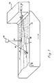
- Figure 1 presents the paper machine's wire part 10, on which the turbulent surface of the pulp coming from the head box 50 calms down, at the border III, to a plane, specularly reflecting water surface.
- the radiation source 20 emits a scanning laser beam A1 which, if hitting the specularly reflecting surface produces the specularly reflected ray A2. If in turn hitting the part after the dry line, the scanning laser beam B 1 produces a weaker, specularly reflected ray B2.
- the detector 30 detects the rays A3 and B3 reflected diffusely by the points of hit.
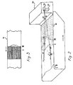
- the alternative structure according to Fig. 2 differs from Fig. 1 only in that the detector 40 is located at or next to the radiation source 20.
- the diffuse reflections or the rays hitting the detector are marked by A4, correspondingly by B4.
- the new invention for production of a dry line signal is based on the use of a light source emitting electromagnetic radiation of a narrow wavelength range or more such radiation components simultaneously, whereby a high signal/background ratio is reached with regard to the background radiation of a wide spectrum.
- Radiation of this kind is produced in practice by using a strongly directing source of laser radiation.
- the radiation emitted by such a source represents typically one wavelength or a narrow wavelength range or a few, separate wavelengths only. Said wavelength may lie in the visible or invisible part of the spectrum.
- the HeNe laser emitting red light of the wavelength 633 nm is an appropriate example of a radiation source which suits to many types of pulps.
- the commercially available laser radiation sources have usually been constructed for emission of unidirectional radiation of a thin cross section.
- a light source of solid state such as a laser
- the source and the detector of reflected, scattered light are permanently located in a measurement head which may be a fixed one or moving in the transversal direction of the machine, and which is close to the web surface and in contact to this.
- this method does not include the distribution of illumination onto a wide, two-dimensional material surface, which would be required by detection of the meandering dry line extending from one side of the pulp to the other side. It is obviously also impossible to bring the device according to the method into contact with pulp in the wet end of the paper machine, and also to locate it into proximity of the humid pulp surface, because of e.g. the condensing humidity evaporated from the pulp.
- Laser is used as the preferable light source in determination of the fibre orientation in the dry end of the paper machine by the method according to the US patent No 5640244.
- the light radiation is thereby pointed in a fixed direction to the surface of the paper, while each radiation source and detector either are permanently installed or traverse together mechanically, in the cross direction of the machine, said determination being based on detection of the reflectively scattered light and usually also on that of light scattered back to different directions, i.e. diffusively.
- This method does neither comprise a distribution of illumination onto a two-dimensional material surface, nor has its use to other monitoring of the humid fibre pulp in the wet end of the paper machine been disclosed.
- Laser radiation obeys the general laws of physical optics. As it hits e.g. the diffusely reflecting pulp surface at the far side of the stated, typical dry line I, it is scattered from it to the space above the wire, especially to the direction of the specular reflexion and directions close to this, but diffusely also to all other directions. From all directions above the wire, the point hit is seen as a spot, which is considerably brighter than its environment. If the beam hits, instead of that, the specularly reflecting water surface preceding the dry line, a part of it determined by the angle of arrival is reflected into direction of the principal reflection, and the other part refracted below the water surface.
- the dry line which indicates the disappearance of free water from the pulp surface, can thus be determined by pointing a laser beam in a low angle to the pulp surface both before and after the dry line, or by scanning the pulp with a laser beam in machine direction and measuring the intensities of the radiation scattered to a separate detector from different points hit.
- a pass-over from a weak, scattered signal to a strong signal indicates thereby the location of a single dry line point, which may be defined more closely as the location of e.g. the average value of the readings before and after the dry line, or as that of their steepest change or as that according to other suitable criterion.
- a change of reflectance in the same direction as that at the dry line I appears again at the dry line II located in the range of the flat suction box. Because of the strong suction by the flat suction box, an essential part of the water left between the fibres is removed here from the pulp on the wire, whereby the reflectively scattered radiation is further decreased and the diffusively scattered radiation increased.
- the increase of intensity of the diffusively scattered radiation and the dry line II corresponding to that can therefore be measured and determined essentially in the same manner as that presented previously about the determination of the dry line I.
- Figure 3 presents, by way of an example, the manner in which the laser beam scans the area of appearance of the dry line I, in both longitudinal and crosswise direction.
- E.g. turning or rotating mirrors such as the galvanometer scanner provided with two, turning mirrors to which the laser beam is directed, can be used to control the laser beam according to the manner described.
- Measured data which is proportional to the scatter is obtained on the points in the area of appearance of the dry line, which are known by means of the known dependencies of the directional angle on voltage and of the known galvanometer/wire geometry, by changing stepwise the control voltages of the mirrors.
- the data may be interpolated into a rectangular coordinate system according to the main directions of the machine, for a computational determination of the dry line and of quantities descriptive of it.
- the stated quantities can be determined in a straightforward manner.
- the laser scanning similarly as the detection of the radiation scattered by its target represent prior art, which is described e.g. in the book "Laser Beam Scanning", Marcel Dekker, Inc. 1985, edited by G.F. Marshall; the book includes also examples of laser scanners produced industrially.
- a suitable location of the laser radiation source 20 is above the centre line of the wire, in such a place, from which the laser beam can be pointed to all parts of the area of appearance of the dry line, in a low angle.
- the source can be located also elsewhere above the level of wire and outside the wire, assuming that the conditions stated in the previous sentence are satisfied.
- the sensor for measurement of radiation scattered by the target may be a photo diode, photo multiplier or other optoelectrical detector, which is sensitive to said radiation. Lens hoods, optics of high lighting capacity and optical filters can also be used, for an added distinction of the signal being measured.
- the detector may be located in a fixed or rotating manner in such a place (see 30, Fig. 1) where the light from all points of the dry line area can reach it. Because the scattered or diffusely reflected radiation is often powerful in directions next to the specularly reflected radiation, it is generally favourable that the direction of measurement of the scattered radiation differs clearly from the direction of the specular reflection.
- the choice of the type and power of the laser and that of the sensitivity of the detector is influenced also by i.a. the weakening of the secondary radiation between the wire and detector, while the thin primary beam may be considered to reach all parts of the dry line area with a practically equal power.
- the stated source contains also information, which deals with reading of information from the object, such as reading of pictures and writings from paper, by means of a laser scanner and sensor.
- information from the object such as reading of pictures and writings from paper
- the dry line area on a pulp web of a breadth of e.g. 5 meters can be scanned and read to the sensor and further on to the computer at a resolution of 256x256 pixels, at intervals of less than 5 secs. Such an interval is sufficiently short for control of the paper machine on the basis of the continuously moving dry line, economizing on the use of the actuators.
- the measured electrical signals which relate to the measured brightness and directional angles or their control voltages are transferred, transforming simultaneously the analog signals to digital data sequences, in real time to a computer, in which the determination of location of each dry line point takes place; the technology needed for these operations is generally known from the past.
- a video camera which is provided, as may be needed, with optical filters and lens hoods, whose photoelectrical detector is preferably an integrated matrix of separate elements on which the image of the dry line area is continuously formed.
- Both the location and brightness data on the object of radiation are hereby obtained through the camera, without a need of feedback information on the direction of the primary beam or on the quantities controlling this. It is hereby also useful to synchronize the speed of the continuous or stepwise scanning of the beam and the reading speed of the detector and possibly also the step length and laser beam diameter with each other in such a manner that the repeatedly determined dry line data can immediately be compared with each other.
- the computer is programmed to also transform the image composed in the camera and in its direction, of the secondary radiation sources, or the corresponding sensor information obtained in the manner described previously, to location and brightness and, further on, to dry line data in the longitudinal and crosswise, rectangular coordinate system of the wire and, if needed, to transform said sensor information also to a coordinate system determined by the image formed e.g. by an obliquely targeted camera.
- the dry line profile obtained which extends from one side of the wire to the other side one may determine further on, as programmed, also the momentary average location of the dry line and, if needed, its mean deviation and other statistical, characteristic numbers, the gliding average location, momentary maximal and minimal readings etc.
- the repeatedly renewed dry line data obtained can be used synchronously for launching of alarms, for feedback control of the dry line and for feedforward control of the paper machine, corresponding to the methods which have been used on the basis of dry line data determined by other practices; references are made to publications and patents stated earlier (J. Berndtson, A.J. Niemi & S. Karine, in Proceedings of 27 th Eucepa Conf., Grenoble, Oct. 11-14, 1999, ATIP, pp. 131-136 and A.J. Niemi & al. 2002).
- the pulp surface may elsewhere exhibit similar borderlines, which describe a change of reflectivity of the surface and which therefore may also be called dry lines.
- Such an other dry line is produced, as at a part of wire which is later than the dry line described previously, the free water left between the fibres or an essential part of it is removed by subjecting the pulp to powerful suction through the flat suction box or boxes located at the end part of the wire, whereby the scattering reflectance of the pulp surface is increased by this water removal process at the same time as the remaining specular reflectivity of the surface is further decreased.
- each dry line as an indicator of an increase of the scattering reflectance and as that of a decrease of the specular reflectance, with the difference that the new method gives prominence to the former one of the features stated last and the method accrding to the stated patent to the latter one of them.
- the scattering reflectivity of the turbulent pulp changes hereby to the specular reflectivity of the pulp's water surface or, in closer terms, the scattering reflectivity of the pulp surface is decreased and its specular reflectivity increased.
- the existence of this phenomenon is observable even by naked eye and for the whole breadth of the wire, i.a. from Fig. 6 of the publication stated previously (A.J. Niemi & S. Karine, 2002).
- this initial border of said water surface is connected to decrease of water in the pulp, it may also be called a dry line, although the change of reflectivity at it has an opposite direction to the change at the two dry lines stated previously.
- This third dry line can obviously be determined as a difference of the responses produced by laser beams, in the same manner as the dry lines stated above.
- the present invention relates accordingly to determination of all such borderlines which appear on the web surface, and which are related to change of reflectivity of the surface and which are directly or indirectly produced by change of amount of water, or by change of moisture, or by that of water proportion or by that of quality of the water/fibre suspension at the surface or in the surface layer of the web.
- the devices for implementation of the presented method are small for their size and therefore easily installed in such a manner that they do not disturb the use or maintenance of the machine.
- the laser beam may scan the dry line area in a low angle from an arbitrary direction, wherefore a suitable direction is found easily.
- the direction of the optical observation may be even the same as that of the primary laser beam (Fig. 2), whereby the equipment causes practically no need of additional space, thus differing from the earlier equipments, which generally required a location of devices at both sides of the wire.
- the new method is able to determine the dry lines also on such ranges of the wire, which were not reached by the illumination or observation according to the earlier methods. It needs less of electrical and lighting energy than the earlier methods and produces a better signal/background ratio than they did.
- a professional who is skilled in technology of papermaking may, on the basis of the invention presented, make conclusions on alternative methods, which are obvious in different paper machine environments.
- One such alternative is the use of laser radiation primarily on the basis of a change of the specularly reflecting component on pulp surface. It is possible e.g. to install, in the manner presented in the EP patent No 586458, at the side of the wire and parallelly to it, a vertical surface which diffuses light and to which the laser beam is directed. The light spot produced emits light to all directions, also onto the pulp surface.
- a camera installed at the other side of the wire and viewing the wire in a low angle, observes in such a case the spot, if this is reflected to it by the specularly reflecting surface of the pulp, i.e.
- the camera may thus form an image sequence, from which the dry line can be determined.
- Other, obvious alternatives are e.g. a simultaneous use of several, scanning laser beams and the spreading of the primary laser beam by a cylindrical lens to a plane surface, which produces onto the pulp surface a light streak which is perpendicular to direction of the scan, or by diffractive optics to a pyramidal or conical beam cluster, in order to speed up the image analysis.
- the methods indicated here and other methods corresponding to them are considered to be, on the basis of the invention, obvious to a professional and therefore to belong to the scope of the invention presented.
Landscapes
- Paper (AREA)
- Investigating Or Analysing Materials By Optical Means (AREA)
- Inspection Of Paper Currency And Valuable Securities (AREA)
- Analysing Materials By The Use Of Radiation (AREA)
- Investigating Materials By The Use Of Optical Means Adapted For Particular Applications (AREA)
- Length Measuring Devices By Optical Means (AREA)
Claims (5)
- Verfahren zur Bestimmung der Trockenlinie in einer Langsieb-Papiermaschine, indem das Material auf dem Sieb (10) in einem bestimmten Winkel bezüglich des Siebs angestraht, das von der Oberfläche des Materials abgesandte elektromagnetische Signal optisch abgelesen, das abgelesene optische Signal in ein elektrisches digitales Signal wiederholt umgewandelt, der Ort der Trockenlinie als die Grenzlinie zwischen den zwei Teilen der Materialoberfläche auf der Grundlage der vom digitalen Signal übertragenen Daten über das Helligkeitsniveau bestimmt wird und die darauf basierenden Steuerungen bestimmt und die entsprechenden Signale in die die Papiermaschine steuernden Stellorgane übertragen werden, dadurch gekennzeichnet, dass verschiedene Teile des Siebes im Erscheinungsbereich der Trockenlinie mit einem von einer Laser-Strahlungsquelle (20) erzeugten Strahlenbündel angestrahlt werden, das einer engen Frequenzbereich oder mehreren engen Frequenzbereichen entspricht, dass die von der diffusen Reflexion des Strahlenbündels produzierte Strahlung mit Hilfe eines optoelektrischen Detektors (30, 40) in einer Richtung, die sich von der Richtung der spiegelnden Reflexion bezüglich der Richtung der Anstrahlung unterscheidet, beobachtet wird, dass der sich über der Trockenlinie erstreckende Bereich observiert wird und dass der Ort der Trockenlinie mit Hilfe der beobachteten, von beiden Seiten der Trockenlinie ausgestrahlten, sich voneinander unterscheidenden Signale bestimmt wird.
- Verfahren nach dem Anspruch 1, dadurch gekennzeichnet, dass der Erscheinungsbereich der Trockenlinie mit dem von der Laser-Strahlungsquelle erzeugten Strahlenbündel abgetastet wird.
- Verfahren nach dem Anspruch 2, dadurch gekennzeichnet, dass die Steuerungen synchronisch mit dem Abtasten des Erscheinungsbereiches der Trockenlinie wiederholt bestimmt werden.
- Vorrichtung zur Bestimmung einer Trockenlinie in einer Langsieb-Papiermaschine mit einer Lichtquelle (2) zum Anstrahlen des Materials auf dem Sieb (10) in einer ausgewählten Richtung, einem Detektor (30, 40) zur Beobachtung eines elektromagnetischen Signals, das das Material auf dem Sieb infolge der Anstrahlung ausstrahlt, Komponenten zur Verarbeitung der Signale und Steuerungskomponenten zur Weiterverarbeitung des gemessenen, von dem Detektor produzierten Signals und zur Steuerung der Stellorgane der Papiermaschine auf dieser Grundlage, dadurch gekennzeichnet, dass die Vorrichtung eine Laser- Strahlungsquelle (2) zum wiederholten Abtasten des Erscheinungsbereichs der Trockenlinie auf der Stoffoberfläche, der sich auf dem Sieb (10) der Papiermaschine befindet, mit einem Laser-Strahlenbündel, Komponenten zur Bestimmung des in einem speziellen Zeitpunkt vom Strahlenbündel getroffenen Teils der Stoffoberfläche als ein elektrisches Signal, einen Sensor (30, 40) zur Detektion der Intensität des den Sensor treffenden, durch die Stoffoberfläche diffusiv reflektierten Teils des Strahlenbündels als ein elektrisches Signal, Komponenten zur Umwandlung des elektrischen Signals in wiederholt erneuerten digitalen Signale und zur Übertragung dieser Signale und einen digitalen Computer zum Empfangen und zur Verarbeitung der digitalen Signale, ausgestattet mit Programmen zur Bestimmung der Trockenlinie und der diesbezüglichen Grössen auf der Grundlage der von den digitalen Signalen vermittelten Daten über das Helligkeitsniveau und zur Ausgabe der Trockenlinie und der diesbezüglichen Signale und Grössen und zu deren Übertragung in Alarmanlagen und Steuerungsvorrichtungen und Stellorgane der Papiermaschine aufweist.
- Verwendung eines abtastenden Laser-Strahls zur Überwachung der Trockenlinie in einer Langsieb-Papiermaschine.
Applications Claiming Priority (3)
| Application Number | Priority Date | Filing Date | Title |
|---|---|---|---|
| FI20020890 | 2002-05-10 | ||
| FI20020890A FI20020890A7 (fi) | 2002-05-10 | 2002-05-10 | Menetelmä ja laitteisto vesirajan määrittämiseksi ja vesirajaan perustuvaksi ohjaamiseksi Fourdrinier-paperikoneessa |
| PCT/FI2003/000361 WO2003095739A1 (en) | 2002-05-10 | 2003-05-09 | Method and apparatus for monitoring of the dry line in a fou drinier paper machine and for control based thereupon |
Publications (2)
| Publication Number | Publication Date |
|---|---|
| EP1504155A1 EP1504155A1 (de) | 2005-02-09 |
| EP1504155B1 true EP1504155B1 (de) | 2007-01-24 |
Family
ID=8563920
Family Applications (1)
| Application Number | Title | Priority Date | Filing Date |
|---|---|---|---|
| EP03722651A Expired - Lifetime EP1504155B1 (de) | 2002-05-10 | 2003-05-09 | Verfahren und vorrichtung zur kontrolle der trockenlinie bei der langsiebpapiermaschine und zur darauf beruhenden steuer- und regelung |
Country Status (8)
| Country | Link |
|---|---|
| US (1) | US7318882B2 (de) |
| EP (1) | EP1504155B1 (de) |
| AT (1) | ATE352662T1 (de) |
| AU (1) | AU2003229820A1 (de) |
| CA (1) | CA2483877A1 (de) |
| DE (1) | DE60311451T2 (de) |
| FI (1) | FI20020890A7 (de) |
| WO (1) | WO2003095739A1 (de) |
Families Citing this family (7)
| Publication number | Priority date | Publication date | Assignee | Title |
|---|---|---|---|---|
| DE10333977A1 (de) * | 2003-07-25 | 2005-02-10 | Voith Paper Patent Gmbh | Stoffauflauf |
| AT505797B1 (de) * | 2007-09-28 | 2010-03-15 | Mondi Business Paper Services | Verfahren und vorrichtung zum bestimmen einer strömung sowie verwendung hiefür |
| DE102008040688A1 (de) * | 2008-07-24 | 2010-01-28 | Voith Patent Gmbh | Verfahren zur Optimierung der Energiebilanz in Formiereinheiten in Maschinen zur Herstellung von Faserstoffbahnen und Formiereinheit |
| RU2733102C2 (ru) | 2016-11-23 | 2020-09-29 | Айбиэс Оф Америка | Система контроля бумагоделательной машины |
| FI12430U1 (fi) * | 2019-02-04 | 2019-07-15 | Procemex Oy Ltd | Valvontajärjestelmä paperi- tai kartonkikoneen märkäpään massan aktiivisuuden mittaamiseksi |
| US11920299B2 (en) | 2020-03-06 | 2024-03-05 | Ibs Of America | Formation detection system and a process of controlling |
| AU2022299328A1 (en) * | 2021-06-25 | 2024-02-01 | Kimberly-Clark Worldwide, Inc. | Process and system for reorienting fibers in a foam forming process |
Family Cites Families (7)
| Publication number | Priority date | Publication date | Assignee | Title |
|---|---|---|---|---|
| CA1014638A (en) | 1974-04-16 | 1977-07-26 | Domtar Limited | Measuring the surface roughness of a moving sheet material |
| US4500968A (en) * | 1982-06-29 | 1985-02-19 | Domtar Inc. | Paper machine wet line control |
| FI75887C (fi) * | 1986-12-30 | 1991-03-06 | Antti Johannes Niemi | Foerfarande och apparatur foer kontroll av torrlinjen pao planvirapappersmaskin. |
| FI88182C (fi) * | 1991-05-23 | 1993-04-13 | Antti Johannes Niemi | Foerfarande och anordning foer kontroll av torrlinjen och foer pao torrlinjen baserad reglering i en planvirapappersmaskin |
| USH1616H (en) * | 1994-05-31 | 1996-12-03 | Minnesota Mining And Manufacturing Company | Web inspection system having enhanced video signal preprocessing |
| US5492601A (en) * | 1994-07-29 | 1996-02-20 | Wangner Systems Corporation | Laser apparatus and method for monitoring the de-watering of stock on papermaking machines |
| US6053040A (en) * | 1998-08-03 | 2000-04-25 | Callender; Anne | System for the detection and control of paper machine profiles |
-
2002
- 2002-05-10 FI FI20020890A patent/FI20020890A7/fi not_active Application Discontinuation
-
2003
- 2003-05-09 WO PCT/FI2003/000361 patent/WO2003095739A1/en not_active Ceased
- 2003-05-09 EP EP03722651A patent/EP1504155B1/de not_active Expired - Lifetime
- 2003-05-09 DE DE60311451T patent/DE60311451T2/de not_active Expired - Fee Related
- 2003-05-09 AT AT03722651T patent/ATE352662T1/de not_active IP Right Cessation
- 2003-05-09 AU AU2003229820A patent/AU2003229820A1/en not_active Abandoned
- 2003-05-09 US US10/513,733 patent/US7318882B2/en not_active Expired - Fee Related
- 2003-05-09 CA CA002483877A patent/CA2483877A1/en not_active Abandoned
Also Published As
| Publication number | Publication date |
|---|---|
| ATE352662T1 (de) | 2007-02-15 |
| CA2483877A1 (en) | 2003-11-20 |
| US20050139339A1 (en) | 2005-06-30 |
| EP1504155A1 (de) | 2005-02-09 |
| DE60311451T2 (de) | 2007-11-08 |
| WO2003095739A1 (en) | 2003-11-20 |
| US7318882B2 (en) | 2008-01-15 |
| FI20020890A0 (fi) | 2002-05-10 |
| FI20020890A7 (fi) | 2003-11-11 |
| DE60311451D1 (de) | 2007-03-15 |
| AU2003229820A1 (en) | 2003-11-11 |
Similar Documents
| Publication | Publication Date | Title |
|---|---|---|
| US4931657A (en) | On-line texture sensing | |
| US4966455A (en) | Real time mottle measuring device and method | |
| AU606022B2 (en) | Method and apparatus for analyzing the formation of a web of material via generating a formation index | |
| EP2198272B1 (de) | Mikroglanzmessung auf papier und pappe | |
| JPH02501836A (ja) | 長網抄紙機のワイヤー上の乾燥ラインを制御するための方法及び装置 | |
| US7155356B2 (en) | Quality and condition monitoring based on spectrum separating measurement | |
| JPH05509136A (ja) | ウェブのケン縮周波数測定方法及び装置 | |
| EP1504155B1 (de) | Verfahren und vorrichtung zur kontrolle der trockenlinie bei der langsiebpapiermaschine und zur darauf beruhenden steuer- und regelung | |
| EP2914954B1 (de) | Verfahren und vorrichtung zur glanzmessung | |
| JP3119875B2 (ja) | 長網抄紙機におけるドライラインの制御のため又は該ドライラインに基づいた制御のための方法及び装置 | |
| US7101461B2 (en) | Method and apparatus for imaging a paper web | |
| WO2008034954A2 (en) | A method and a device for the measurement of properties of a moving web | |
| EP2103924A1 (de) | Optisches Verfahren und Messvorrichtung für eine Fasern beinhaltende Bahn | |
| Raunio | Quality characterization of tissue and newsprint paper based on image measurements; possibilities of on-line imaging | |
| GB2144218A (en) | Observing streaks in paper | |
| Berndtson et al. | Automatic observation of the dry line in paper machine | |
| CA1310128C (en) | On-line texture sensing | |
| Abidi et al. | Depth Measurement of Moving Slurry at the Wet End of a Paper Machine |
Legal Events
| Date | Code | Title | Description |
|---|---|---|---|
| PUAI | Public reference made under article 153(3) epc to a published international application that has entered the european phase |
Free format text: ORIGINAL CODE: 0009012 |
|
| 17P | Request for examination filed |
Effective date: 20041027 |
|
| AK | Designated contracting states |
Kind code of ref document: A1 Designated state(s): AT BE BG CH CY CZ DE DK EE ES FI FR GB GR HU IE IT LI LU MC NL PT RO SE SI SK TR |
|
| AX | Request for extension of the european patent |
Extension state: AL LT LV MK |
|
| DAX | Request for extension of the european patent (deleted) | ||
| RTI1 | Title (correction) |
Free format text: METHOD AND APPARATUS FOR MONITORING OF THE DRY LINE IN A FOURDRINIER PAPER MACHINE AND FOR CONTROL BASED THEREUPON |
|
| GRAP | Despatch of communication of intention to grant a patent |
Free format text: ORIGINAL CODE: EPIDOSNIGR1 |
|
| GRAS | Grant fee paid |
Free format text: ORIGINAL CODE: EPIDOSNIGR3 |
|
| GRAA | (expected) grant |
Free format text: ORIGINAL CODE: 0009210 |
|
| AK | Designated contracting states |
Kind code of ref document: B1 Designated state(s): AT BE BG CH CY CZ DE DK EE ES FI FR GB GR HU IE IT LI LU MC NL PT RO SE SI SK TR |
|
| PG25 | Lapsed in a contracting state [announced via postgrant information from national office to epo] |
Ref country code: DK Free format text: LAPSE BECAUSE OF FAILURE TO SUBMIT A TRANSLATION OF THE DESCRIPTION OR TO PAY THE FEE WITHIN THE PRESCRIBED TIME-LIMIT Effective date: 20070124 Ref country code: NL Free format text: LAPSE BECAUSE OF FAILURE TO SUBMIT A TRANSLATION OF THE DESCRIPTION OR TO PAY THE FEE WITHIN THE PRESCRIBED TIME-LIMIT Effective date: 20070124 Ref country code: SI Free format text: LAPSE BECAUSE OF FAILURE TO SUBMIT A TRANSLATION OF THE DESCRIPTION OR TO PAY THE FEE WITHIN THE PRESCRIBED TIME-LIMIT Effective date: 20070124 |
|
| REG | Reference to a national code |
Ref country code: GB Ref legal event code: FG4D |
|
| REG | Reference to a national code |
Ref country code: CH Ref legal event code: EP |
|
| REG | Reference to a national code |
Ref country code: IE Ref legal event code: FG4D |
|
| REF | Corresponds to: |
Ref document number: 60311451 Country of ref document: DE Date of ref document: 20070315 Kind code of ref document: P |
|
| PG25 | Lapsed in a contracting state [announced via postgrant information from national office to epo] |
Ref country code: BG Free format text: LAPSE BECAUSE OF EXPIRATION OF PROTECTION Effective date: 20070425 |
|
| PG25 | Lapsed in a contracting state [announced via postgrant information from national office to epo] |
Ref country code: ES Free format text: LAPSE BECAUSE OF FAILURE TO SUBMIT A TRANSLATION OF THE DESCRIPTION OR TO PAY THE FEE WITHIN THE PRESCRIBED TIME-LIMIT Effective date: 20070505 |
|
| REG | Reference to a national code |
Ref country code: SE Ref legal event code: TRGR |
|
| REG | Reference to a national code |
Ref country code: CH Ref legal event code: NV Representative=s name: HEPP, WENGER & RYFFEL AG |
|
| PG25 | Lapsed in a contracting state [announced via postgrant information from national office to epo] |
Ref country code: PT Free format text: LAPSE BECAUSE OF FAILURE TO SUBMIT A TRANSLATION OF THE DESCRIPTION OR TO PAY THE FEE WITHIN THE PRESCRIBED TIME-LIMIT Effective date: 20070625 |
|
| NLV1 | Nl: lapsed or annulled due to failure to fulfill the requirements of art. 29p and 29m of the patents act | ||
| ET | Fr: translation filed | ||
| PG25 | Lapsed in a contracting state [announced via postgrant information from national office to epo] |
Ref country code: SK Free format text: LAPSE BECAUSE OF FAILURE TO SUBMIT A TRANSLATION OF THE DESCRIPTION OR TO PAY THE FEE WITHIN THE PRESCRIBED TIME-LIMIT Effective date: 20070124 |
|
| PLBE | No opposition filed within time limit |
Free format text: ORIGINAL CODE: 0009261 |
|
| STAA | Information on the status of an ep patent application or granted ep patent |
Free format text: STATUS: NO OPPOSITION FILED WITHIN TIME LIMIT |
|
| 26N | No opposition filed |
Effective date: 20071025 |
|
| PG25 | Lapsed in a contracting state [announced via postgrant information from national office to epo] |
Ref country code: CZ Free format text: LAPSE BECAUSE OF FAILURE TO SUBMIT A TRANSLATION OF THE DESCRIPTION OR TO PAY THE FEE WITHIN THE PRESCRIBED TIME-LIMIT Effective date: 20070124 Ref country code: RO Free format text: LAPSE BECAUSE OF FAILURE TO SUBMIT A TRANSLATION OF THE DESCRIPTION OR TO PAY THE FEE WITHIN THE PRESCRIBED TIME-LIMIT Effective date: 20070124 Ref country code: BE Free format text: LAPSE BECAUSE OF FAILURE TO SUBMIT A TRANSLATION OF THE DESCRIPTION OR TO PAY THE FEE WITHIN THE PRESCRIBED TIME-LIMIT Effective date: 20070124 |
|
| PG25 | Lapsed in a contracting state [announced via postgrant information from national office to epo] |
Ref country code: MC Free format text: LAPSE BECAUSE OF NON-PAYMENT OF DUE FEES Effective date: 20070531 |
|
| PG25 | Lapsed in a contracting state [announced via postgrant information from national office to epo] |
Ref country code: GR Free format text: LAPSE BECAUSE OF FAILURE TO SUBMIT A TRANSLATION OF THE DESCRIPTION OR TO PAY THE FEE WITHIN THE PRESCRIBED TIME-LIMIT Effective date: 20070425 Ref country code: IT Free format text: LAPSE BECAUSE OF FAILURE TO SUBMIT A TRANSLATION OF THE DESCRIPTION OR TO PAY THE FEE WITHIN THE PRESCRIBED TIME-LIMIT Effective date: 20070124 |
|
| PG25 | Lapsed in a contracting state [announced via postgrant information from national office to epo] |
Ref country code: IE Free format text: LAPSE BECAUSE OF NON-PAYMENT OF DUE FEES Effective date: 20070509 |
|
| PGFP | Annual fee paid to national office [announced via postgrant information from national office to epo] |
Ref country code: CH Payment date: 20080514 Year of fee payment: 6 Ref country code: DE Payment date: 20080522 Year of fee payment: 6 |
|
| PGFP | Annual fee paid to national office [announced via postgrant information from national office to epo] |
Ref country code: AT Payment date: 20080522 Year of fee payment: 6 |
|
| PGFP | Annual fee paid to national office [announced via postgrant information from national office to epo] |
Ref country code: FI Payment date: 20080522 Year of fee payment: 6 |
|
| PGFP | Annual fee paid to national office [announced via postgrant information from national office to epo] |
Ref country code: SE Payment date: 20080520 Year of fee payment: 6 |
|
| PGFP | Annual fee paid to national office [announced via postgrant information from national office to epo] |
Ref country code: GB Payment date: 20080522 Year of fee payment: 6 |
|
| PG25 | Lapsed in a contracting state [announced via postgrant information from national office to epo] |
Ref country code: EE Free format text: LAPSE BECAUSE OF FAILURE TO SUBMIT A TRANSLATION OF THE DESCRIPTION OR TO PAY THE FEE WITHIN THE PRESCRIBED TIME-LIMIT Effective date: 20070124 |
|
| PG25 | Lapsed in a contracting state [announced via postgrant information from national office to epo] |
Ref country code: CY Free format text: LAPSE BECAUSE OF FAILURE TO SUBMIT A TRANSLATION OF THE DESCRIPTION OR TO PAY THE FEE WITHIN THE PRESCRIBED TIME-LIMIT Effective date: 20070124 |
|
| PG25 | Lapsed in a contracting state [announced via postgrant information from national office to epo] |
Ref country code: LU Free format text: LAPSE BECAUSE OF NON-PAYMENT OF DUE FEES Effective date: 20070509 |
|
| PG25 | Lapsed in a contracting state [announced via postgrant information from national office to epo] |
Ref country code: HU Free format text: LAPSE BECAUSE OF FAILURE TO SUBMIT A TRANSLATION OF THE DESCRIPTION OR TO PAY THE FEE WITHIN THE PRESCRIBED TIME-LIMIT Effective date: 20070725 Ref country code: TR Free format text: LAPSE BECAUSE OF FAILURE TO SUBMIT A TRANSLATION OF THE DESCRIPTION OR TO PAY THE FEE WITHIN THE PRESCRIBED TIME-LIMIT Effective date: 20070124 |
|
| REG | Reference to a national code |
Ref country code: CH Ref legal event code: PL |
|
| GBPC | Gb: european patent ceased through non-payment of renewal fee |
Effective date: 20090509 |
|
| PG25 | Lapsed in a contracting state [announced via postgrant information from national office to epo] |
Ref country code: FI Free format text: LAPSE BECAUSE OF NON-PAYMENT OF DUE FEES Effective date: 20090509 Ref country code: LI Free format text: LAPSE BECAUSE OF NON-PAYMENT OF DUE FEES Effective date: 20090531 Ref country code: CH Free format text: LAPSE BECAUSE OF NON-PAYMENT OF DUE FEES Effective date: 20090531 Ref country code: AT Free format text: LAPSE BECAUSE OF NON-PAYMENT OF DUE FEES Effective date: 20090509 |
|
| REG | Reference to a national code |
Ref country code: FR Ref legal event code: ST Effective date: 20100129 |
|
| PG25 | Lapsed in a contracting state [announced via postgrant information from national office to epo] |
Ref country code: FR Free format text: LAPSE BECAUSE OF NON-PAYMENT OF DUE FEES Effective date: 20090602 |
|
| PGFP | Annual fee paid to national office [announced via postgrant information from national office to epo] |
Ref country code: FR Payment date: 20080430 Year of fee payment: 6 |
|
| PG25 | Lapsed in a contracting state [announced via postgrant information from national office to epo] |
Ref country code: GB Free format text: LAPSE BECAUSE OF NON-PAYMENT OF DUE FEES Effective date: 20090509 |
|
| PG25 | Lapsed in a contracting state [announced via postgrant information from national office to epo] |
Ref country code: DE Free format text: LAPSE BECAUSE OF NON-PAYMENT OF DUE FEES Effective date: 20091201 |
|
| PG25 | Lapsed in a contracting state [announced via postgrant information from national office to epo] |
Ref country code: SE Free format text: LAPSE BECAUSE OF NON-PAYMENT OF DUE FEES Effective date: 20090510 |