EP1504285B1 - Procede et dispositif permettant de mesurer la distance de visibilite a l'aide de systemes de capteurs d'images - Google Patents
Procede et dispositif permettant de mesurer la distance de visibilite a l'aide de systemes de capteurs d'images Download PDFInfo
- Publication number
- EP1504285B1 EP1504285B1 EP03722234A EP03722234A EP1504285B1 EP 1504285 B1 EP1504285 B1 EP 1504285B1 EP 03722234 A EP03722234 A EP 03722234A EP 03722234 A EP03722234 A EP 03722234A EP 1504285 B1 EP1504285 B1 EP 1504285B1
- Authority
- EP
- European Patent Office
- Prior art keywords
- distance
- image sensor
- image
- range
- visual range
- Prior art date
- Legal status (The legal status is an assumption and is not a legal conclusion. Google has not performed a legal analysis and makes no representation as to the accuracy of the status listed.)
- Expired - Lifetime
Links
Images


Classifications
-
- G—PHYSICS
- G01—MEASURING; TESTING
- G01S—RADIO DIRECTION-FINDING; RADIO NAVIGATION; DETERMINING DISTANCE OR VELOCITY BY USE OF RADIO WAVES; LOCATING OR PRESENCE-DETECTING BY USE OF THE REFLECTION OR RERADIATION OF RADIO WAVES; ANALOGOUS ARRANGEMENTS USING OTHER WAVES
- G01S5/00—Position-fixing by co-ordinating two or more direction or position line determinations; Position-fixing by co-ordinating two or more distance determinations
- G01S5/16—Position-fixing by co-ordinating two or more direction or position line determinations; Position-fixing by co-ordinating two or more distance determinations using electromagnetic waves other than radio waves
-
- G—PHYSICS
- G01—MEASURING; TESTING
- G01S—RADIO DIRECTION-FINDING; RADIO NAVIGATION; DETERMINING DISTANCE OR VELOCITY BY USE OF RADIO WAVES; LOCATING OR PRESENCE-DETECTING BY USE OF THE REFLECTION OR RERADIATION OF RADIO WAVES; ANALOGOUS ARRANGEMENTS USING OTHER WAVES
- G01S11/00—Systems for determining distance or velocity not using reflection or reradiation
- G01S11/12—Systems for determining distance or velocity not using reflection or reradiation using electromagnetic waves other than radio waves
-
- G—PHYSICS
- G01—MEASURING; TESTING
- G01S—RADIO DIRECTION-FINDING; RADIO NAVIGATION; DETERMINING DISTANCE OR VELOCITY BY USE OF RADIO WAVES; LOCATING OR PRESENCE-DETECTING BY USE OF THE REFLECTION OR RERADIATION OF RADIO WAVES; ANALOGOUS ARRANGEMENTS USING OTHER WAVES
- G01S3/00—Direction-finders for determining the direction from which infrasonic, sonic, ultrasonic or electromagnetic waves, or particle emission, not having a directional significance, are being received
- G01S3/78—Direction-finders for determining the direction from which infrasonic, sonic, ultrasonic or electromagnetic waves, or particle emission, not having a directional significance, are being received using electromagnetic waves other than radio waves
- G01S3/782—Systems for determining direction or deviation from predetermined direction
- G01S3/783—Systems for determining direction or deviation from predetermined direction using amplitude comparison of signals derived from static detectors or detector systems
- G01S3/784—Systems for determining direction or deviation from predetermined direction using amplitude comparison of signals derived from static detectors or detector systems using a mosaic of detectors
Definitions
- the invention relates to a method and a device for visibility measurement with image sensor systems, comprising at least two image sensors.
- a transmitter emits radiation and the backscattered portions are detected by a receiver and used to calculate the visibility.
- This procedure does not capture information about the lighting conditions of the scene and the contrasts of the objects.
- the perception of sight by humans is decisively determined by these parameters. This method is therefore unsuitable for applications in which information about the range of sight perceived by a human is needed.
- the German patent application DE 199 28 915 A1 discloses a method for determining the range of vision in the field of vision in front of a vehicle with at least one video sensor, the range of sight being taken to be the measured distance of an object whose measured contrast is still sufficiently recognizable to the human eye.
- Pomerleau D " Visibility estimation from a moving vehicle using the RALPH vision system "Intelligent Transportation System, 1997, ITSC '97., IEEE Conference on Boston, MA, USA, 9-12 Nov. 1997
- a method for estimating the visibility emerges. From the JP 631887741 a method for visibility determination is known, based on the bright-dark contrast of a known measurement object, the visibility is determined.
- the method of the present invention extends the functionality of image sensor systems consisting of at least two image sensors to determine the visibility. This is particularly advantageous in motor vehicles in which image sensor systems, in particular with two image sensors, are used to assist the driver in driver assistance systems. The installation of an additional device in the motor vehicle to determine the visibility is no longer necessary.
- the method allows the measurement of the visibility in moving and stationary image sensor systems. In motor vehicles, it is thus possible to determine the range of vision in all states of motion, especially when the vehicle is stationary.
- the determination of the visibility can be done in an advantageous manner with static and moving objects.
- the determination of the visibility in the use of this invention in motor vehicles in any movement conditions of the objects of the environment of the motor vehicle is possible.
- the method described here for determining the visibility takes into account the illumination of the scene.
- the method can be used in all applications in which a size of the visual range corresponding to human perception is needed.
- the visibility is calculated by arithmetic averaging of at least one single-vision distance, which consists of the average contrasts of two different distance ranges is calculated.
- This method is advantageously suitable for calculating the visibility with low computing power of the evaluation unit used.
- Advantageous is the calculation of the visibility by forming an exponential regression of the average contrasts over the distance.
- the preprocessing of the image sensor signals is advantageous. For example, in situations in which only objects of similar size are within the field of vision of the image sensors, the attenuation of the small-scale contrasts of distant objects by the optical properties of the image sensors may lead to an underestimation of the visibility. By pre-processing of the image sensor signals, in particular by a high-pass filtering, this can be prevented.
- an improvement of the image quality such as the elimination of image noise, can be achieved.
- the range of vision calculated from the image sensor signals can be used in subsequent systems.
- driver assistance systems in motor vehicles for example, an optical, acoustic and / or haptic warning of the driver is possible if a maximum speed derived from the visibility conditions is exceeded.
- the involvement of fog lights and / or the dipped beam in motor vehicles when falling below a minimum visibility is conceivable.
- FIG. 1 shows a block diagram of the device, consisting of an image sensor system with an image sensor 11 and a second image sensor 12, two image sensor signal lines 13 and 14, an evaluation unit 15, an output signal line 16 and a subsequent system 17th
- CCD or CMOS cameras can be used as image sensors. Both image sensors are arranged to image the same scene, but at a slightly different viewing angle.
- the image sensors transmit images of the observed scene to the evaluation unit 15.
- Die Evaluation unit 15 generates a signal of the measured value of the visibility on the output signal line 16. This output signal is transmitted electrically, digitally, acoustically and / or visually for display, information and / or storage to at least one subsequent system 17.
- the evaluation unit 15 consists of several in FIG. 2 illustrated modules 23, 24, 25, 26 and 27, which are configured in the preferred embodiment as programs of at least one microprocessor.
- the method is based on a statistical property of natural scenes, according to which the probability of occurrence of an object type is independent of its distance from the image sensor system.
- the property of objects i will use that their object contrast c i , defined as the contrast measured at distance 0, is statistically independent of the position of the object relative to the image sensor system.
- the mean object contrast c is thus statistically independent of the distance from the image sensor system.
- FIG. 2 schematically shows a flowchart for performing the method.
- the image sensor signals 21 and 22 of the signal lines 13 and 14 are supplied to the preprocessing modules 23 and 24.
- module 25 a distance and contrast measurement is performed.
- objects which are completely within the field of vision of both image sensors are detected by means of image processing by means of image segmentation.
- the distance of the object to the image sensor system is determined.
- a particularly suitable option for distance measurement are block-based stereo methods.
- the distance of the objects is measured by the correlation of image blocks along the epipolar in both images. From the relative displacement of the image blocks in both images, the distance of the object from the image sensor system can be calculated since the distance is inversely proportional to the displacement of the image blocks.
- the contrast of the objects is determined.
- the contrast is calculated over the magnitude integral of an edge filter over the image block.
- Conceivable are other known methods of image processing for calculating the contrast over an image detail, such as the calculation of the standard deviation and the variance of the gray values within an image block.
- the method assigns a distance value to each detected contrast value. These value pairs thus obtained are passed as object characteristics to the subsequent module 26 for further processing.
- Module 26 calculates the average contrast in each range of distances. For this purpose the distance is divided into distance ranges. The distance ranges are characterized in the preferred embodiment by the same width ⁇ x.
- the width of the distance ranges it is possible to adjust the width of the distance ranges depending on various parameters, such as time, distance and / or the state of motion of the image sensor system.
- the object characteristics determined in module 25 are assigned to the distance ranges.
- the classification is performed on the basis of the distance parameter.
- the average contrast is calculated by averaging according to the formula (3).
- the formation of the average contrast is based on object characteristics, which were determined within a time window before the calculation time.
- the time window should be chosen so that the visibility within the window does not change significantly.
- the average contrasts of each range of distances are passed to the following module 27 for calculating the visibility. To calculate the visibility, two calculation variants are possible.
- the visibility is formed by arithmetic averaging of at least one single view.
- the individual visual ranges for example D ( x 3 , x 4 ), are formed from average contrast values of two different distances, here x 3 and x 4 , according to formula (5).
- the range of vision may be over an exponential regression, in FIG. 3 are plotted as a regression curve 31.
- the output signal 28, which is a measure of the visibility, is transmitted via the signal line 16 in FIG FIG. 1 passed to the subsequent systems 17.
- FIG. 3 shows the average contrast C ( x ) objects in the same distance range as a function of the distance x.
- the width of a distance range ⁇ x is shown.
- the preprocessing modules 23 and 24 can also be used for example to improve the image quality, to eliminate interference, contrast enhancement and / or edge sharpening.
- the determined visibility is suitably forwarded to at least one subsequent system 17. It is conceivable, for example, an adaptation of at least one system due to the visibility and / or a shutdown or switching on at least one system when leaving an adjustable value range of visibility.
- One possible application is in driver assistance systems in motor vehicles.
- an optical, acoustic and / or haptic warning of the driver when exceeding a derived from the visibility maximum speed is conceivable.
- the method is suitable for switching below a minimum visibility of the fog lights and / or dipped headlights in motor vehicles.
- the method can be used for switching off an on an image sensor system based distance warning system in motor vehicles when a minimum visibility is undercut.
- the described method and the device are not limited to the application of image sensor systems which consist of two image sensors in the motor vehicle.
- the visibility can be formed from two image sensor signals.
- the measurement error of the calculated visibility can be reduced.
- the only requirement is that the image sensors used record the same scene.
- the described procedure with the corresponding Characteristics are used outside the automotive technology.
- the use in image sensor systems for monitoring traffic areas is conceivable.
- the method for automatically adapting the display of the maximum permitted speed to the visibility conditions can be used and / or used to construct a traffic warning system for foggers.
Landscapes
- Physics & Mathematics (AREA)
- Electromagnetism (AREA)
- Engineering & Computer Science (AREA)
- General Physics & Mathematics (AREA)
- Radar, Positioning & Navigation (AREA)
- Remote Sensing (AREA)
- Measurement Of Optical Distance (AREA)
- Length Measuring Devices By Optical Means (AREA)
- Traffic Control Systems (AREA)
Claims (16)
- Procédé de mesure de la distance de visibilité à l'aide de systèmes de capteurs d'images selon lequel- on détermine une grandeur à partir des signaux de capteur d'images, représentant le contraste de l'image prise ou d'un extrait de l'image,- le système de capteurs d'images se compose d'au moins deux capteurs d'images (11, 12) qui prennent pratiquement la même scène,- en outre, à partir des signaux de capteurs d'images, on détermine une grandeur représentant la distance par rapport à l'objet de la prise de vues ou de l'extrait de l'image prise, et, en fonction des grandeurs déterminées, on définit la distance de visibilité (D),caractérisé en ce qu'
on calcule la distance de visibilité (D) en fonction des contrastes moyensC (x) pour au moins deux plages de distances x1 et x2 selon la formule suivante :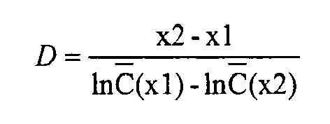
C (x) étant obtenu à partir des contrastes de plusieurs objets qui se trouvent dans une plage de distances x1 ou x2. - Procédé selon la revendication 1,
caractérisé en ce que
le système de capteurs d'images se compose de deux capteurs d'images. - Procédé selon l'une des revendications précédentes,
caractérisé par
les étapes suivantes :- reconnaissance d'objets dans la zone d'image de deux capteurs d'images,- détermination de la distance des objets reconnus par rapport au système de capteurs d'images,- détermination du contraste des objets reconnus,- détermination des données caractéristiques des objets, à savoir la distance et le contraste,- calcul de la distance de visibilité en fonction des données caractéristiques des objets. - Procédé selon la revendication 3,
caractérisé en ce que
le traitement des données caractéristiques d'objets, déterminés, se fait selon les étapes suivantes :- association de la distance et du contraste d'un objet, à une paire de valeurs,- classification des paires de valeurs des objets en fonction de la distance et de la répartition des plages de distances,- calcul du contraste moyen dans chaque plage de distances. - Procédé selon la revendication 4,
caractérisé en ce que
la largeur de la plage de distances est la même dans chaque plage de distances. - Procédé selon la revendication 4,
caractérisé en ce que
la largeur d'au moins une plage de distances est adaptée en fonction du temps, de la distance et/ou de l'état de mouvement du système de capteurs d'images. - Procédé selon l'une des revendications précédentes,
caractérisé en ce qu'
on calcule la distance à partir du décalage relatif de deux blocs correspondants d'un objet dans les images qui se correspondent dans le temps pour deux capteurs d'images. - Procédé selon l'une des revendications précédentes,
caractérisé en ce que
l'on forme le contraste d'un objet dans l'image ou dans l'extrait d'image par l'intégrale de l'amplitude à l'aide d'un filtre à arêtes sur un segment sélectionné de l'image ou des deux images fournies par deux capteurs d'images. - Procédé selon la revendication 3,
caractérisé en ce qu'
à partir des valeurs moyennes de contraste de chaque fois deux plages de distances, différentes par rapport à au moins une plage de distances, on calcule au moins une distance de visibilité individuelle. - Procédé selon la revendication 9,
caractérisé en ce que
l'on forme la distance de visibilité en formant la valeur moyenne arithmétique consécutive d'au moins une distance de visibilité seule. - Procédé selon la revendication 3,
caractérisé en ce que
l'on calcule la distance de visibilité par une régression exponentielle des contrastes moyens en fonction de la distance. - Procédé selon l'une des revendications précédentes,
caractérisé en ce qu'
on prépare les signaux de capteur d'images. - Procédé selon l'une des revendications précédentes,
caractérisé en ce que
l'on utilise la distance de visibilité calculée à partir des signaux de capteur d'images pour adapter au moins un système suivant et/ou en quittant une plage de valeurs réglées de la distance de visibilité, on coupe ou on branche au moins un système. - Procédé selon l'une des revendications précédentes,
caractérisé en ce que
les systèmes de capteurs d'images équipent un véhicule automobile. - Dispositif de mesure de la distance de visibilité (D) à l'aide de système de capteurs d'images comportant au moins deux capteurs d'images (11, 12) qui prennent pratiquement la même scène, une unité d'exploitation (15) calculant la distance de visibilité (D) à partir d'au moins deux signaux de capteurs d'images et générant un signal de sortie comme valeur de mesure, ce signal étant une mesure de la distance de visibilité (D),
caractérisé en ce que
l'unité d'exploitation (15) comporte un module (27),
le module (27) recevant les contrastes moyensC (x) d'au moins deux plages de distances x1 et x2 pour calculer la distance de visibilité (D),
le contraste moyenC (x) étant formé à partir des contrastes de plusieurs objets se trouvant dans une plage de distances x1 ou x2,
la distance de visibilité (D) se calculant selon la formule :
- Dispositif selon l'une des revendications précédentes,
caractérisé en ce que
le système de capteurs d'images équipe un véhicule automobile.
Applications Claiming Priority (3)
| Application Number | Priority Date | Filing Date | Title |
|---|---|---|---|
| DE10219788A DE10219788C1 (de) | 2002-05-03 | 2002-05-03 | Verfahren und Vorrichtung zur Sichtweitenmessung mit Bildsensorsystemen |
| DE10219788 | 2002-05-03 | ||
| PCT/DE2003/001017 WO2003093864A1 (fr) | 2002-05-03 | 2003-03-27 | Procede et dispositif permettant de mesurer la distance de visibilite a l'aide de systemes de capteurs d'images |
Publications (2)
| Publication Number | Publication Date |
|---|---|
| EP1504285A1 EP1504285A1 (fr) | 2005-02-09 |
| EP1504285B1 true EP1504285B1 (fr) | 2008-11-12 |
Family
ID=29225015
Family Applications (1)
| Application Number | Title | Priority Date | Filing Date |
|---|---|---|---|
| EP03722234A Expired - Lifetime EP1504285B1 (fr) | 2002-05-03 | 2003-03-27 | Procede et dispositif permettant de mesurer la distance de visibilite a l'aide de systemes de capteurs d'images |
Country Status (4)
| Country | Link |
|---|---|
| US (1) | US20050231725A1 (fr) |
| EP (1) | EP1504285B1 (fr) |
| DE (1) | DE10219788C1 (fr) |
| WO (1) | WO2003093864A1 (fr) |
Families Citing this family (13)
| Publication number | Priority date | Publication date | Assignee | Title |
|---|---|---|---|---|
| US7270229B2 (en) * | 2004-11-05 | 2007-09-18 | New England Machinery, Inc. | Container unscrambler system having adjustable track and method |
| DE102004061998A1 (de) | 2004-12-23 | 2006-07-06 | Robert Bosch Gmbh | Stereokamera für ein Kraftfahrzeug |
| DE102006005231A1 (de) * | 2006-02-02 | 2007-08-16 | Optotransmitter-Umweltschutz-Technologie E.V. | Entfernungsbestimmung, vorzugsweise zur Sichtweitenbestimmung |
| FR2902556B1 (fr) * | 2006-06-15 | 2008-08-15 | Valeo Vision Sa | Procede de determination d'une distance de visibilite pour un conducteur d'un vehicule. |
| DE102008007347A1 (de) | 2008-02-04 | 2009-08-06 | Robert Bosch Gmbh | Vorrichtung und Verfahren zum Bestimmen der Position eines anderen Verkehrsteilnehmers |
| DE102008001679A1 (de) | 2008-05-09 | 2009-11-12 | Robert Bosch Gmbh | Verfahren und Vorrichtung zur Verarbeitung von aufgenommenen Bildinformationen aus einem Fahrzeug |
| DE102009011866A1 (de) | 2009-03-05 | 2010-09-09 | Volkswagen Ag | Verfahren und Vorrichtung zum Bestimmen einer Sichtweite für ein Fahrzeug |
| DE102009003110A1 (de) | 2009-05-14 | 2010-11-18 | Robert Bosch Gmbh | Bildverarbeitungsverfahren zur Bestimmung von Tiefeninformation aus wenigstens zwei mittels eines Stereokamerasystems aufgenommenen Eingangsbildern |
| DE112010001879A5 (de) | 2009-07-06 | 2012-10-11 | Conti Temic Microelectronic Gmbh | Optisches Modul zur gleichzeitigen Fokussierung auf zwei Sichtbereiche |
| JP5944405B2 (ja) | 2010-11-30 | 2016-07-05 | コンティ テミック マイクロエレクトロニック ゲゼルシャフト ミット ベシュレンクテル ハフツングConti Temic microelectronic GmbH | カメラ及び照明による窓ガラス上の雨滴の検出 |
| DE102011103302A1 (de) | 2011-06-03 | 2012-12-06 | Conti Temic Microelectronic Gmbh | Kamerasystem für ein Fahrzeug |
| DE102011056051A1 (de) | 2011-12-05 | 2013-06-06 | Conti Temic Microelectronic Gmbh | Verfahren zur Auswertung von Bilddaten einer Fahrzeugkamera unter Berücksichtigung von Informationen über Regen |
| DE102012103873A1 (de) | 2012-05-03 | 2013-11-21 | Conti Temic Microelectronic Gmbh | Detektion von Regentropfen auf einer Scheibe mittels einer Kamera und Beleuchtung |
Citations (1)
| Publication number | Priority date | Publication date | Assignee | Title |
|---|---|---|---|---|
| JPS63188741A (ja) * | 1987-02-02 | 1988-08-04 | Hokkaido Kaihatsukiyoku Doboku Shikenjo | 視程計測装置 |
Family Cites Families (8)
| Publication number | Priority date | Publication date | Assignee | Title |
|---|---|---|---|---|
| FI63299C (fi) * | 1980-03-27 | 1983-05-10 | Elevator Gmbh | Foerfarande foer att raekna pao staellet uppstannande objekt |
| FR2721400B1 (fr) * | 1994-06-16 | 1996-09-13 | Valeo Vision | Procédé et dispositif de détection de brouillard ou de fumée, notamment pour véhicule automobile. |
| EP0691534B1 (fr) * | 1994-07-06 | 2001-12-12 | Volkswagen Aktiengesellschaft | Procédé de détermination de la visibilité, en particulier pour le déplacement d'un véhicule |
| EP0879158B1 (fr) * | 1996-02-13 | 1999-07-28 | Marquardt GmbH | Detecteur optique |
| JP4391624B2 (ja) * | 1999-06-16 | 2009-12-24 | 本田技研工業株式会社 | 物体認識装置 |
| DE19928915A1 (de) * | 1999-06-24 | 2001-01-11 | Bosch Gmbh Robert | Verfahren zur Sichtweitenbestimmung |
| DE10034461A1 (de) * | 2000-07-15 | 2002-01-31 | Bosch Gmbh Robert | Verfahren zur Sichtweitenbestimmung |
| US6859804B2 (en) * | 2002-06-11 | 2005-02-22 | The Regents Of The University Of California | Using histograms to introduce randomization in the generation of ensembles of decision trees |
-
2002
- 2002-05-03 DE DE10219788A patent/DE10219788C1/de not_active Expired - Fee Related
-
2003
- 2003-03-27 EP EP03722234A patent/EP1504285B1/fr not_active Expired - Lifetime
- 2003-03-27 WO PCT/DE2003/001017 patent/WO2003093864A1/fr not_active Ceased
- 2003-03-27 US US10/513,197 patent/US20050231725A1/en not_active Abandoned
Patent Citations (1)
| Publication number | Priority date | Publication date | Assignee | Title |
|---|---|---|---|---|
| JPS63188741A (ja) * | 1987-02-02 | 1988-08-04 | Hokkaido Kaihatsukiyoku Doboku Shikenjo | 視程計測装置 |
Also Published As
| Publication number | Publication date |
|---|---|
| DE10219788C1 (de) | 2003-11-13 |
| EP1504285A1 (fr) | 2005-02-09 |
| WO2003093864A1 (fr) | 2003-11-13 |
| US20050231725A1 (en) | 2005-10-20 |
Similar Documents
| Publication | Publication Date | Title |
|---|---|---|
| DE60032973T2 (de) | Stereo-Fahrzeugüberwachungsgerät mit Fehlersicherheits-Funktion | |
| EP1468401B1 (fr) | Procede et dispositif de detection d'obstacles a la visibilite dans le cas de systemes de detection d'images | |
| DE102006020192B4 (de) | Vorrichtung und Verfahren zum Vorhersagen von Kollision | |
| EP1053140B1 (fr) | Procede pour detecter des objets se trouvant sur une plaque transparente et dispositif correspondant | |
| WO2019174682A1 (fr) | Procédé et dispositif de détection et d'évaluation des états de voie de circulation et des influences environnementales météorologiques | |
| EP1330132B1 (fr) | Méthode et dispositif de détection d'occlusions dans des systèmes de capteurs d'images | |
| EP1504285B1 (fr) | Procede et dispositif permettant de mesurer la distance de visibilite a l'aide de systemes de capteurs d'images | |
| WO2022128014A1 (fr) | Correction d'images d'un système de caméra panoramique en conditions de pluie, sous une lumière incidente et en cas de salissure | |
| DE10303046A1 (de) | Verfahren und Vorrichtung zur quantitativen Abschätzung der Sichtweite in Fahrzeugen | |
| EP1303768B1 (fr) | Procede pour determiner la distance de visibilite | |
| DE112008001384T5 (de) | Verfahren zur Verschmutzungserkennung bei einer TOF-Distanzbildkamera | |
| WO2022128013A1 (fr) | Correction d'images à partir d'une caméra en cas de pluie, de lumière incidente et de contamination | |
| WO2012152268A2 (fr) | Détection redondante d'objets pour des systèmes d'aide à la conduite | |
| DE102004046101B4 (de) | Verfahren, Sicherheitsvorrichtung und Verwendung der Sicherheitsvorrichtung zur Früherkennung von Kraftfahrzeugkollisionen | |
| DE102011105074A1 (de) | Verfahren und Vorrichtung zur Bestimmung einer Sichtweite für ein Fahrzeug | |
| WO2010099847A1 (fr) | Procédé et dispositif de détermination d'une portée de visibilité pour un véhicule | |
| DE102017219056A1 (de) | Verfahren und Vorrichtung zum Detektieren zumindest eines verdeckten Objekts im Straßenverkehr für ein Fahrzeug unter Verwendung eines passiven Fahrzeugsensors | |
| DE102005056647A1 (de) | Fahrzeugumgebungsüberwachungsvorrichtung | |
| DE102005056665A1 (de) | Fahrzeugumgebungsüberwachungsvorrichtung | |
| EP2060109A1 (fr) | Procédé et dispositif pour la détection de pixels défectueux d'un capteur d'image, de préférence dans un système d'assistance de conducteur | |
| DE102016208199A1 (de) | Fahrerassistenzsystem mit einer kamera mit verstellmechanismus | |
| DE102006004770B4 (de) | Verfahren zur bildgestützten Erkennung von Fahrzeugen im Umfeld eines Sraßenfahrzeugs | |
| DE112022001328T5 (de) | Bildverarbeitungsvorrichtung und bildverarbeitungsverfahren | |
| WO2020083716A1 (fr) | Système de détection de pluie comprenant un capteur d'environnement servant à détecter point par point un environnement d'un véhicule en particulier avec un capteur d'environnement lidar | |
| DE102009042476A1 (de) | Bestimmung von Zuständen in der Umgebung eines Kraftfahrzeugs mittels einer Stereokamera |
Legal Events
| Date | Code | Title | Description |
|---|---|---|---|
| PUAI | Public reference made under article 153(3) epc to a published international application that has entered the european phase |
Free format text: ORIGINAL CODE: 0009012 |
|
| 17P | Request for examination filed |
Effective date: 20041203 |
|
| AK | Designated contracting states |
Kind code of ref document: A1 Designated state(s): AT BE BG CH CY CZ DE DK EE ES FI FR GB GR HU IE IT LI LU MC NL PT RO SE SI SK TR |
|
| RBV | Designated contracting states (corrected) |
Designated state(s): DE FR GB IT |
|
| GRAP | Despatch of communication of intention to grant a patent |
Free format text: ORIGINAL CODE: EPIDOSNIGR1 |
|
| GRAS | Grant fee paid |
Free format text: ORIGINAL CODE: EPIDOSNIGR3 |
|
| GRAA | (expected) grant |
Free format text: ORIGINAL CODE: 0009210 |
|
| AK | Designated contracting states |
Kind code of ref document: B1 Designated state(s): FR GB IT |
|
| REG | Reference to a national code |
Ref country code: GB Ref legal event code: FG4D Free format text: NOT ENGLISH |
|
| PLBE | No opposition filed within time limit |
Free format text: ORIGINAL CODE: 0009261 |
|
| STAA | Information on the status of an ep patent application or granted ep patent |
Free format text: STATUS: NO OPPOSITION FILED WITHIN TIME LIMIT |
|
| 26N | No opposition filed |
Effective date: 20090813 |
|
| GBPC | Gb: european patent ceased through non-payment of renewal fee |
Effective date: 20090327 |
|
| REG | Reference to a national code |
Ref country code: FR Ref legal event code: ST Effective date: 20091130 |
|
| PG25 | Lapsed in a contracting state [announced via postgrant information from national office to epo] |
Ref country code: GB Free format text: LAPSE BECAUSE OF NON-PAYMENT OF DUE FEES Effective date: 20090327 Ref country code: FR Free format text: LAPSE BECAUSE OF NON-PAYMENT OF DUE FEES Effective date: 20091123 |
|
| PG25 | Lapsed in a contracting state [announced via postgrant information from national office to epo] |
Ref country code: IT Free format text: LAPSE BECAUSE OF NON-PAYMENT OF DUE FEES Effective date: 20090327 |