EP1504802A1 - Dispositif de transport sous vide avec un système de filtre à plusieurs étages - Google Patents
Dispositif de transport sous vide avec un système de filtre à plusieurs étages Download PDFInfo
- Publication number
- EP1504802A1 EP1504802A1 EP04017271A EP04017271A EP1504802A1 EP 1504802 A1 EP1504802 A1 EP 1504802A1 EP 04017271 A EP04017271 A EP 04017271A EP 04017271 A EP04017271 A EP 04017271A EP 1504802 A1 EP1504802 A1 EP 1504802A1
- Authority
- EP
- European Patent Office
- Prior art keywords
- filter
- adapter
- conveying device
- vacuum
- external
- Prior art date
- Legal status (The legal status is an assumption and is not a legal conclusion. Google has not performed a legal analysis and makes no representation as to the accuracy of the status listed.)
- Granted
Links
- 239000012065 filter cake Substances 0.000 claims description 8
- 238000007789 sealing Methods 0.000 claims description 8
- 238000004140 cleaning Methods 0.000 claims description 7
- 125000006850 spacer group Chemical group 0.000 claims description 6
- 238000007664 blowing Methods 0.000 claims description 4
- 238000011144 upstream manufacturing Methods 0.000 claims description 4
- 238000009530 blood pressure measurement Methods 0.000 claims description 3
- 238000000034 method Methods 0.000 claims description 3
- 239000000463 material Substances 0.000 abstract description 14
- 239000000843 powder Substances 0.000 abstract description 2
- 230000008602 contraction Effects 0.000 abstract 1
- 239000007789 gas Substances 0.000 description 7
- 239000012528 membrane Substances 0.000 description 5
- 238000003466 welding Methods 0.000 description 4
- 239000004033 plastic Substances 0.000 description 3
- 229920003023 plastic Polymers 0.000 description 3
- 230000015572 biosynthetic process Effects 0.000 description 2
- 238000005755 formation reaction Methods 0.000 description 2
- 238000009434 installation Methods 0.000 description 2
- 238000005259 measurement Methods 0.000 description 2
- 239000002184 metal Substances 0.000 description 2
- 229910052751 metal Inorganic materials 0.000 description 2
- 150000002739 metals Chemical class 0.000 description 2
- 239000002245 particle Substances 0.000 description 2
- 239000011148 porous material Substances 0.000 description 2
- 230000032258 transport Effects 0.000 description 2
- 229920000544 Gore-Tex Polymers 0.000 description 1
- 239000004809 Teflon Substances 0.000 description 1
- 229920006362 Teflon® Polymers 0.000 description 1
- 238000004026 adhesive bonding Methods 0.000 description 1
- 238000004887 air purification Methods 0.000 description 1
- 239000000919 ceramic Substances 0.000 description 1
- 239000011248 coating agent Substances 0.000 description 1
- 238000000576 coating method Methods 0.000 description 1
- 230000003247 decreasing effect Effects 0.000 description 1
- 238000010586 diagram Methods 0.000 description 1
- -1 dusts Substances 0.000 description 1
- 238000005516 engineering process Methods 0.000 description 1
- 230000007613 environmental effect Effects 0.000 description 1
- 239000004744 fabric Substances 0.000 description 1
- 238000005429 filling process Methods 0.000 description 1
- 238000001914 filtration Methods 0.000 description 1
- 239000010419 fine particle Substances 0.000 description 1
- 239000008187 granular material Substances 0.000 description 1
- 239000000383 hazardous chemical Substances 0.000 description 1
- 239000011261 inert gas Substances 0.000 description 1
- 238000003780 insertion Methods 0.000 description 1
- 230000037431 insertion Effects 0.000 description 1
- 230000002093 peripheral effect Effects 0.000 description 1
- 229920000728 polyester Polymers 0.000 description 1
- 238000000746 purification Methods 0.000 description 1
- 230000001105 regulatory effect Effects 0.000 description 1
- 230000000717 retained effect Effects 0.000 description 1
- 238000004062 sedimentation Methods 0.000 description 1
- 238000000926 separation method Methods 0.000 description 1
- 238000001228 spectrum Methods 0.000 description 1
- 239000000126 substance Substances 0.000 description 1
Images


Classifications
-
- B—PERFORMING OPERATIONS; TRANSPORTING
- B01—PHYSICAL OR CHEMICAL PROCESSES OR APPARATUS IN GENERAL
- B01D—SEPARATION
- B01D46/00—Filters or filtering processes specially modified for separating dispersed particles from gases or vapours
- B01D46/02—Particle separators, e.g. dust precipitators, having hollow filters made of flexible material
- B01D46/04—Cleaning filters
-
- B—PERFORMING OPERATIONS; TRANSPORTING
- B01—PHYSICAL OR CHEMICAL PROCESSES OR APPARATUS IN GENERAL
- B01D—SEPARATION
- B01D46/00—Filters or filtering processes specially modified for separating dispersed particles from gases or vapours
- B01D46/56—Filters or filtering processes specially modified for separating dispersed particles from gases or vapours with multiple filtering elements, characterised by their mutual disposition
- B01D46/62—Filters or filtering processes specially modified for separating dispersed particles from gases or vapours with multiple filtering elements, characterised by their mutual disposition connected in series
-
- B—PERFORMING OPERATIONS; TRANSPORTING
- B01—PHYSICAL OR CHEMICAL PROCESSES OR APPARATUS IN GENERAL
- B01D—SEPARATION
- B01D46/00—Filters or filtering processes specially modified for separating dispersed particles from gases or vapours
- B01D46/66—Regeneration of the filtering material or filter elements inside the filter
- B01D46/70—Regeneration of the filtering material or filter elements inside the filter by acting counter-currently on the filtering surface, e.g. by flushing on the non-cake side of the filter
-
- B—PERFORMING OPERATIONS; TRANSPORTING
- B01—PHYSICAL OR CHEMICAL PROCESSES OR APPARATUS IN GENERAL
- B01D—SEPARATION
- B01D2265/00—Casings, housings or mounting for filters specially adapted for separating dispersed particles from gases or vapours
- B01D2265/04—Permanent measures for connecting different parts of the filter, e.g. welding, glueing or moulding
- B01D2265/05—Special adapters for the connection of filters or parts of filters
Definitions
- the invention relates to a vacuum conveyor with a multi-stage filter system, the at least one internal filter, an external filter and a filter adapter for in particular air and / or fluid-tight insertion of at least one of the filters in which the external filter is arranged upstream of the internal filter.
- Vacuum conveyors transport material (powders, granules, dusts, tablets, Small parts, etc.) in the suction gas stream, usually air or inert gas.
- the material is removed from a feed station e.g. with hand suction tube, feeding funnel etc. sucked, transported through a hose or pipe and passes via an intake opening in the vacuum conveyor.
- a feed station e.g. with hand suction tube, feeding funnel etc.
- the vacuum conveyor separates, in the Usually supported by centrifugal forces and sedimentation, an inserted filter element the transported material from the suction gas.
- the transported material is in the Collecting container of the vacuum conveyor collected.
- the filtered suction gas flow leaves the separator and flows through the conveyor process driving Vacuum pump, usually stuck directly on the top of the vacuum conveyor installed and - regardless of the environmental relief - from pollution to protect.
- the vacuum pump off or the suction gas flow through one on the filtered (Pure) gas side provided valve between separating vessel and vacuum pump interrupted.
- bridge-forming materials may be fluidized or over-pressurized pushed out of the separator tank.
- the filter is by means of counter-blowing cleaned from the clean gas side from adhering filter cake.
- the duration the individual suction and emptying cycles is usually via a clock control regulated with adjustable suction and discharge times. Suction and emptying times are in vacuum conveyors usually relatively short and are usually each only a few seconds. Since the filter cake can be cleaned very frequently, allows this short clocking a very compact design with extremely small Filter surfaces (compared to the flow velocity in conventional air filter systems).
- the aspirated gas passes through the pores of the filter as it transports Material or adhering to the filter fines on the surface of the filter is stopped and stored over a certain depth in the pores of the filter.
- the result is an increased filter differential pressure, resulting in fatigue of the filter by the frequently changing forces and lead to the filter breakage can.
- the filter fineness of these filters is usually 1 to for vacuum conveyors 1.5 ⁇ m.
- single-stage surface filters made of flexible sheet material are known. They usually work with a very fine filter fabric or filter fleece with an applied membrane layer capable of producing even very fine particles retained (for substances> 0.1 microns).
- this fine filter layer is included Vacuum conveyors high loads, such as extremely frequent impacts of exposed to fast particles, so that membranes are destroyed relatively quickly can.
- These filter materials are usually similar to automotive air filters folded in a star shape, so a large filter surface at low flow velocities to reach.
- bag filters are usually constructed of a felt material, Often additionally coated on the upstream side with a membrane is. Bag filters offer the advantage of being at the counter blow filter cleaning inflate and the filter cake thereby much better than other filter systems let clean. Their advantage is their disadvantage at the same time: the frequent movement of the filter bag leads to high stress on seams, joints and the filter membrane.
- the exhaust air from vacuum conveyors usually passed on to an exhaust air purification with only single-stage filter.
- a so-called police filter are used, which as a second filter stage the quality of Ensures exhaust air.
- This second filter stage can also be downstream as an additional module after the actual working filter but before the vacuum pump of the vacuum conveyor be used.
- the invention is based on the object, for a vacuum conveyor to provide a filter system, which is both the cleaning technology Elements of conventional filters, as well as the safety-related advantages multi-stage systems, but remains compact in its design.
- a device of the type described proposed, in which the at least one internal filter as a support unit for the at least one on this retractable or in this retractable external filter serves and is connectable to the filter adapter.
- the basic idea of a vacuum conveyor with a multi-stage filter system at least an internal filter, an external filter and a filter adapter exists, with the inner filter carries the outer filter and the filters to the Filter adapters are fastened or fixed, can be realized in many ways become. In any case, it is achieved by simple means that a compact Design by pushing the filters together and easy installation and removal the filter system is ensured by using a filter adapter.
- the terms interior, exterior, work and safety filters generally designate a whole spectrum of different filters.
- the orientation data relate here "Inside” on the current position and "outside” on the current position the two filters / filter groups to each other in the state of flow the filter with the medium to be filtered.
- filter adapter is in the sense of Understanding the invention to describe any type of device that the used filter with the fastening device of a vacuum pump device can connect in any way.
- the at least one internal filter may be in the form of a support basket or even be reinforced by such a support basket.
- the at least one supporting internal filter preferably as a sintered or star filter, in particular in the form of filter cartridges or baskets be formed.
- the external filter can be elastically inflatable, in particular by means of a counter-blowing pulse.
- an arrangement of the measuring sensors outside the filter system to allow in the filter adapter to the measuring sensors leading connection channels for differential pressure measurement outside the cavities between be provided at least one inner and outer filters.
- the Filter adapters be multi-part and can air filter and / or individual filter adapter parts fluid-tight connectable, in particular pushed and / or screwed to be.
- the at least an external filter provided for releasable connection with a sealing ring or be predictable.
- the at least one inflatable external filter for cleaning the adhering filter cake and / or the fines components reversibly inflated by a counter-blowing pulse.
- the inflation process results in a surface enlargement achieved by a curvature achieved.
- the resulting and attached to the surface Filter cake attacking shear and tensile forces cause effective cleaning the filter surface.
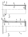
- the apparent from Figure 1 cylindrical, multi-stage filter system 10 comprises a equipped with spacers 12 and an external filter 10B bearing internal filter 10A and a multi-part filter adapter 20.
- the internal filter 10A is preferably a safety filter in the form of a rigid support basket, for example high quality non-woven polyester or needle felt, possibly with applied filter membrane (Teflon-coated) or with GORE-TEX coating.
- the External filter 10B preferably a conventional and inexpensive working filter, for example, paper or paper-like materials, slipped, stretched or striped.
- the spacers 12 cause internal 10A and external filters 10B do not lie directly on top of each other, so that consequently a cavity 14 between them remains.
- the support basket is opposite to the suction flow A, so that he is streamed on his outside.
- Figure 1 also shows a filter mounting plate 20c of a vacuum conveyor 100 (Fig. 3) with associated Verschraubhülse 30 with the Multi-stage filter system 10 attached to the aid of the filter adapter 20 and at the same time be held together.
- Arrow A shows the air intake direction the vacuum pump device 40.
- the running around the external filter 10B Dashed line 10B ' indicates the course that the surface of the external filter 10B in the reversibly inflated state by, in particular, a counter-blow pulse possibly take.
- FIG 2 is a section of an alternative multi-part filter adapter 20 with a connecting channel 24 can be seen.
- the filter adapter consists of three parts, 20A, 20B and 20C together, wherein 20C simultaneously as a filter mounting plate can serve. Between the filter adapter parts 20A and 20B may be in their telescoped Condition of the external filter 10B are used, which at his upper mouth edge advantageously has a sealing ring 22A, which an air- and / or fluid-tight connection between the external filter 10B and the two filter adapter parts 20A and 20B is enabled.
- the internal filter 10A can with Attachment means, such as bonding, to the filter adapter part 20B be attached air-tight and / or fluid-tight. This is a simple installation for the External filters provided for the internal safety filter due to the rarer Replacement, however, is not necessary.
- connection channel 14 passes through all three filter adapter parts 20A, 20B and 20C, thus connecting the inner and outer filters Cavity 14 with the environment.
- a connection channel 14 passes through all three filter adapter parts 20A, 20B and 20C, thus connecting the inner and outer filters Cavity 14 with the environment.
- Sealing of the filter adapter parts 20A and 20C becomes further sealing rings 22B and 22C.
- the support basket can also be in the direction of the flow A oriented, so flowed on its inside and the external filter on its inside, i. also carry upstream.
- a vacuum conveyor 100 can be seen.
- the vacuum pump device 40 an intake manifold 50, the filter adapter part 20C serving as the filter fixing plate 20C ' and an emptying device 60 to be seen in or on the separator housing 102 of the vacuum conveyor 100 are provided.
- FIGS. 4A and 4B differ itself from the embodiments of Figures 1 and 2 u. a. in that the internal filter 10A is permanently connected to a filter plate 20C '.
- a filter plate 20C ' For this purpose is in the embodiment of Fig. 4A, an annular filter adapter part 20B at one end with the filter plate 20C 'and at the other end with the inner filter 10A Welding connected.
- Another filter adapter part 20A is on the filter adapter part 20B can be connected and clamped by means of an inner / outer threaded connection, such as in the embodiments according to Figures 1 and 2, the outer filter 10 B circumferentially sealingly.
- spacers 12 are separate from the internal filter components that are interchangeable or with the internal filter, z. B. connectable by gluing or welding.
- the filter adapter 20 consists of a trumpet-shaped component of a filter plate 10C '.
- the internal filter 10A is with the peripheral edge of the trumpet-like deformation by welding connected, wherein this internal filter is in two parts and of a tubular Wall part and a plate-like bottom part, which together by welding are connected, as known per se for sintered metals or plastics is. Alternatively, a bond is possible, such as at sintered plastic filters.
Landscapes
- Chemical & Material Sciences (AREA)
- Chemical Kinetics & Catalysis (AREA)
- Filtering Of Dispersed Particles In Gases (AREA)
Applications Claiming Priority (2)
| Application Number | Priority Date | Filing Date | Title |
|---|---|---|---|
| DE20312074U | 2003-08-05 | ||
| DE20312074U DE20312074U1 (de) | 2003-08-05 | 2003-08-05 | Vakuumfördereinrichtung mit einem mehrstufigen Filtersystem |
Publications (2)
| Publication Number | Publication Date |
|---|---|
| EP1504802A1 true EP1504802A1 (fr) | 2005-02-09 |
| EP1504802B1 EP1504802B1 (fr) | 2006-11-29 |
Family
ID=33547258
Family Applications (1)
| Application Number | Title | Priority Date | Filing Date |
|---|---|---|---|
| EP04017271A Expired - Lifetime EP1504802B1 (fr) | 2003-08-05 | 2004-07-22 | Dispositif de transport sous vide avec un système de filtre à plusieurs étages |
Country Status (3)
| Country | Link |
|---|---|
| US (1) | US7354469B2 (fr) |
| EP (1) | EP1504802B1 (fr) |
| DE (2) | DE20312074U1 (fr) |
Families Citing this family (10)
| Publication number | Priority date | Publication date | Assignee | Title |
|---|---|---|---|---|
| DE202007004475U1 (de) | 2007-03-23 | 2008-08-14 | Volkmann Gmbh | Filteranordnung |
| US8114201B2 (en) * | 2008-10-22 | 2012-02-14 | Gore Enterprise Holdings, Inc. | Air pollution control filter elements for filtration systems |
| US8888880B2 (en) * | 2010-10-14 | 2014-11-18 | Air Dynamics Industrial Systems Corporation | Vacuum loader |
| US9555357B2 (en) | 2010-10-14 | 2017-01-31 | Air Dynamics Industrial Systems Corporation | Filter chambers and self-cleaning apparatus for vacuum systems |
| DE102013112132B4 (de) * | 2013-11-05 | 2017-12-14 | Keller Lufttechnik Gmbh & Co. Kg | Verfahren zur Abscheidung von Verunreinigungen aus einem Gasstrom mittels einer Filteranordnung |
| US9200568B1 (en) * | 2014-09-24 | 2015-12-01 | General Electric Company | Inlet air filtration system with self-cleaning filter bag |
| US10159924B2 (en) * | 2014-09-24 | 2018-12-25 | General Electric Company | Inlet air filtration system with self-cleaning hydrophobic filter bag |
| US10252205B2 (en) | 2014-09-26 | 2019-04-09 | Ford Global Technologies, Llc | Air filter element assembly for a motor vehicle |
| US10087898B2 (en) * | 2014-09-26 | 2018-10-02 | Ford Global Technologies Llc | Air filter element assembly for a motor vehicle |
| EP3423166B1 (fr) * | 2016-03-02 | 2020-01-01 | Donaldson Company, Inc. | Element filtrant avec support interieur et methode de filtration |
Citations (3)
| Publication number | Priority date | Publication date | Assignee | Title |
|---|---|---|---|---|
| US3092479A (en) * | 1960-06-01 | 1963-06-04 | Carl W Hedberg | Double bag filter |
| DE2306002A1 (de) * | 1972-06-14 | 1974-01-03 | Aerodyne Dev Corp | Verfahren und vorrichtung zur beseitigung von angesammeltem staub und anderen teilchen |
| JPH04363116A (ja) * | 1991-06-06 | 1992-12-16 | Takuma Co Ltd | 排ガス処理装置 |
Family Cites Families (14)
| Publication number | Priority date | Publication date | Assignee | Title |
|---|---|---|---|---|
| US3885932A (en) * | 1974-01-10 | 1975-05-27 | Super Products Corp | Dust filtration system |
| DE4427753C2 (de) * | 1994-08-05 | 2001-05-17 | Mann & Hummel Filter | Ölabscheider |
| DE19508815A1 (de) * | 1995-03-11 | 1996-09-12 | Mann & Hummel Filter | Luftentölelement |
| US5830250A (en) * | 1996-03-06 | 1998-11-03 | Minnesota Mining And Manufacturing Company | Stepped hot gas filter cartridge |
| DE19645666A1 (de) * | 1996-11-06 | 1998-05-07 | Mann & Hummel Filter | Filtereinsatz |
| CN1297368A (zh) * | 1998-02-28 | 2001-05-30 | 艾美兹公司 | 圆锥状油气分离器 |
| US6099606A (en) * | 1998-03-19 | 2000-08-08 | Donaldson Company, Inc. | Air filtration arrangements having spacer constructions |
| DE29820837U1 (de) * | 1998-11-21 | 1999-01-14 | Glatt Ingenieurtechnik GmbH, 99427 Weimar | Adapter für Abluftfiltersysteme |
| DE19930614A1 (de) * | 1999-07-02 | 2001-01-04 | Mann & Hummel Filter | Filtereinsatz |
| US20030041729A1 (en) * | 1999-12-29 | 2003-03-06 | Finigan Justin J. | Method and apparatus for cleaning filter bags of bag houses |
| US6936085B2 (en) * | 2000-05-10 | 2005-08-30 | Demarco Maxvac Corporation | Vacuum loader |
| US6383244B1 (en) * | 2000-10-20 | 2002-05-07 | Nelson Industries, Inc. | Filter with retained safety element |
| US6416561B1 (en) * | 2000-10-20 | 2002-07-09 | Nelson Industries, Inc. | Open flow filter with safety element |
| DE20104481U1 (de) * | 2001-03-15 | 2001-06-13 | ultrafilter international AG, 42781 Haan | Druckluftfilter |
-
2003
- 2003-08-05 DE DE20312074U patent/DE20312074U1/de not_active Expired - Lifetime
-
2004
- 2004-07-22 DE DE502004002149T patent/DE502004002149D1/de not_active Expired - Lifetime
- 2004-07-22 EP EP04017271A patent/EP1504802B1/fr not_active Expired - Lifetime
- 2004-08-05 US US10/912,650 patent/US7354469B2/en not_active Expired - Lifetime
Patent Citations (3)
| Publication number | Priority date | Publication date | Assignee | Title |
|---|---|---|---|---|
| US3092479A (en) * | 1960-06-01 | 1963-06-04 | Carl W Hedberg | Double bag filter |
| DE2306002A1 (de) * | 1972-06-14 | 1974-01-03 | Aerodyne Dev Corp | Verfahren und vorrichtung zur beseitigung von angesammeltem staub und anderen teilchen |
| JPH04363116A (ja) * | 1991-06-06 | 1992-12-16 | Takuma Co Ltd | 排ガス処理装置 |
Non-Patent Citations (1)
| Title |
|---|
| PATENT ABSTRACTS OF JAPAN * |
Also Published As
| Publication number | Publication date |
|---|---|
| DE20312074U1 (de) | 2004-12-23 |
| US7354469B2 (en) | 2008-04-08 |
| DE502004002149D1 (de) | 2007-01-11 |
| US20050060969A1 (en) | 2005-03-24 |
| EP1504802B1 (fr) | 2006-11-29 |
Similar Documents
| Publication | Publication Date | Title |
|---|---|---|
| EP0695572B1 (fr) | Séparateur d'huile | |
| EP2703059B1 (fr) | Agencement de filtration et procédé de fabrication d'un logement de filtre | |
| EP2249943A1 (fr) | Filtre à soufflets multiples, à rendement accru | |
| EP2049222B1 (fr) | Dispositif de filtration | |
| EP2881156B1 (fr) | Élément de filtre ayant un canal de dérivation ainsi qu'agencement de filtre doté d'un élément de filtre | |
| EP2862614B2 (fr) | Système de filtre équipé d'un élément de filtre | |
| WO2011124675A1 (fr) | Séparateur à cyclone | |
| EP2851110A1 (fr) | Élément de filtre et système de filtre équipé d'un élément de filtre | |
| EP1504802B1 (fr) | Dispositif de transport sous vide avec un système de filtre à plusieurs étages | |
| EP2136899A1 (fr) | Filtre à carburant | |
| EP2865433A2 (fr) | Élément de filtre et système de filtre pour un milieu fluidique, notamment du carburant diesel | |
| DE102014002631B4 (de) | Filterelement und Fluidfilter mit radialer Entlüftungsbohrung | |
| DE102009005158A1 (de) | Kombinationsfilter | |
| EP4426467B1 (fr) | Élément filtrant rond et dispositif filtrant | |
| DE102013014489A1 (de) | Filterelement und Filtersystem mit einem Filterelement | |
| EP1124056B1 (fr) | Filtre à carburant | |
| WO2015018779A1 (fr) | Crible séparateur d'eau pour un élément filtrant dans un filtre de liquide | |
| EP2702261B1 (fr) | Élément de filtration d'air et boîtier pour élément de filtration d'air | |
| DE202009013103U1 (de) | Zylindrische Filterpatrone für eine Filtervorrichtung zum Entfernen von Feinstäuben aus einem staubbeladenen Gasstrom sowie Filtervorrichtung und Filteranlage mit selbiger | |
| EP1911503A2 (fr) | Dispositif de filtrage, en particulier destiné à la filtration d'air de combustion dans des moteurs à combustion interne | |
| DE10240666B4 (de) | Flüssigkeitsfilter, insbesondere für Getriebeöl in Kraftfahrzeugen | |
| WO1998028058A1 (fr) | Procede et dispositif de filtration en continu de liquides | |
| DE102014119441A1 (de) | Vorrichtung zur Entnahme einer Probe aus kommunalen und/oder industriellen Abwässern | |
| DE102014012944A1 (de) | Filtersystem mit Filterelement | |
| DE102015000942A1 (de) | Filterelement, Filtervorrichtung und Filtergehäuse einer Filtervorrichtung |
Legal Events
| Date | Code | Title | Description |
|---|---|---|---|
| PUAI | Public reference made under article 153(3) epc to a published international application that has entered the european phase |
Free format text: ORIGINAL CODE: 0009012 |
|
| AK | Designated contracting states |
Kind code of ref document: A1 Designated state(s): AT BE BG CH CY CZ DE DK EE ES FI FR GB GR HU IE IT LI LU MC NL PL PT RO SE SI SK TR |
|
| AX | Request for extension of the european patent |
Extension state: AL HR LT LV MK |
|
| 17P | Request for examination filed |
Effective date: 20050808 |
|
| AKX | Designation fees paid |
Designated state(s): DE FR GB IT |
|
| GRAP | Despatch of communication of intention to grant a patent |
Free format text: ORIGINAL CODE: EPIDOSNIGR1 |
|
| GRAJ | Information related to disapproval of communication of intention to grant by the applicant or resumption of examination proceedings by the epo deleted |
Free format text: ORIGINAL CODE: EPIDOSDIGR1 |
|
| GRAP | Despatch of communication of intention to grant a patent |
Free format text: ORIGINAL CODE: EPIDOSNIGR1 |
|
| GRAS | Grant fee paid |
Free format text: ORIGINAL CODE: EPIDOSNIGR3 |
|
| GRAA | (expected) grant |
Free format text: ORIGINAL CODE: 0009210 |
|
| AK | Designated contracting states |
Kind code of ref document: B1 Designated state(s): DE FR GB IT |
|
| REG | Reference to a national code |
Ref country code: GB Ref legal event code: FG4D Free format text: NOT ENGLISH |
|
| REF | Corresponds to: |
Ref document number: 502004002149 Country of ref document: DE Date of ref document: 20070111 Kind code of ref document: P |
|
| GBT | Gb: translation of ep patent filed (gb section 77(6)(a)/1977) |
Effective date: 20070131 |
|
| ET | Fr: translation filed | ||
| PLBE | No opposition filed within time limit |
Free format text: ORIGINAL CODE: 0009261 |
|
| STAA | Information on the status of an ep patent application or granted ep patent |
Free format text: STATUS: NO OPPOSITION FILED WITHIN TIME LIMIT |
|
| 26N | No opposition filed |
Effective date: 20070830 |
|
| REG | Reference to a national code |
Ref country code: FR Ref legal event code: PLFP Year of fee payment: 13 |
|
| REG | Reference to a national code |
Ref country code: FR Ref legal event code: PLFP Year of fee payment: 14 |
|
| REG | Reference to a national code |
Ref country code: FR Ref legal event code: PLFP Year of fee payment: 15 |
|
| PGFP | Annual fee paid to national office [announced via postgrant information from national office to epo] |
Ref country code: IT Payment date: 20230731 Year of fee payment: 20 Ref country code: GB Payment date: 20230724 Year of fee payment: 20 |
|
| PGFP | Annual fee paid to national office [announced via postgrant information from national office to epo] |
Ref country code: FR Payment date: 20230720 Year of fee payment: 20 Ref country code: DE Payment date: 20230926 Year of fee payment: 20 |
|
| REG | Reference to a national code |
Ref country code: DE Ref legal event code: R071 Ref document number: 502004002149 Country of ref document: DE |
|
| REG | Reference to a national code |
Ref country code: GB Ref legal event code: PE20 Expiry date: 20240721 |
|
| PG25 | Lapsed in a contracting state [announced via postgrant information from national office to epo] |
Ref country code: GB Free format text: LAPSE BECAUSE OF EXPIRATION OF PROTECTION Effective date: 20240721 |
|
| PG25 | Lapsed in a contracting state [announced via postgrant information from national office to epo] |
Ref country code: GB Free format text: LAPSE BECAUSE OF EXPIRATION OF PROTECTION Effective date: 20240721 |