EP1504840A1 - Assemblage brasé par recouvrement comprenant une pluralité de tôles - Google Patents
Assemblage brasé par recouvrement comprenant une pluralité de tôles Download PDFInfo
- Publication number
- EP1504840A1 EP1504840A1 EP03102358A EP03102358A EP1504840A1 EP 1504840 A1 EP1504840 A1 EP 1504840A1 EP 03102358 A EP03102358 A EP 03102358A EP 03102358 A EP03102358 A EP 03102358A EP 1504840 A1 EP1504840 A1 EP 1504840A1
- Authority
- EP
- European Patent Office
- Prior art keywords
- edge
- cover plate
- solder joint
- gap
- joint according
- Prior art date
- Legal status (The legal status is an assumption and is not a legal conclusion. Google has not performed a legal analysis and makes no representation as to the accuracy of the status listed.)
- Withdrawn
Links
- 238000005476 soldering Methods 0.000 title claims description 87
- 239000002184 metal Substances 0.000 title description 3
- 229910000679 solder Inorganic materials 0.000 claims abstract description 87
- 125000006850 spacer group Chemical group 0.000 claims abstract description 10
- 239000011324 bead Substances 0.000 claims description 13
- 238000007373 indentation Methods 0.000 claims description 12
- 239000000463 material Substances 0.000 claims description 8
- 238000000034 method Methods 0.000 claims 1
- 230000005540 biological transmission Effects 0.000 description 2
- 238000010276 construction Methods 0.000 description 2
- 238000009423 ventilation Methods 0.000 description 2
- 230000007423 decrease Effects 0.000 description 1
- 238000010438 heat treatment Methods 0.000 description 1
- 239000012535 impurity Substances 0.000 description 1
- 230000002787 reinforcement Effects 0.000 description 1
- 239000000725 suspension Substances 0.000 description 1
- 239000005028 tinplate Substances 0.000 description 1
- 238000003466 welding Methods 0.000 description 1
Images

Classifications
-
- B—PERFORMING OPERATIONS; TRANSPORTING
- B23—MACHINE TOOLS; METAL-WORKING NOT OTHERWISE PROVIDED FOR
- B23K—SOLDERING OR UNSOLDERING; WELDING; CLADDING OR PLATING BY SOLDERING OR WELDING; CUTTING BY APPLYING HEAT LOCALLY, e.g. FLAME CUTTING; WORKING BY LASER BEAM
- B23K1/00—Soldering, e.g. brazing, or unsoldering
- B23K1/0008—Soldering, e.g. brazing, or unsoldering specially adapted for particular articles or work
-
- B—PERFORMING OPERATIONS; TRANSPORTING
- B23—MACHINE TOOLS; METAL-WORKING NOT OTHERWISE PROVIDED FOR
- B23K—SOLDERING OR UNSOLDERING; WELDING; CLADDING OR PLATING BY SOLDERING OR WELDING; CUTTING BY APPLYING HEAT LOCALLY, e.g. FLAME CUTTING; WORKING BY LASER BEAM
- B23K1/00—Soldering, e.g. brazing, or unsoldering
- B23K1/005—Soldering by means of radiant energy
-
- B—PERFORMING OPERATIONS; TRANSPORTING
- B23—MACHINE TOOLS; METAL-WORKING NOT OTHERWISE PROVIDED FOR
- B23K—SOLDERING OR UNSOLDERING; WELDING; CLADDING OR PLATING BY SOLDERING OR WELDING; CUTTING BY APPLYING HEAT LOCALLY, e.g. FLAME CUTTING; WORKING BY LASER BEAM
- B23K1/00—Soldering, e.g. brazing, or unsoldering
- B23K1/14—Soldering, e.g. brazing, or unsoldering specially adapted for soldering seams
-
- B—PERFORMING OPERATIONS; TRANSPORTING
- B23—MACHINE TOOLS; METAL-WORKING NOT OTHERWISE PROVIDED FOR
- B23K—SOLDERING OR UNSOLDERING; WELDING; CLADDING OR PLATING BY SOLDERING OR WELDING; CUTTING BY APPLYING HEAT LOCALLY, e.g. FLAME CUTTING; WORKING BY LASER BEAM
- B23K1/00—Soldering, e.g. brazing, or unsoldering
- B23K1/20—Preliminary treatment of work or areas to be soldered, e.g. in respect of a galvanic coating
-
- B—PERFORMING OPERATIONS; TRANSPORTING
- B23—MACHINE TOOLS; METAL-WORKING NOT OTHERWISE PROVIDED FOR
- B23K—SOLDERING OR UNSOLDERING; WELDING; CLADDING OR PLATING BY SOLDERING OR WELDING; CUTTING BY APPLYING HEAT LOCALLY, e.g. FLAME CUTTING; WORKING BY LASER BEAM
- B23K26/00—Working by laser beam, e.g. welding, cutting or boring
- B23K26/20—Bonding
- B23K26/21—Bonding by welding
- B23K26/24—Seam welding
- B23K26/244—Overlap seam welding
-
- B—PERFORMING OPERATIONS; TRANSPORTING
- B23—MACHINE TOOLS; METAL-WORKING NOT OTHERWISE PROVIDED FOR
- B23K—SOLDERING OR UNSOLDERING; WELDING; CLADDING OR PLATING BY SOLDERING OR WELDING; CUTTING BY APPLYING HEAT LOCALLY, e.g. FLAME CUTTING; WORKING BY LASER BEAM
- B23K33/00—Specially-profiled edge portions of workpieces for making soldering or welding connections; Filling the seams formed thereby
- B23K33/004—Filling of continuous seams
- B23K33/008—Filling of continuous seams for automotive applications
-
- B—PERFORMING OPERATIONS; TRANSPORTING
- B62—LAND VEHICLES FOR TRAVELLING OTHERWISE THAN ON RAILS
- B62D—MOTOR VEHICLES; TRAILERS
- B62D25/00—Superstructure or monocoque structure sub-units; Parts or details thereof not otherwise provided for
- B62D25/20—Floors or bottom sub-units
-
- B—PERFORMING OPERATIONS; TRANSPORTING
- B62—LAND VEHICLES FOR TRAVELLING OTHERWISE THAN ON RAILS
- B62D—MOTOR VEHICLES; TRAILERS
- B62D27/00—Connections between superstructure or understructure sub-units
- B62D27/02—Connections between superstructure or understructure sub-units rigid
- B62D27/023—Assembly of structural joints
-
- B—PERFORMING OPERATIONS; TRANSPORTING
- B62—LAND VEHICLES FOR TRAVELLING OTHERWISE THAN ON RAILS
- B62D—MOTOR VEHICLES; TRAILERS
- B62D33/00—Superstructures for load-carrying vehicles
- B62D33/02—Platforms; Open load compartments
-
- F—MECHANICAL ENGINEERING; LIGHTING; HEATING; WEAPONS; BLASTING
- F16—ENGINEERING ELEMENTS AND UNITS; GENERAL MEASURES FOR PRODUCING AND MAINTAINING EFFECTIVE FUNCTIONING OF MACHINES OR INSTALLATIONS; THERMAL INSULATION IN GENERAL
- F16B—DEVICES FOR FASTENING OR SECURING CONSTRUCTIONAL ELEMENTS OR MACHINE PARTS TOGETHER, e.g. NAILS, BOLTS, CIRCLIPS, CLAMPS, CLIPS OR WEDGES; JOINTS OR JOINTING
- F16B5/00—Joining sheets or plates, e.g. panels, to one another or to strips or bars parallel to them
- F16B5/08—Joining sheets or plates, e.g. panels, to one another or to strips or bars parallel to them by means of welds or the like
-
- B—PERFORMING OPERATIONS; TRANSPORTING
- B23—MACHINE TOOLS; METAL-WORKING NOT OTHERWISE PROVIDED FOR
- B23K—SOLDERING OR UNSOLDERING; WELDING; CLADDING OR PLATING BY SOLDERING OR WELDING; CUTTING BY APPLYING HEAT LOCALLY, e.g. FLAME CUTTING; WORKING BY LASER BEAM
- B23K2101/00—Articles made by soldering, welding or cutting
- B23K2101/006—Vehicles
-
- B—PERFORMING OPERATIONS; TRANSPORTING
- B23—MACHINE TOOLS; METAL-WORKING NOT OTHERWISE PROVIDED FOR
- B23K—SOLDERING OR UNSOLDERING; WELDING; CLADDING OR PLATING BY SOLDERING OR WELDING; CUTTING BY APPLYING HEAT LOCALLY, e.g. FLAME CUTTING; WORKING BY LASER BEAM
- B23K2101/00—Articles made by soldering, welding or cutting
- B23K2101/18—Sheet panels
Definitions
- the invention relates to a solder joint of a plurality of sheets according to the Preamble of claim 1.
- the object of the invention is to make a solder joint so that these Reliably has a high strength.
- soldering gap in the region of the edge between the cover plate and floor panel is arranged, which is at least partially filled with solder material, creates a well-defined solder joint with better reproducible and higher Strength values as known from the prior art.
- Soldering flows into the soldering material in the soldering gap and fills the soldering gap in essential completely, resulting in a of the areal extent her seen exactly defined solder joint between deck and floor panel in entire area of the soldering gap arises.
- the soldering gap is defined by a gap width and a gap width.
- the gap width results from the distance between the opposite surfaces of the cover plate and Floor panel.
- the gap width is determined by the distance in which one between Cover plate and bottom plate arranged boundary edge away from the edge is arranged.
- the boundary edge can be created in different ways Preferred embodiments will be in the following embodiments of the Invention described.
- the soldering gap at the edge has a gap width which is greater than the thinner sheet and the smaller one is too thicker than the thicker sheet of the two connecting sheets cover plate and bottom plate. If you put the thicknesses more usual Based on sheets for which this type of solder joint is suitable, the Gap width of the soldering gap at the edge of a gap width between 0.2 mm and 5 mm be, with a preferred gap width between 0.5 mm to 2 mm is to be considered. If the gap width of the soldering gap is too small, the result is known prior art disadvantages of uncontrolled solder flow. If the gap width is too large, on the one hand, the solder consumption is too large, and the Soldering gap may u.U.
- the gap width of the soldering gap can also deviate therefrom, in particular to larger gap widths than 5 mm.
- the soldering gap has a gap width, measured from the edge of the Cover plates, between 0.5 mm and 5 mm.
- the gap width results in essentially by the application of the measures described below and is characterized in that the gap width of the soldering slit decreases a gap thickness, which is due to the direct contact of the sheets or more Elements results. Due to the predetermined gap width arises at the edge of Cover plates a direct solder joint of the gap width of the soldering gap between cover plate and floor panel. Unless of course, a bigger one Solder order, so that additionally forms a fillet weld of the known type, which leads to a further increase in strength.
- the soldering gap is formed by at least one center plate between Cover plate and bottom plate is arranged, wherein the edge of the center panel is set back from the edge of the cover plate. If three or more Be soldered plates, the middle plate or the middle plates is something cut back relative to the edge of the cover plate. This creates the Soldering gap without additional design measures.
- the gap width of the soldering gap corresponds approximately to the thickness of the middle plate or the sum of the thicknesses of medium sheets.
- the soldering gap formed by a spacer between the cover plate and floor panel arranged is, wherein the edge of the spacer relative to the edge of the cover plate is reset.
- the solder gap is generated here by e.g. a tin plate between the cover plate and bottom plate is clamped.
- the edge of the Sheet metal disc is offset from the edge of the cover plate, the arises Soldering gap as described above without further action.
- the gap width the soldering gap then corresponds to the thickness of the spacer.
- the spacer consists of a wire along the edge is arranged.
- This wire is bent so that it is to be soldered along the Edge runs with a certain distance.
- the gap width of the soldering gap through the Wire diameter determined.
- the soldering gap is formed by cover plate and / or Floor panel have at least one indentation in the region of the edge. These Indentation can be pressed as an expression in one of the sheets or as Paragraph executed in one of the sheets. This creates the soldering gap already due to the arrangement of the two sheets on each other, since the indentation of the edge the cover plate keeps to a defined distance, which is determined by the depth of the Indentation is determined.
- the indentation in the form of a bead is in one imprinted the sheets, with a depth as described above for Adjusting the gap width of the soldering gap and with a distance from the edge, whereby the gap width of the soldering gap is predetermined.
- the beads are therefore parallel to the edge arranged.
- the beads can have any shape, In particular, a plurality of beads can also be arranged along the edge. It is important that at least sections of the defined soldering gap Gap width and gap width arises.
- beads in cover plate and bottom plate are such arranged that they serve both the postioning of the sheets themselves as well create the soldering gap.
- the beads are to match each other in both sheets imprinted, wherein a bead has a smaller depth than the other.
- the indentation is executed as a paragraph. That is, the two plates are just on top of each other, only at the edge of the cover plate is the Soldering gap formed by the paragraph. This can be z. B along a longitudinal edge in Form of a fold or a contour edge in one of the sheets folded or be pressed. For thick sheets, the paragraph by mechanical Processing be created by material in the form of the soldering gap along the Edge is removed.
- a depression causes a constant gap width of the soldering gap between cover plate and floor plate, d. H. the one in the soldering gap Solder material has a constant thickness over the gap width of the soldering gap. This is a continuous over the entire gap width of the soldering gap Power transmission guaranteed.
- a depression causes a Edge of the cover plate increasing gap width of the soldering gap, d. H. the im Soldering solder located at the edge of the cover plate has a larger Thickness than at the opposite end of the soldering gap.
- Such Arrangement may be useful if the solder material very evenly in the Soldering must flow.
- the edge of the cover sheet is the edge of a cutout in the Be cover plate, the cut is mainly introduced into the cover plate, to perform the soldering with the floor panel.
- the section as a hole in the cover plate or as a recess at the edge of the cover plate be executed.
- the solder joint By restricting the solder joint to the area of the Section is the dimension, d. H. the extension of the solder joint exactly established. If the cutout is a hole in the cover plate, soldering will occur just fill the hole with solder. Through the soldering gap that covers the hole, then the exact extent of the solder joint between cover plate and Floor panel set.
- the inventive idea is also valid if the edge of the cover sheet is the outer one Boundary of the cover plate is. This is the case when the two sheets are on the edge the cover sheet is to be soldered. Then by one of the above Measures the soldering gap to be generated so that at the edge of the cover plate of the said soldering gap is formed. This also allows the edge soldering strength be carried out advantageously.
- the bottom plate in the Region of the edge of the cover plate also has an edge. This is e.g. the case when both sheets lie flat on each other and predominantly the have the same edge as z. B. is known in welding flanges. Then it will be this solder joint by means of the inventive soldering gap a higher strength exhibit.
- solder joint according to one of the previous Claims especially in the connection of body parts with each other and / or fitting parts in the automotive industry.
- soldering in this way manufacturable, in which thin sheets, preferably between 0.3 mm and 5 mm are connected by soldering.
- Applications in vehicle construction "such as soldering of suspension parts may be Appliances for household appliances, heating and ventilation equipment or in the Plant construction.
- the inventive solder joint can also find use in the connection of tubular components, wherein a tube with a smaller circumference in a Pipe with a larger circumference is inserted and the soldering gap on the edge of the pipe with larger scale arises.
- the cross section of the tube is arbitrary, ie not only round, but also z. B. rectangular as in ventilation ducts.
- the soldering gap arises then in sections or completely circulating, depending on the requirements of the Solder joint.
- this solder joint in particular in the automated Laser soldering can be used.
- the laser beam in the Soldering can radiate and thus the sheets to be joined faster and more reliable by the laser beam to the temperature required for the soldering heated as this would be the case without soldering.
- Fig. 1 and Fig. 2 show an inventive solder joint 1, by means of which a Base plate 2, a cover plate 3 and an intermediate plate 4 in a section 5 of the Cover plates 3 are joined.
- the soldering gap 6 runs around the cutout 5 and is completely filled with the solder material of the solder seam 7.
- the soldering gap 6 is formed by the opposite section 5 larger cutout 8 in the intermediate plate 4.
- Seine Gap width t corresponds to the thickness of the intermediate plate 4, its gap width a is determined by the differences in the dimensions of the cutouts.
- the edge of the cover plate 3 is here the edge of the cutout 5, d. H. where the Solder 1 is arranged.
- an inventive solder joint 1 is similar to that already shown in FIG. 1 and 2 described. Only difference is that due to the larger gap width the cutouts 5, 8 in the cover plate 3 and intermediate plate 4 now two solder joints 9 and 10 in the cutouts 5, 8 are introduced.
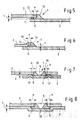
- Fig. 5 shows an inventive solder joint 1, in which between bottom plate. 2 and cover plate 3, a wire 11 is arranged as a spacer.
- the gap width t of Soldering gap 6 is determined by the thickness of the wire 11, the gap width a the arrangement of the wire 11 at a certain distance from the edge 13 of the Cover sheets 3.
- Fig. 6 an inventive solder joint 1 is shown, in which the cover plate. 3 a paragraph 14, wherein the soldering gap 6 is determined here by the height of the paragraph, gives the gap width t, and the gap width of the paragraph 14, results the gap width a.
- the solder seam 15 is again designed so that the soldering gap. 6 is completely filled and formed on the edge 16 of the cover plate 3 a fillet weld becomes.
- the inventive solder joint 1 in Fig. 7 has indentations in the form of two Beading 17 in the floor panel 2. Is the cover plate 3 with the cutout 5 on the Beading 17, the soldering gap 6 forms with the gap width t and the gap width a by the depth of the beads 17 and their distance from the edge of the cutout 5 of the Cover plates 3.
- the double solder seams 18 are introduced in the cutout 5, her Solder also fills the solder gap 6.
- FIG. 8 A further variant of the idea from FIG. 7 is shown in FIG. 8, in which the Solder 1 is produced by a depression 19 in the floor panel 2. there the indentation 19 has a larger dimension than the cutout 5 in FIG Cover plate 3.
- the soldering gap 6 with the gap width t and the gap width a from the difference the dimensions of indentation 19 and section 5.
- Cover plate 3 and bottom plate 2 are substantially directly on top of each other, only in the area of the solder joint 1, said soldering gap 6 is formed.
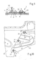
- Fig. 9 shows an embodiment of the inventive solder joint 1 for a metal sheet 20, which is soldered by means of a Lötflansches 21 on a floor panel 2, wherein the Solder flange 21 assumes the function of the cover plate previously described.
- the Solder flange 21 assumes the function of the cover plate previously described.
- two solder gaps 6 between Lötflansch 21 and bottom plate. 3 formed, with the gap width a or b and the gap width t.
- the connection between Lötflansch 21 and bottom plate is made, wherein the solder seams 23 extend on both sides of the soldering flange 21.
- the solder joint 1 is a very high Power transmission perpendicular to the bottom plate 2 allows.
- Fig. 10 is a partial view of a motor vehicle body is represented by means of the inventive solder joint 1 are joined.
- An outer panel 24 of an A-pillar is connected to the outer panel 25 of an upper front side member by means of Solder joints 1 connected.
- the outer panel 25 of the longitudinal member three cutouts 26, in each of which double solder seams 27 are introduced.
- the inventive soldering gaps are impressions in the Outer sheet 24 of the A-pillar generated.
Landscapes
- Engineering & Computer Science (AREA)
- Mechanical Engineering (AREA)
- Chemical & Material Sciences (AREA)
- Combustion & Propulsion (AREA)
- Transportation (AREA)
- Physics & Mathematics (AREA)
- Optics & Photonics (AREA)
- General Engineering & Computer Science (AREA)
- Plasma & Fusion (AREA)
- Connections Effected By Soldering, Adhesion, Or Permanent Deformation (AREA)
- Building Environments (AREA)
- Electric Connection Of Electric Components To Printed Circuits (AREA)
Priority Applications (3)
| Application Number | Priority Date | Filing Date | Title |
|---|---|---|---|
| EP03102358A EP1504840A1 (fr) | 2003-07-30 | 2003-07-30 | Assemblage brasé par recouvrement comprenant une pluralité de tôles |
| EP04103405A EP1502691B1 (fr) | 2003-07-30 | 2004-07-16 | Assemblage brasé par recouvrement comprenant une pluralité de tôles avec un espaceur située entre une tôle supérieure et une tôle inférieure |
| DE502004006885T DE502004006885D1 (de) | 2003-07-30 | 2004-07-16 | Lötverbindung mit mehreren überlappenden Blechen und mit einem zwischen einem oberen Deckblech und einem unteren Bodenblech angeordneten Distanzstück |
Applications Claiming Priority (1)
| Application Number | Priority Date | Filing Date | Title |
|---|---|---|---|
| EP03102358A EP1504840A1 (fr) | 2003-07-30 | 2003-07-30 | Assemblage brasé par recouvrement comprenant une pluralité de tôles |
Publications (1)
| Publication Number | Publication Date |
|---|---|
| EP1504840A1 true EP1504840A1 (fr) | 2005-02-09 |
Family
ID=33547781
Family Applications (2)
| Application Number | Title | Priority Date | Filing Date |
|---|---|---|---|
| EP03102358A Withdrawn EP1504840A1 (fr) | 2003-07-30 | 2003-07-30 | Assemblage brasé par recouvrement comprenant une pluralité de tôles |
| EP04103405A Expired - Lifetime EP1502691B1 (fr) | 2003-07-30 | 2004-07-16 | Assemblage brasé par recouvrement comprenant une pluralité de tôles avec un espaceur située entre une tôle supérieure et une tôle inférieure |
Family Applications After (1)
| Application Number | Title | Priority Date | Filing Date |
|---|---|---|---|
| EP04103405A Expired - Lifetime EP1502691B1 (fr) | 2003-07-30 | 2004-07-16 | Assemblage brasé par recouvrement comprenant une pluralité de tôles avec un espaceur située entre une tôle supérieure et une tôle inférieure |
Country Status (2)
| Country | Link |
|---|---|
| EP (2) | EP1504840A1 (fr) |
| DE (1) | DE502004006885D1 (fr) |
Cited By (5)
| Publication number | Priority date | Publication date | Assignee | Title |
|---|---|---|---|---|
| FR2926782A1 (fr) * | 2008-01-29 | 2009-07-31 | Peugeot Citroen Automobiles Sa | Dispositif et procede de positionnement de deux pieces l'une sur l'autre. |
| WO2012007667A1 (fr) * | 2010-07-15 | 2012-01-19 | Renault S.A.S. | Assemblage par brasage unilateral inductif d'une tole fine et d'un profile creux, et le procede correspondant |
| DE102014000618A1 (de) * | 2014-01-18 | 2015-07-23 | Audi Ag | Verbindungsnaht zwischen zwei dünnwandigen Blechbauteilen |
| US20190017755A1 (en) * | 2015-12-22 | 2019-01-17 | Lg Electronics Inc. | Air conditioner and method of manufacturing the same |
| FR3145696A1 (fr) * | 2023-02-13 | 2024-08-16 | Psa Automobiles Sa | Procédé d’assemblage d’un ensemble d’au moins trois tôles, et assemblage résultant. |
Families Citing this family (6)
| Publication number | Priority date | Publication date | Assignee | Title |
|---|---|---|---|---|
| DE102006011175A1 (de) * | 2006-03-10 | 2007-09-13 | Hella Kgaa Hueck & Co. | Hartlötverfahren mit walzplattiertem Lotdepot |
| DE102006014980A1 (de) * | 2006-03-31 | 2007-10-18 | Dr.Ing.H.C. F. Porsche Ag | Verbindungsanordnung von Trägerelementen einer Fahrzeugkarosserie |
| JP2014019268A (ja) * | 2012-07-17 | 2014-02-03 | Toyota Motor Corp | 異種板材の接合構造及びその接合方法 |
| DE102015204107A1 (de) * | 2015-03-06 | 2016-09-08 | Bayerische Motoren Werke Aktiengesellschaft | Verfahren zum Ausbilden einer Fügeverbindung zwischen zwei Bauteilen |
| JP2024106737A (ja) * | 2023-01-27 | 2024-08-08 | 株式会社神戸製鋼所 | 溶接構造体の製造方法及び溶接構造体 |
| CN119426784A (zh) * | 2024-09-30 | 2025-02-14 | 富联裕展科技(深圳)有限公司 | 复合金属边框的加工方法、复合金属边框及电子设备 |
Citations (9)
| Publication number | Priority date | Publication date | Assignee | Title |
|---|---|---|---|---|
| DE503660C (de) * | 1930-07-24 | Elek Sche Loet Und Schweiss Ge | Loetnaht fuer sich ueberlappende Blechlaengsraender, insbesondere fuer Konservendosenmaentel | |
| JPS54137455A (en) * | 1978-04-18 | 1979-10-25 | Mitsubishi Electric Corp | Brazing |
| JPS6046864A (ja) * | 1983-08-24 | 1985-03-13 | Mitsubishi Electric Corp | ろう付溶接方法 |
| JPS62212056A (ja) * | 1986-03-13 | 1987-09-18 | Nasu Bankin Kogyo:Kk | 金属板の接合方法 |
| DE3820848A1 (de) * | 1987-09-23 | 1989-04-13 | Fraunhofer Ges Forschung | Verfahren und vorrichtung zum fuegen von werkstuecken mittels laserstrahlung |
| EP0552468A1 (fr) * | 1991-12-24 | 1993-07-28 | FIAT AUTO S.p.A. | Réservoir de combustible pour voitures et procédés pour sa fabrication |
| US5645364A (en) * | 1993-06-25 | 1997-07-08 | Fuji Jukogyo Kabushiki Kaisha | Structure for joining plate elements |
| US6109506A (en) * | 1998-12-23 | 2000-08-29 | Ford Global Technologies, Inc. | Method of enhancing a joined metal assembly |
| JP2001087853A (ja) * | 1999-09-21 | 2001-04-03 | Suzuki Motor Corp | 管状部材の接合構造及び管状部材の接合方法 |
Family Cites Families (4)
| Publication number | Priority date | Publication date | Assignee | Title |
|---|---|---|---|---|
| JPS5766204U (fr) * | 1980-10-09 | 1982-04-20 | ||
| EP0787557A3 (fr) * | 1996-01-30 | 1998-07-22 | Suzuki Motor Corporation | Procédé d'assemblage d'éléments en aluminium |
| JP3472694B2 (ja) * | 1998-01-07 | 2003-12-02 | 株式会社オートネットワーク技術研究所 | ロウ付け方法及びロウ付け構造 |
| JP2001030067A (ja) * | 1999-07-21 | 2001-02-06 | Showa Alum Corp | 金属材のろう付方法 |
-
2003
- 2003-07-30 EP EP03102358A patent/EP1504840A1/fr not_active Withdrawn
-
2004
- 2004-07-16 EP EP04103405A patent/EP1502691B1/fr not_active Expired - Lifetime
- 2004-07-16 DE DE502004006885T patent/DE502004006885D1/de not_active Expired - Lifetime
Patent Citations (9)
| Publication number | Priority date | Publication date | Assignee | Title |
|---|---|---|---|---|
| DE503660C (de) * | 1930-07-24 | Elek Sche Loet Und Schweiss Ge | Loetnaht fuer sich ueberlappende Blechlaengsraender, insbesondere fuer Konservendosenmaentel | |
| JPS54137455A (en) * | 1978-04-18 | 1979-10-25 | Mitsubishi Electric Corp | Brazing |
| JPS6046864A (ja) * | 1983-08-24 | 1985-03-13 | Mitsubishi Electric Corp | ろう付溶接方法 |
| JPS62212056A (ja) * | 1986-03-13 | 1987-09-18 | Nasu Bankin Kogyo:Kk | 金属板の接合方法 |
| DE3820848A1 (de) * | 1987-09-23 | 1989-04-13 | Fraunhofer Ges Forschung | Verfahren und vorrichtung zum fuegen von werkstuecken mittels laserstrahlung |
| EP0552468A1 (fr) * | 1991-12-24 | 1993-07-28 | FIAT AUTO S.p.A. | Réservoir de combustible pour voitures et procédés pour sa fabrication |
| US5645364A (en) * | 1993-06-25 | 1997-07-08 | Fuji Jukogyo Kabushiki Kaisha | Structure for joining plate elements |
| US6109506A (en) * | 1998-12-23 | 2000-08-29 | Ford Global Technologies, Inc. | Method of enhancing a joined metal assembly |
| JP2001087853A (ja) * | 1999-09-21 | 2001-04-03 | Suzuki Motor Corp | 管状部材の接合構造及び管状部材の接合方法 |
Non-Patent Citations (4)
| Title |
|---|
| PATENT ABSTRACTS OF JAPAN vol. 004, no. 002 (C - 069) 9 January 1980 (1980-01-09) * |
| PATENT ABSTRACTS OF JAPAN vol. 009, no. 176 (M - 398) 20 July 1985 (1985-07-20) * |
| PATENT ABSTRACTS OF JAPAN vol. 012, no. 067 (M - 673) 2 March 1988 (1988-03-02) * |
| PATENT ABSTRACTS OF JAPAN vol. 2000, no. 21 3 August 2001 (2001-08-03) * |
Cited By (9)
| Publication number | Priority date | Publication date | Assignee | Title |
|---|---|---|---|---|
| FR2926782A1 (fr) * | 2008-01-29 | 2009-07-31 | Peugeot Citroen Automobiles Sa | Dispositif et procede de positionnement de deux pieces l'une sur l'autre. |
| WO2012007667A1 (fr) * | 2010-07-15 | 2012-01-19 | Renault S.A.S. | Assemblage par brasage unilateral inductif d'une tole fine et d'un profile creux, et le procede correspondant |
| FR2962670A1 (fr) * | 2010-07-15 | 2012-01-20 | Renault Sa | Assemblage par brasage unilateral inductif d'une tole fine et d'un profile creux, et le procede correspondant. |
| DE102014000618A1 (de) * | 2014-01-18 | 2015-07-23 | Audi Ag | Verbindungsnaht zwischen zwei dünnwandigen Blechbauteilen |
| DE102014000618B4 (de) * | 2014-01-18 | 2016-09-22 | Audi Ag | Verbindungsnaht zwischen zwei dünnwandigen Blechbauteilen |
| US10357849B2 (en) | 2014-01-18 | 2019-07-23 | Audi Ag | Connecting seam between two thin-walled sheet-metal parts |
| US20190017755A1 (en) * | 2015-12-22 | 2019-01-17 | Lg Electronics Inc. | Air conditioner and method of manufacturing the same |
| US10941989B2 (en) * | 2015-12-22 | 2021-03-09 | Lg Electronics Inc. | Air conditioner and method of manufacturing the same |
| FR3145696A1 (fr) * | 2023-02-13 | 2024-08-16 | Psa Automobiles Sa | Procédé d’assemblage d’un ensemble d’au moins trois tôles, et assemblage résultant. |
Also Published As
| Publication number | Publication date |
|---|---|
| DE502004006885D1 (de) | 2008-06-05 |
| EP1502691B1 (fr) | 2008-04-23 |
| EP1502691A1 (fr) | 2005-02-02 |
Similar Documents
| Publication | Publication Date | Title |
|---|---|---|
| DE60217515T2 (de) | Metallplatte zur herstellung eines flachrohrs, flachrohr und verfahren zur herstellung des flachrohrs | |
| DE3855632T2 (de) | Kompositstrukturen und Verfahren zum Herstellen derselben | |
| DE102009023792B4 (de) | Verfahren zum einseitigen, einstufigen Fügen eines Metallblechstapels | |
| EP0894697B1 (fr) | Profilé pour le châssis d'un véhicule utilitaire et procédé pour sa fabrication | |
| DE102011054540B4 (de) | Laser-überlappschweissverfahren für teile aus verzinktem stahlblech | |
| EP1792786A2 (fr) | Boitier absorbeur d'énergie | |
| DE4421905C2 (de) | Verbindungsanordnung für Plattenelemente und Verfahren, um diese zu verbinden | |
| DE60006917T2 (de) | Geschlossenes Strukturteil | |
| EP1502691B1 (fr) | Assemblage brasé par recouvrement comprenant une pluralité de tôles avec un espaceur située entre une tôle supérieure et une tôle inférieure | |
| EP3106823A1 (fr) | Échangeur de chaleur | |
| WO2019042909A1 (fr) | Procédé pour souder des conducteurs électriques au moyen d'ultrasons, et dispositif de soudage de métaux par ultrasons | |
| DE10215441B4 (de) | Y-Knotenstruktur | |
| EP1588784A1 (fr) | Tôle métallique hybride et sa méthode de fabrication | |
| DE4023393C2 (fr) | ||
| EP1180410B1 (fr) | Assemblage soudé de deux tôles minces et méthode pour sa fabrication | |
| EP1799394B1 (fr) | Procédé pour souder unde structure | |
| EP2047924B1 (fr) | Procédé de fabrication d'une glissière de sécurité | |
| DE69903241T2 (de) | Wärmetauscher, insbesondere verflüssiger für kraftfahrzeug und verfahren zu dessen herstellung | |
| DE102020116508B4 (de) | Verbinden von Blechendabschnitten mittels Umformens | |
| DE602005003520T2 (de) | Verfahren zum Herstellen einer Plattenstapelvorform zum hydrostatischen Formen | |
| DE102017223691A1 (de) | Verfahren und Vorrichtung zum Herstellen eines plattenartigen Fluidbehälters | |
| DE102005057259B4 (de) | Verfahren zum Herstellen eines hybriden Bauteils | |
| DE102006002932A1 (de) | Wärmetauscher und Herstellungsverfahren für Wärmetauscher | |
| DE60011681T2 (de) | Methode zur verbindung von stäben beim montieren einer rahmenstruktur | |
| DE102019105536B4 (de) | Fügeverfahren sowie Halbzeug |
Legal Events
| Date | Code | Title | Description |
|---|---|---|---|
| PUAI | Public reference made under article 153(3) epc to a published international application that has entered the european phase |
Free format text: ORIGINAL CODE: 0009012 |
|
| AK | Designated contracting states |
Kind code of ref document: A1 Designated state(s): AT BE BG CH CY CZ DE DK EE ES FI FR GB GR HU IE IT LI LU MC NL PT RO SE SI SK TR |
|
| AX | Request for extension of the european patent |
Extension state: AL LT LV MK |
|
| STAA | Information on the status of an ep patent application or granted ep patent |
Free format text: STATUS: THE APPLICATION HAS BEEN WITHDRAWN |
|
| 18W | Application withdrawn |
Effective date: 20050404 |