EP1504921B1 - Drucktuch und Verfahren zu seiner Herstellung - Google Patents
Drucktuch und Verfahren zu seiner Herstellung Download PDFInfo
- Publication number
- EP1504921B1 EP1504921B1 EP04102529A EP04102529A EP1504921B1 EP 1504921 B1 EP1504921 B1 EP 1504921B1 EP 04102529 A EP04102529 A EP 04102529A EP 04102529 A EP04102529 A EP 04102529A EP 1504921 B1 EP1504921 B1 EP 1504921B1
- Authority
- EP
- European Patent Office
- Prior art keywords
- printing blanket
- carrier layer
- layer
- printing
- blanket
- Prior art date
- Legal status (The legal status is an assumption and is not a legal conclusion. Google has not performed a legal analysis and makes no representation as to the accuracy of the status listed.)
- Expired - Lifetime
Links
- 238000007639 printing Methods 0.000 title claims abstract description 40
- 238000004519 manufacturing process Methods 0.000 title abstract description 4
- 239000002184 metal Substances 0.000 claims abstract description 15
- 239000004744 fabric Substances 0.000 claims abstract description 5
- 229920001169 thermoplastic Polymers 0.000 claims abstract description 5
- 239000000463 material Substances 0.000 claims abstract description 4
- 239000000806 elastomer Substances 0.000 claims abstract 8
- 229920001971 elastomer Polymers 0.000 claims abstract 8
- 239000004416 thermosoftening plastic Substances 0.000 claims abstract 3
- 239000011248 coating agent Substances 0.000 claims description 12
- 238000000576 coating method Methods 0.000 claims description 12
- 238000000034 method Methods 0.000 claims description 9
- 238000005520 cutting process Methods 0.000 claims description 4
- 239000004952 Polyamide Substances 0.000 claims description 3
- 229920002647 polyamide Polymers 0.000 claims description 3
- 239000002985 plastic film Substances 0.000 claims description 2
- 229920006255 plastic film Polymers 0.000 claims description 2
- 239000002318 adhesion promoter Substances 0.000 claims 1
- 238000007645 offset printing Methods 0.000 abstract description 4
- 238000010276 construction Methods 0.000 description 3
- 239000007767 bonding agent Substances 0.000 description 2
- 230000007797 corrosion Effects 0.000 description 2
- 238000005260 corrosion Methods 0.000 description 2
- 239000013536 elastomeric material Substances 0.000 description 2
- 239000012815 thermoplastic material Substances 0.000 description 2
- 238000004073 vulcanization Methods 0.000 description 2
- 239000004820 Pressure-sensitive adhesive Substances 0.000 description 1
- 238000004026 adhesive bonding Methods 0.000 description 1
- 230000015572 biosynthetic process Effects 0.000 description 1
- 239000003599 detergent Substances 0.000 description 1
- 239000003973 paint Substances 0.000 description 1
- 238000002360 preparation method Methods 0.000 description 1
Images

Classifications
-
- B—PERFORMING OPERATIONS; TRANSPORTING
- B41—PRINTING; LINING MACHINES; TYPEWRITERS; STAMPS
- B41N—PRINTING PLATES OR FOILS; MATERIALS FOR SURFACES USED IN PRINTING MACHINES FOR PRINTING, INKING, DAMPING, OR THE LIKE; PREPARING SUCH SURFACES FOR USE AND CONSERVING THEM
- B41N10/00—Blankets or like coverings; Coverings for wipers for intaglio printing
- B41N10/02—Blanket structure
- B41N10/04—Blanket structure multi-layer
-
- B—PERFORMING OPERATIONS; TRANSPORTING
- B41—PRINTING; LINING MACHINES; TYPEWRITERS; STAMPS
- B41N—PRINTING PLATES OR FOILS; MATERIALS FOR SURFACES USED IN PRINTING MACHINES FOR PRINTING, INKING, DAMPING, OR THE LIKE; PREPARING SUCH SURFACES FOR USE AND CONSERVING THEM
- B41N2210/00—Location or type of the layers in multi-layer blankets or like coverings
- B41N2210/06—Backcoats; Back layers; Bottom layers
-
- B—PERFORMING OPERATIONS; TRANSPORTING
- B41—PRINTING; LINING MACHINES; TYPEWRITERS; STAMPS
- B41N—PRINTING PLATES OR FOILS; MATERIALS FOR SURFACES USED IN PRINTING MACHINES FOR PRINTING, INKING, DAMPING, OR THE LIKE; PREPARING SUCH SURFACES FOR USE AND CONSERVING THEM
- B41N2210/00—Location or type of the layers in multi-layer blankets or like coverings
- B41N2210/10—Location or type of the layers in multi-layer blankets or like coverings characterised by inorganic compounds, e.g. pigments
-
- B—PERFORMING OPERATIONS; TRANSPORTING
- B41—PRINTING; LINING MACHINES; TYPEWRITERS; STAMPS
- B41N—PRINTING PLATES OR FOILS; MATERIALS FOR SURFACES USED IN PRINTING MACHINES FOR PRINTING, INKING, DAMPING, OR THE LIKE; PREPARING SUCH SURFACES FOR USE AND CONSERVING THEM
- B41N2210/00—Location or type of the layers in multi-layer blankets or like coverings
- B41N2210/14—Location or type of the layers in multi-layer blankets or like coverings characterised by macromolecular organic compounds
Definitions
- the invention relates to a blanket for use on printing cylinders for in particular offset printing machines according to the preamble of claim 1.
- the Japanese Patent Application 58084294 with the publication number 59209198 is a multi-layered blanket, the carrier layer, which is placed on the printing cylinder of an offset printing machine and inserted with their ends in the clamping channel, a metallic pad.
- the multilayer printing blanket construction is applied in stretched form to this metal sheet and vulcanized.
- the invention has the object of providing a blanket of the type described in such a way that it does not mechanically damage the printing cylinder and that no corrosion due to the different metal pairings can arise. Next, the firm sitting of the metal blanket is to be improved on the printing cylinder.
- the two-sided coating of the metal sheet with thermoplastic or elastomeric material minimizes the risk of corrosion between the metallic carrier layer and the impression cylinder.
- the coating on the top of the metallic carrier layer facilitates the connection to the compressible elastomeric intermediate layer.
- the coating extends over the entire length of the metal sheet. As a result, the coating can not be infiltrated by paint or detergent. The detachment of the coating is largely prevented. The coating is also on the bent ends of the metal sheet and thus leads into the clamping channel of the printing cylinder.
- An advantageous embodiment of the invention is characterized according to claim 2.
- the material polyamide is suitable for the connection on the one hand to the elastomeric layers of the printing blanket and on the other hand gives good resistance to the metallic surface of the printing cylinder.
- the invention also relates to a method for producing a printing blanket according to the preamble of claim 3.
- the method is disclosed in the characterizing part of claim 3.
- the laminate is made continuously from a sheet metal sheet which is coated with thermoplastic or elastomeric material.
- a multilayer blanket sheet is applied to the laminate layer.
- the blanket structure is then cut transversely to the web longitudinal direction over the entire width perpendicular to the upper coating.
- the resulting sections of the blanket structure are dimensioned so that every other section corresponds to the length of two clamping ends.
- the existing blanket structure and the laminate layer are bonded by vulcanization, wherein the upper coating acts as a bonding agent.
- the printing blanket structure is provided with a cold-adhesive bonding agent on its underside prior to application to the carrier layer.
- the sheet-form blanket construction which has been adhered to the backing layer may be cut at intervals to the topcoat such that every other pitch length is exposed by peeling off the respective blanket blank, the pitch length advantageously corresponding to the length of two blanket ends.
- the method according to claim 6 provides that already isolated length-limited blanket structures are applied at intervals to the carrier layer and vulcanized together with the carrier layer.
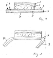
- This in Fig.1 shown blanket has a structure of an elastomeric printing layer 1, an underlying fabric layer 2 and connected to the fabric layer 2, microporous elastomeric intermediate layer 3.
- This blanket structure 1, 2, 3 is firmly applied, for example vulcanized, to a non-stretchable carrier layer 4 consisting of a laminate.
- the laminate layer 4 consists of a stable, but flexible metal sheet 5, which is coated on both sides with each one consisting of polyamide plastic film 6 and 7.
- the laminate layer 4 protrudes in the longitudinal direction over the length of the blanket structure 1, 2, 3 with the formation of ends 8 and 9.
- the printing blanket is shown, wherein the protruding ends 8 and 9 of the carrier layer 4 are angled. The angles are selected according to the position of the clamping channel of the respective printing cylinder.
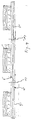
- Fig. 3 is a process step for the preparation of the in Figures 1 and 2 described printing blanket.
- the present as a laminate carrier layer 4 is provided continuously in sheet form.
- a present in sheet form blanket structure 1, 2, 3, which is provided on its underside with a pressure-sensitive adhesive, which has a release force, which allows a mechanical peeling applied.
- the blanket structure is cut at intervals perpendicular to the upper coating 6.
- the resulting portions of the blanket assembly are selected at their intervals such that the gaps created by the cuts 10 alternately have the length of a blanket assembly of a finished blanket and the length of two chucking ends 8 and 9.
- the portions 12 of the blanket assembly which correspond to the length of two clamping ends 8 and 9, are detached from the carrier layer 4 by peeling and removed, so that the in Fig. 4 shown construction arises.
- the configuration according to Fig. 4 in that instead of a web-shaped blanket structure at intervals separate, length-limited blanket structures are applied to the carrier layer 4.
- the distances between the individual blanket structures 1, 2, 3 are determined so that after a later cutting of the respective blanket in the marked by the dotted lines 13 interface blankets are provided, which are cut to length with suitably protruding ends 8 and 9 of the support layer 4, as it is in Fig. 1 represented by a single blanket.
Landscapes
- Printing Plates And Materials Therefor (AREA)
- Glass Compositions (AREA)
- Laminated Bodies (AREA)
- Printing Methods (AREA)
Description
- Die Erfindung betrifft ein Drucktuch zur Verwendung auf Druckzylindern für insbesondere Offset-Druckmaschinen nach dem Oberbegriff des Anspruchs 1.
- Aus dem Patent Abstract of Japan der
japanischen Patentanmeldung 58084294 59209198 - Um die Enden dieses eine metallische Trägerlage aufweisenden Drucktuchs (Metalldrucktuch) in den Einspannkanal einzusetzen, ist es aus der
EP 0 884 176 A1 bekannt, die Enden des Drucktuchs während der Herstellung bereits frei von dem Drucktuchaufbau zu belassen. Die Enden der Trägerlage werden abgeknickt und in den Einspannkanal der Offsetdruckmaschine eingebracht und dort festgespannt. - Der Erfindung liegt die Aufgabe zugrunde, ein Drucktuch der eingangs geschilderten Art derart auszugestalten, dass es den Druckzylinder mechanisch nicht schädigt und dass keinerlei Korrosion aufgrund der unterschiedlichen Metallpaarungen entstehen kann. Weiter soll das feste Sitzen des Metalldrucktuchs auf dem Druckzylinder verbessert werden.
- Der Aufgabe wird erfindungsgemäß durch die im Kennzeichen des Anspruchs 1 genannten Merkmale gelöst.
- Durch die beidseitige Beschichtung des Metallblechs mit thermoplastischem oder elastomerem Werkstoff wird die Korrosionsgefahr zwischen metallischer Trägerlage und Druckzylinder minimiert. Die Beschichtung auf der Oberseite der metallischen Trägerlage erleichtert die Anbindung an die kompressible elastomere Zwischenschicht.
- In dem Drucktuch nach Anspruch 1 erstreckt sich die Beschichtung über die gesamte Länge des Metallblechs. Dadurch kann die Beschichtung nicht durch Farbe oder Waschmittel unterwandert werden. Die Ablösung der Beschichtung ist weitgehend verhindert. Die Beschichtung ist auch auf den abgeknickten Enden des Metallblechs und führt somit bis in den Einspannkanal des Druckzylinders.
- Eine vorteilhafte Ausgestaltung der Erfindung wird gemäß Anspruch 2 gekennzeichnet. Der Werkstoff Polyamid eignet sich zur Anbindung einerseits an die elastomeren Schichten des Drucktuchs und ergibt andererseits eine gute Beständigkeit hinsichtlich der metallischen Oberfläche des Druckzylinders.
- Die Erfindung betrifft auch ein Verfahren zur Herstellung eines Drucktuches nach dem Oberbegriff des Anspruchs 3. Das Verfahren wird im Kennzeichens des Anspruchs 3 offenbart. Das Laminat wird aus einer Metallblechbahn, die mit thermoplastischem oder elastomerem Werkstoff beschichtet wird, kontinuierlich hergestellt. Dann wird eine mehrschichtige Drucktuchaufbaubahn auf die Laminatschicht aufgebracht. In bestimmten Abständen wird dann der Drucktuchaufbau quer zur Bahnlängsrichtung über die gesamte Breite senkrecht bis zur oberen Beschichtung eingeschnitten. Die dabei entstehenden Abschnitte des Drucktuchaufbaus sind so bemessen, dass jeder zweite Abschnitt der Länge zweier Einspannenden entspricht. Anschließend werden der bestehende Drucktuchaufbau und die Laminatschicht durch Vulkanisation verbunden, wobei die obere Beschichtung als Haftvermittler wirkt.
- Anschließend werden durch Abschneiden einzelne Drucktücher erzeugt.
- In vorteilhafter Ausgestaltung des erfindungsgemäßen Verfahrens ist der Drucktuchaufbau vor dem Aufbringen auf die Trägerschicht mit einem kaltklebenden Haftvermittler auf seiner Unterseite versehen.
- Eine weitere vorteilhafte Ausgestaltung des erfindungsgemäßen Verfahrens wird im Anspruch 5 offenbart. Der in Bahnform vorliegende Drucktuchaufbau, der auf der Trägerschicht aufgeklebt worden ist, kann in Abständen so zur oberen Beschichtung eingeschnitten werden, dass jede zweite Abstandslänge durch Abziehen des jeweiligen Drucktuchaufbauschnitts freigelegt wird, wobei die Abstandslänge vorteilhafter Weise der Länge zweier Einspannenden entspricht.
- Das Verfahren gemäß Anspruch 6 sieht vor, dass bereits vereinzelte längenbegrenzte Drucktuchaufbauten in Abständen auf die Trägerschicht aufgebracht und zusammen mit der Trägerschicht vulkanisiert werden.
- Anhand der Zeichnung wird nachstehend ein Ausführungsbeispiel der Erfindung näher erläutert. Es zeigt:
- Fig. 1
- ein Metalldrucktuch mit einer über die Länge des Drucktuchaufbaus hinausragenden Trägerschicht aus einem Laminat;
- Fig. 2
- das aufgebaute Drucktuch nach
Fig. 1 mit abgeknickten Enden der Trägerschicht; - Fig. 3
- in einer Ausschnittsdarstellung den in Bahnform hergestellten Drucktuchaufbau auf einer kontinuierlich bereitgestellten, ebenfalls bahnförmigen, aus Laminat bestehenden Trägerschicht;
- Fig.4
- in einer Ausschnittsdarstellung längenbegrenzte Drucktuchaufbauten auf einer kontinuierlich bereitgestellten, aus Laminat bestehenden Trägerschicht.
- Das in
Fig.1 dargestellte Drucktuch weist einen Aufbau aus einer elastomeren Druckschicht 1, einer darunter angeordneten Gewebelage 2 und einer mit der Gewebelage 2 verbundenen, mikroporösen Elastomerzwischenschicht 3 auf. Dieser Drucktuchaufbau 1, 2, 3 ist auf einer aus einem Laminat bestehenden, nicht dehnbaren Trägerschicht 4 fest aufgebracht, z.B.aufvulkanisiert. Die Laminatschicht 4 besteht aus einem stabilen, aber biegsamen Metallblech 5, das beidseitig mit jeweils einer aus Polyamid bestehenden Kunststofffolie 6 und 7 beschichtet ist. Die Laminatschicht 4 ragt in Längsrichtung über die Länge des Drucktuchaufbaus 1, 2, 3 unter Bildung von Enden 8 und 9 hinaus. - In der
Fig. 2 wird das Drucktuch dargestellt, wobei die überstehenden Enden 8 und 9 der Trägerschicht 4 abgewinkelt sind. Die Winkel sind entsprechend der Lage des Einspannkanals des jeweiligen Druckzylinders gewählt. - In der
Fig. 3 wird ein Verfahrensschritt zur Herstellung des in denFiguren 1 und 2 beschriebenen Drucktuchs dargestellt. Die als Laminat vorliegende Trägerschicht 4 wird kontinuierlich in Bahnform bereitgestellt. Auf diese Trägerschicht 4 wird ein in Bahnform vorliegender Drucktuchaufbau 1, 2, 3, der auf seiner Unterseite mit einem Haftklebestrich versehen ist, der eine Trennkraft aufweist, die ein mechanisches Abziehen ermöglicht, aufgebracht. Nun wird der Drucktuchaufbau in Abständen senkrecht bis zur oberen Beschichtung 6 eingeschnitten. - Die entstehenden Abschnitte des Drucktuchaufbaus sind in ihren Abständen derart ausgewählt, dass die durch die Schnitte 10 entstandenen Abstände abwechselnd die Länge eines Drucktuchaufbaus eines fertigen Drucktuchs und die Länge zweier Einspannenden 8 und 9 haben. Nach dem Einschneiden werden die Abschnitte 12 des Drucktuchaufbaus, die der Länge zweier Einspannenden 8 und 9 entsprechen, von der Trägerschicht 4 durch Abziehen gelöst und entfernt, so dass der in
Fig. 4 gezeigte Aufbau entsteht. Es ist alternativ auch möglich, die Konfiguration gemäßFig. 4 dadurch herzustellen, dass statt eines bahnförmigen Drucktuchaufbaus in Abständen separate, längenbegrenzte Drucktuchaufbauten auf die Trägerschicht 4 aufgebracht werden. - Anschließend wird der in
Fig. 4 dargestellte Zusammenbau einer Vulkanisation unterzogen, so dass die einzelnen Drucktuchaufbauten 1, 2, 3 fest mit der Trägerschicht 4 verbunden sind. - Die Abstände zwischen den einzelnen Drucktuchaufbauten 1, 2, 3 sind so festgelegt, dass nach einem späteren Ablängen des jeweiligen Drucktuchs in der durch die strichpunktierten Linien 13 gekennzeichneten Schnittstelle Drucktücher bereitgestellt werden, die mit passend überstehenden Enden 8 und 9 der Trägerschicht 4 abgelängt sind, wie es in
Fig. 1 anhand eines einzelnen Drucktuch dargestellt ist.
Claims (6)
- Drucktuch zur Verwendung auf Druckzylindern für insbesondere Offset-Druckmaschinen, mit einer bei Einsatz des Drucktuchs dem Druckzylinder zugewandten, nicht dehnbaren Trägerschicht (4), einem Drucktuchaufbau aus einer mikroporösen, kompressiblen Elastomer-Zwischenschicht (3), einem Festigkeitsträgergewebe (2) und einer äußeren elastomeren Druckschicht (1), wobei die Trägerschicht (4) den Drucktuchaufbau an beiden Enden überragt,
dadurch gekennzeichnet,
dass die Trägerschicht (4) eine Laminatschicht ist, die aus einem Metallblech (5) mit einer beidseitigen Beschichtung aus thermoplastischem oder elastomerem Werkstoff (6 und 7) besteht und sich über die gesamte Länge des Metallblechs (5) erstreckt. - Drucktuch nach Anspruch 1, dadurch gekennzeichnet, dass die Beschichtung aus Kunststofffolien (6 und 7) aus Polyamid besteht.
- Verfahren zur Herstellung eines Drucktuches zur Verwendung auf Druckzylindern für insbesondere Offset-Druckmaschinen, bei dem eine bei Einsatz des Drucktuches dem Druckzylinder zugewandte, nicht dehnbare Trägerschicht, ggf. eine mikroporöse und/oder kompressible Elastomer-Zwischenschicht, eine äußere elastomere Druckschicht und ggfs. weitere Schichten verbunden werden,
dadurch gekennzeichnet,
dass eine biegsame, der Krümmung des Druckzylinders anpassbare Metallblechbahn (5')kontinuierlich bereitgestellt wird,
dass die Metallblechbahn (5') beidseitig mit thermoplastischem oder elastomerem Werkstoff (6' und 7') beschichtet wird,
dass die äußere Druckschicht (1'), die mikroporöse und/oder kompressible Elastomer-Zwischenschicht (3') und ggfs. weitere Schichten zu einem Drucktuchaufbau verbunden werden,
wonach eine feste Verbindung dieses Drucktuchaufbaus (1, 2, 3) zu der Trägerschicht (4) hergestellt wird und wonach einzelne Drucktucheinheiten mit jeweils überstehenden (8 und 9) Enden der Trägerschicht (4) abgelängt werden. - Verfahren nach Anspruch 3, dadurch gekennzeichnet, dass der Drucktuchaufbau vor dem Aufbringen auf die Trägerschicht (4) mit einem kaltklebenden Haftvermittler auf seiner Unterseite versehen ist.
- Verfahren nach Anspruch 3 und 4, dadurch gekennzeichnet, dass der Drucktuchaufbau in Bahnform vorliegt und nach dem Aufbringen auf die Trägerschicht (4) in Abständen senkrecht bis zur oberen Beschichtung (6) eingeschnitten wird,
dass jede zweite durch das Einschneiden definierte Abstandslänge des Drucktuchaufbaus durch Abziehen des Drucktuchaufbauabschnitts abgezogen und entfernt wird, dass anschließend die Drucktuchaufbauten mit der Trägerschicht (4) zusammenvulkanisiert werden. - Verfahren nach Anspruch 3 und 4, dadurch gekennzeichnet, dass auf die Trägerschicht (4) einzelne längenbegrenzte Drucktuchaufbauten in Abständen aufgebracht werden.
Priority Applications (1)
| Application Number | Priority Date | Filing Date | Title |
|---|---|---|---|
| SI200430831T SI1504921T1 (sl) | 2003-08-08 | 2004-06-04 | Tiskarsko sukno in postopek za njegovo izdelavo |
Applications Claiming Priority (2)
| Application Number | Priority Date | Filing Date | Title |
|---|---|---|---|
| DE10336765A DE10336765A1 (de) | 2003-08-08 | 2003-08-08 | Drucktuch und Verfahren zu seiner Herstellung |
| DE10336765 | 2003-08-08 |
Publications (3)
| Publication Number | Publication Date |
|---|---|
| EP1504921A2 EP1504921A2 (de) | 2005-02-09 |
| EP1504921A3 EP1504921A3 (de) | 2005-08-17 |
| EP1504921B1 true EP1504921B1 (de) | 2008-06-25 |
Family
ID=33547179
Family Applications (1)
| Application Number | Title | Priority Date | Filing Date |
|---|---|---|---|
| EP04102529A Expired - Lifetime EP1504921B1 (de) | 2003-08-08 | 2004-06-04 | Drucktuch und Verfahren zu seiner Herstellung |
Country Status (4)
| Country | Link |
|---|---|
| EP (1) | EP1504921B1 (de) |
| AT (1) | ATE399095T1 (de) |
| DE (2) | DE10336765A1 (de) |
| SI (1) | SI1504921T1 (de) |
Families Citing this family (3)
| Publication number | Priority date | Publication date | Assignee | Title |
|---|---|---|---|---|
| DE102009043921A1 (de) | 2009-09-01 | 2011-03-03 | Contitech Elastomer-Beschichtungen Gmbh | Mehrschichtiges Flächengebilde und Verfahren zu dessen Herstellung |
| DE102011053748A1 (de) * | 2011-09-19 | 2013-03-21 | Contitech Elastomer-Beschichtungen Gmbh | Mehrschichtiges Flächengebilde zur Verwendung als Drucktuch oder Druckplatte für den Hochdruck, insbesondere den Flexodruck |
| DE102013108460A1 (de) * | 2013-08-06 | 2015-02-12 | Manroland Web Systems Gmbh | Metalldrucktuch |
Family Cites Families (8)
| Publication number | Priority date | Publication date | Assignee | Title |
|---|---|---|---|---|
| DE2530355A1 (de) * | 1975-07-08 | 1977-01-20 | Roland Trautmann | Drucktuch mit nicht dehnbarer unterlage fuer offsetdruck |
| US4527661A (en) | 1981-10-29 | 1985-07-09 | Kearney & Trecker Corporation | Adaptive control system for machine tool or the like |
| JPS59209198A (ja) | 1983-05-13 | 1984-11-27 | Sumitomo Rubber Ind Ltd | オフセツト印刷機用ブランケツト |
| US5366784A (en) * | 1991-02-26 | 1994-11-22 | Herbison Paul R | Corrosion inhibiting offset printing blanket |
| US5700343A (en) * | 1996-01-16 | 1997-12-23 | Reeves Brothers, Inc. | Preparation of cylindrical blanket by spreading of compressible layer |
| US5749298A (en) | 1997-06-10 | 1998-05-12 | Reeves Brothers, Inc. | Arrangement for securing a printing blanket to a cylinder |
| DE19802470A1 (de) * | 1998-01-23 | 1999-07-29 | Contitech Elastomer Besch Gmbh | Drucktuch und Verfahren zu seiner Herstellung |
| DE10117409B4 (de) * | 2001-04-06 | 2011-06-01 | Contitech Elastomer-Beschichtungen Gmbh | Drucktuch zur Verwendung auf Druckzylindern für insbesondere Offset-Druckmaschinen |
-
2003
- 2003-08-08 DE DE10336765A patent/DE10336765A1/de not_active Withdrawn
-
2004
- 2004-06-04 DE DE502004007427T patent/DE502004007427D1/de not_active Expired - Lifetime
- 2004-06-04 EP EP04102529A patent/EP1504921B1/de not_active Expired - Lifetime
- 2004-06-04 SI SI200430831T patent/SI1504921T1/sl unknown
- 2004-06-04 AT AT04102529T patent/ATE399095T1/de active
Also Published As
| Publication number | Publication date |
|---|---|
| SI1504921T1 (sl) | 2008-10-31 |
| EP1504921A3 (de) | 2005-08-17 |
| DE10336765A1 (de) | 2005-03-24 |
| ATE399095T1 (de) | 2008-07-15 |
| EP1504921A2 (de) | 2005-02-09 |
| DE502004007427D1 (de) | 2008-08-07 |
Similar Documents
| Publication | Publication Date | Title |
|---|---|---|
| DE69803722T2 (de) | Gummidrucktuch und Verfahren zum Aufziehen desselben auf einen Zylinder | |
| DE3801059C2 (de) | Reparaturflicken für Fahrzeugkarosserien | |
| DE4323750C2 (de) | Offset-Druckform und Verfahren zur Herstellung einer solchen Offset-Druckform | |
| EP2502753B1 (de) | Polymeres Drucktuch | |
| DE60318169T2 (de) | Bahnförmiges Verbundmaterial | |
| EP1309445B1 (de) | Verfahren zum positionieren einer patrize an einer gegendruckwalze einer prägestation | |
| CH628926A5 (de) | Mehrschichtiges klebematerial. | |
| EP0317656B1 (de) | Druckwerkszylinder mit Gummibelag für Hoch-. Flexo-, Tief- und Rollenoffset-Druck | |
| EP1110748B1 (de) | Gummituch mit isotroper Verstärkungsschicht | |
| DE60129560T2 (de) | Verbundelement aus einem laminat von metall-und kunststoffschichten | |
| DE4320464A1 (de) | Übertragungszylinder für Rotationsdruckmaschinen | |
| EP1093915B1 (de) | Gummituch mit Registerausnehmungen und Verfahren zur Gummituchausrichtung | |
| EP1032503B1 (de) | Dichtsystem mit dichtungsprofil und klebeband | |
| EP1504921A2 (de) | Drucktuch und Verfahren zu seiner Herstellung | |
| CH656095A5 (de) | Broschiertes buch mit steifer decke und verfahren zu dessen herstellung. | |
| EP1842444A1 (de) | Verbundstoff der Henkel, Schlingen, Schlaufen, Ösen oder dergleichen aufweist und Verfahren zu dessen Herstellung | |
| DE10117409A1 (de) | Drucktuch zur Verwendung auf Druckzylindern für insbesondere Offset-Druckmaschinen | |
| DE2132084C2 (de) | Flexibles Laminat | |
| EP0186080B1 (de) | Verfahren zur Herstellung eines thermoplastisch wirkenden Klebeelementes und Verfahren zu seiner Verwendung | |
| DE20200835U1 (de) | Innenverkleidungsteil | |
| DE10307383B4 (de) | Verfahren zur Herstellung einer Drucktucheinheit | |
| DE4424888A1 (de) | Anordnung zum Befestigen eines Anfanges einer Papierbahn einer Vorratspapierbahnrolle | |
| DE102004037904A1 (de) | Drucktuch mit einer nicht dehnbaren Trägerschicht | |
| EP1543987B1 (de) | Drucktuch mit einer starren elastischen Trägerplatte | |
| DE3809578C1 (en) | Production process for a laminate and a laminate produced by this process |
Legal Events
| Date | Code | Title | Description |
|---|---|---|---|
| PUAI | Public reference made under article 153(3) epc to a published international application that has entered the european phase |
Free format text: ORIGINAL CODE: 0009012 |
|
| AK | Designated contracting states |
Kind code of ref document: A2 Designated state(s): AT BE BG CH CY CZ DE DK EE ES FI FR GB GR HU IE IT LI LU MC NL PL PT RO SE SI SK TR |
|
| AX | Request for extension of the european patent |
Extension state: AL HR LT LV MK |
|
| PUAL | Search report despatched |
Free format text: ORIGINAL CODE: 0009013 |
|
| AK | Designated contracting states |
Kind code of ref document: A3 Designated state(s): AT BE BG CH CY CZ DE DK EE ES FI FR GB GR HU IE IT LI LU MC NL PL PT RO SE SI SK TR |
|
| AX | Request for extension of the european patent |
Extension state: AL HR LT LV MK |
|
| RIC1 | Information provided on ipc code assigned before grant |
Ipc: 7B 41N 10/06 A Ipc: 7B 41N 10/04 B |
|
| 17P | Request for examination filed |
Effective date: 20060217 |
|
| AKX | Designation fees paid |
Designated state(s): AT BE BG CH CY CZ DE DK EE ES FI FR GB GR HU IE IT LI LU MC NL PL PT RO SE SI SK TR |
|
| 17Q | First examination report despatched |
Effective date: 20060830 |
|
| GRAP | Despatch of communication of intention to grant a patent |
Free format text: ORIGINAL CODE: EPIDOSNIGR1 |
|
| GRAS | Grant fee paid |
Free format text: ORIGINAL CODE: EPIDOSNIGR3 |
|
| GRAA | (expected) grant |
Free format text: ORIGINAL CODE: 0009210 |
|
| AK | Designated contracting states |
Kind code of ref document: B1 Designated state(s): AT BE BG CH CY CZ DE DK EE ES FI FR GB GR HU IE IT LI LU MC NL PL PT RO SE SI SK TR |
|
| REG | Reference to a national code |
Ref country code: GB Ref legal event code: FG4D Free format text: NOT ENGLISH |
|
| REG | Reference to a national code |
Ref country code: CH Ref legal event code: EP |
|
| REF | Corresponds to: |
Ref document number: 502004007427 Country of ref document: DE Date of ref document: 20080807 Kind code of ref document: P |
|
| REG | Reference to a national code |
Ref country code: IE Ref legal event code: FG4D Free format text: LANGUAGE OF EP DOCUMENT: GERMAN |
|
| PG25 | Lapsed in a contracting state [announced via postgrant information from national office to epo] |
Ref country code: FI Free format text: LAPSE BECAUSE OF FAILURE TO SUBMIT A TRANSLATION OF THE DESCRIPTION OR TO PAY THE FEE WITHIN THE PRESCRIBED TIME-LIMIT Effective date: 20080625 |
|
| PG25 | Lapsed in a contracting state [announced via postgrant information from national office to epo] |
Ref country code: NL Free format text: LAPSE BECAUSE OF FAILURE TO SUBMIT A TRANSLATION OF THE DESCRIPTION OR TO PAY THE FEE WITHIN THE PRESCRIBED TIME-LIMIT Effective date: 20080625 Ref country code: PL Free format text: LAPSE BECAUSE OF FAILURE TO SUBMIT A TRANSLATION OF THE DESCRIPTION OR TO PAY THE FEE WITHIN THE PRESCRIBED TIME-LIMIT Effective date: 20080625 |
|
| NLV1 | Nl: lapsed or annulled due to failure to fulfill the requirements of art. 29p and 29m of the patents act | ||
| PG25 | Lapsed in a contracting state [announced via postgrant information from national office to epo] |
Ref country code: PT Free format text: LAPSE BECAUSE OF FAILURE TO SUBMIT A TRANSLATION OF THE DESCRIPTION OR TO PAY THE FEE WITHIN THE PRESCRIBED TIME-LIMIT Effective date: 20081125 Ref country code: SE Free format text: LAPSE BECAUSE OF FAILURE TO SUBMIT A TRANSLATION OF THE DESCRIPTION OR TO PAY THE FEE WITHIN THE PRESCRIBED TIME-LIMIT Effective date: 20080925 Ref country code: CZ Free format text: LAPSE BECAUSE OF FAILURE TO SUBMIT A TRANSLATION OF THE DESCRIPTION OR TO PAY THE FEE WITHIN THE PRESCRIBED TIME-LIMIT Effective date: 20080625 Ref country code: ES Free format text: LAPSE BECAUSE OF FAILURE TO SUBMIT A TRANSLATION OF THE DESCRIPTION OR TO PAY THE FEE WITHIN THE PRESCRIBED TIME-LIMIT Effective date: 20081006 |
|
| REG | Reference to a national code |
Ref country code: IE Ref legal event code: FD4D |
|
| PG25 | Lapsed in a contracting state [announced via postgrant information from national office to epo] |
Ref country code: SK Free format text: LAPSE BECAUSE OF FAILURE TO SUBMIT A TRANSLATION OF THE DESCRIPTION OR TO PAY THE FEE WITHIN THE PRESCRIBED TIME-LIMIT Effective date: 20080625 Ref country code: RO Free format text: LAPSE BECAUSE OF FAILURE TO SUBMIT A TRANSLATION OF THE DESCRIPTION OR TO PAY THE FEE WITHIN THE PRESCRIBED TIME-LIMIT Effective date: 20080625 |
|
| PG25 | Lapsed in a contracting state [announced via postgrant information from national office to epo] |
Ref country code: DK Free format text: LAPSE BECAUSE OF FAILURE TO SUBMIT A TRANSLATION OF THE DESCRIPTION OR TO PAY THE FEE WITHIN THE PRESCRIBED TIME-LIMIT Effective date: 20080625 Ref country code: BG Free format text: LAPSE BECAUSE OF FAILURE TO SUBMIT A TRANSLATION OF THE DESCRIPTION OR TO PAY THE FEE WITHIN THE PRESCRIBED TIME-LIMIT Effective date: 20080925 Ref country code: EE Free format text: LAPSE BECAUSE OF FAILURE TO SUBMIT A TRANSLATION OF THE DESCRIPTION OR TO PAY THE FEE WITHIN THE PRESCRIBED TIME-LIMIT Effective date: 20080625 Ref country code: IE Free format text: LAPSE BECAUSE OF FAILURE TO SUBMIT A TRANSLATION OF THE DESCRIPTION OR TO PAY THE FEE WITHIN THE PRESCRIBED TIME-LIMIT Effective date: 20080625 |
|
| PLBE | No opposition filed within time limit |
Free format text: ORIGINAL CODE: 0009261 |
|
| STAA | Information on the status of an ep patent application or granted ep patent |
Free format text: STATUS: NO OPPOSITION FILED WITHIN TIME LIMIT |
|
| 26N | No opposition filed |
Effective date: 20090326 |
|
| BERE | Be: lapsed |
Owner name: CONTITECH ELASTOMER-BESCHICHTUNGEN G.M.B.H. Effective date: 20090630 |
|
| PG25 | Lapsed in a contracting state [announced via postgrant information from national office to epo] |
Ref country code: MC Free format text: LAPSE BECAUSE OF NON-PAYMENT OF DUE FEES Effective date: 20090630 |
|
| PG25 | Lapsed in a contracting state [announced via postgrant information from national office to epo] |
Ref country code: BE Free format text: LAPSE BECAUSE OF NON-PAYMENT OF DUE FEES Effective date: 20090630 |
|
| PG25 | Lapsed in a contracting state [announced via postgrant information from national office to epo] |
Ref country code: GR Free format text: LAPSE BECAUSE OF FAILURE TO SUBMIT A TRANSLATION OF THE DESCRIPTION OR TO PAY THE FEE WITHIN THE PRESCRIBED TIME-LIMIT Effective date: 20080926 |
|
| PG25 | Lapsed in a contracting state [announced via postgrant information from national office to epo] |
Ref country code: HU Free format text: LAPSE BECAUSE OF FAILURE TO SUBMIT A TRANSLATION OF THE DESCRIPTION OR TO PAY THE FEE WITHIN THE PRESCRIBED TIME-LIMIT Effective date: 20081226 |
|
| PG25 | Lapsed in a contracting state [announced via postgrant information from national office to epo] |
Ref country code: TR Free format text: LAPSE BECAUSE OF FAILURE TO SUBMIT A TRANSLATION OF THE DESCRIPTION OR TO PAY THE FEE WITHIN THE PRESCRIBED TIME-LIMIT Effective date: 20080625 |
|
| PG25 | Lapsed in a contracting state [announced via postgrant information from national office to epo] |
Ref country code: CY Free format text: LAPSE BECAUSE OF FAILURE TO SUBMIT A TRANSLATION OF THE DESCRIPTION OR TO PAY THE FEE WITHIN THE PRESCRIBED TIME-LIMIT Effective date: 20080625 |
|
| PGFP | Annual fee paid to national office [announced via postgrant information from national office to epo] |
Ref country code: AT Payment date: 20140611 Year of fee payment: 11 Ref country code: LU Payment date: 20140624 Year of fee payment: 11 Ref country code: CH Payment date: 20140618 Year of fee payment: 11 Ref country code: SI Payment date: 20140528 Year of fee payment: 11 |
|
| PGFP | Annual fee paid to national office [announced via postgrant information from national office to epo] |
Ref country code: FR Payment date: 20140619 Year of fee payment: 11 |
|
| REG | Reference to a national code |
Ref country code: CH Ref legal event code: PL |
|
| REG | Reference to a national code |
Ref country code: AT Ref legal event code: MM01 Ref document number: 399095 Country of ref document: AT Kind code of ref document: T Effective date: 20150604 |
|
| PG25 | Lapsed in a contracting state [announced via postgrant information from national office to epo] |
Ref country code: LU Free format text: LAPSE BECAUSE OF NON-PAYMENT OF DUE FEES Effective date: 20150604 |
|
| REG | Reference to a national code |
Ref country code: SI Ref legal event code: KO00 Effective date: 20160222 |
|
| REG | Reference to a national code |
Ref country code: FR Ref legal event code: ST Effective date: 20160229 |
|
| PG25 | Lapsed in a contracting state [announced via postgrant information from national office to epo] |
Ref country code: CH Free format text: LAPSE BECAUSE OF NON-PAYMENT OF DUE FEES Effective date: 20150630 Ref country code: LI Free format text: LAPSE BECAUSE OF NON-PAYMENT OF DUE FEES Effective date: 20150630 |
|
| PG25 | Lapsed in a contracting state [announced via postgrant information from national office to epo] |
Ref country code: FR Free format text: LAPSE BECAUSE OF NON-PAYMENT OF DUE FEES Effective date: 20150630 Ref country code: SI Free format text: LAPSE BECAUSE OF NON-PAYMENT OF DUE FEES Effective date: 20150605 Ref country code: AT Free format text: LAPSE BECAUSE OF NON-PAYMENT OF DUE FEES Effective date: 20150604 |
|
| PGFP | Annual fee paid to national office [announced via postgrant information from national office to epo] |
Ref country code: GB Payment date: 20200625 Year of fee payment: 17 |
|
| PGFP | Annual fee paid to national office [announced via postgrant information from national office to epo] |
Ref country code: DE Payment date: 20200630 Year of fee payment: 17 |
|
| PGFP | Annual fee paid to national office [announced via postgrant information from national office to epo] |
Ref country code: IT Payment date: 20200625 Year of fee payment: 17 |
|
| REG | Reference to a national code |
Ref country code: DE Ref legal event code: R119 Ref document number: 502004007427 Country of ref document: DE |
|
| GBPC | Gb: european patent ceased through non-payment of renewal fee |
Effective date: 20210604 |
|
| PG25 | Lapsed in a contracting state [announced via postgrant information from national office to epo] |
Ref country code: GB Free format text: LAPSE BECAUSE OF NON-PAYMENT OF DUE FEES Effective date: 20210604 Ref country code: DE Free format text: LAPSE BECAUSE OF NON-PAYMENT OF DUE FEES Effective date: 20220101 |
|
| PG25 | Lapsed in a contracting state [announced via postgrant information from national office to epo] |
Ref country code: IT Free format text: LAPSE BECAUSE OF NON-PAYMENT OF DUE FEES Effective date: 20210630 |