EP1504953A2 - Dispositif de montage d'une benne et véhicule muni de celui-ci - Google Patents
Dispositif de montage d'une benne et véhicule muni de celui-ci Download PDFInfo
- Publication number
- EP1504953A2 EP1504953A2 EP04364052A EP04364052A EP1504953A2 EP 1504953 A2 EP1504953 A2 EP 1504953A2 EP 04364052 A EP04364052 A EP 04364052A EP 04364052 A EP04364052 A EP 04364052A EP 1504953 A2 EP1504953 A2 EP 1504953A2
- Authority
- EP
- European Patent Office
- Prior art keywords
- bucket
- lifting
- subframe
- mounting device
- lowering
- Prior art date
- Legal status (The legal status is an assumption and is not a legal conclusion. Google has not performed a legal analysis and makes no representation as to the accuracy of the status listed.)
- Granted
Links
Images


Classifications
-
- B—PERFORMING OPERATIONS; TRANSPORTING
- B60—VEHICLES IN GENERAL
- B60P—VEHICLES ADAPTED FOR LOAD TRANSPORTATION OR TO TRANSPORT, TO CARRY, OR TO COMPRISE SPECIAL LOADS OR OBJECTS
- B60P1/00—Vehicles predominantly for transporting loads and modified to facilitate loading, consolidating the load, or unloading
- B60P1/04—Vehicles predominantly for transporting loads and modified to facilitate loading, consolidating the load, or unloading with a tipping movement of load-transporting element
- B60P1/28—Tipping body constructions
- B60P1/283—Elements of tipping devices
Definitions
- the invention relates to a device for mounting a skip on a chassis, and a truck with this mounting device.
- a field of application of the invention is in particular trucks tipper semi-trailers, tipper trailers, for the transport of various materials, granular, or in the form of blocks (rockfill).
- the bucket is conventionally mounted swinging on an articulation transverse to be able to move from the lowered position on a subframe to a position raised towards the rear, allowing for example its emptying, thanks to means lifting.
- the skip is lifted by two side cylinders supported between the two rear axles.
- the aim of the invention is to obtain a device for mounting a skip, and a truck with this device, which are optimized and solve disadvantages of the state of the art.
- a first object of the invention is a device for mounting according to claim 1.
- the thrust exerted by the lifting means on the bucket is less important than in conventional devices, which allows to realize a saving in energy of actuation of these means, which must be provided by the vehicle on which this mounting device is present.
- the mounting device according to the invention requires only a thrust of 40 tons to lift the bucket, in the case where the lifting and lowering means are implemented by two right and left side cylinders.
- the direction of the thrust exerted by the lifting means the bucket is also optimized thanks to the layout indicated above, which prevents a twisting and distortion of the bucket and subframe while lifting or lowering the bucket.
- Claims 2 to 20 relate to other characteristics of the invention.
- a second object of the invention is a dump vehicle according to claim 21.
- the longitudinal and horizontal direction of the rear forward is the reference X
- the transverse and horizontal direction of the line to the left is the reference Y
- the upward vertical direction is orthogonal to the two preceding ones, carries the reference Z.
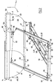
- a dump truck 1 has a cabin before 20, a chassis 3, rolling on the ground by means of wheels 21 supported by axles before 31 and back 32, and a skip 4.
- the bucket 4 has an interior compartment 40 intended to contain materials to be transported, which is delimited by a front wall 41, walls lateral right and left 42 and 43 and a lower wall 44.
- the right and left 42 and 43 and the wall 44 have for example together a semi-cylindrical shape circular from front to back but could also have a flat rectangular shape, to form a front wall and an inner compartment 40 having U-angles or obtuse angles between the bottom wall and the side walls and / or right angles or obtuse angles between the bottom wall and the front wall.
- An unrepresented door can also be provided at the rear of the bucket to open or close the rear opening formed by the walls 42, 43 and 44, or the bucket is free of doors and the rear opening is kept gaping.
- the subframe 5 is fixed on the chassis 3 by appropriate means, for example by bolting.
- the subframe 5 is for example, as well as represented in the figures, of the continuous type from the rear towards the front, comprising two longitudinal right and left longitudinal members 51 and 52 arranged transversely opposite right and left side members 45 and 46 below the bucket 4, so that in position lowered, the longitudinal members 45 and 46 respectively rest on the longitudinal members 51 and 52.
- the longitudinal members 51 and 52 of the subframe 5 support the transverse hinge pin 60 engaged with a lower portion rear 47 of the bucket 4, for example at the rear of its spars 45 and 46.
- the axis 60 articulation is for example formed by a transverse tube fixed to the parts 53 and 54, at the ends of which two rings connected to the rear portion 47 of the skip 4 are mounted rotating.
- One or more bars or side rails 58 can be fixed between the longitudinal members 51 and 52 for their assembly, one for each report to the other. Additional ribs 59 for attachment to the longitudinal members 51 and 52 can be provided at the end of the bars 58.
- these means 9 of lifting and lowering of the bucket are for example formed by two cylinders side 91 and 92 right and left, which are articulated on the one hand by the first axes 93 and 94 on the cross member 8 in FIGS. 1 and 2 or on a support assembly 80 to Figures 3 and 4 and on the other hand, by two right and left axes 95 and 96 on the sides right and left 48 and 49 of the bucket 4.
- the axes 93 and 94 are for example provided at the right and left transverse ends 81 and 82 of the cross member 8 or the assembly 80, and on the lower end of the cylinder barrel, between two cheeks 83, 84 connected at the front for axis 93 at the right end 81 and between two cheeks 85, 86 connected at the front for the axis 94 at the left end 82.
- the axes 95 and 96 are provided at the upper end of the rods of the cylinders, slidably mounted in the barrels.
- the hinge pins 93 and 94 of the cylinders 91 and 92 on the subframe 5 are positioned on it in front of the rear axle (s) 32 of the chassis 3, that is to say in front of the rearmost axle 33 located foremost, and by example at least 1000 millimeters in front of these.
- the rear axle (s) 32 can be defined in this case as being separated from the front axle (s) 31 by a longitudinal distance, which is larger than that separating the front axles 31 between them when several front axles 31 are provided as Figures 1, 3 and 4, and which is larger than that separating the rear axles 32 between them when several rear axles 32 are provided as shown in FIGS. 1, 3 and 4.
- the axes of articulation 95 and 96 of the cylinders 91 and 92 to the bucket 4 are by example also positioned under it, so as to be located, in position lowered of the bucket 4, in front of the axle 32 or rear of the chassis 3, that is to say in front of the rearmost axle 33 located foremost.
- the hinge pins 93 and 94 of the cylinders 91 and 92 on the subframe 5 are positioned thereon closer to the front axle (s) 31 of the chassis 3 than the rear axle (s) 32 of the chassis 3, for example between or above front axles 31 when it has two, or above or between the two front axles 31 located the most backward when more than two front axles 31 are provided.
- the axes 93 and 94 on the one hand and 95 and 96 on the other hand cylinders 91 and 92 are for example aligned transversely for a movement of the cylinders 91 and 92 in a substantially vertical longitudinal plane during lifting and the lowering of the bucket, as is shown.
- the axes of articulation of cylinders 91 and 92 to the subframe 5 and to the bucket 4 can also be non-aligned transversely and the ends of the cylinders located near these axes can be shifted transversely for a displacement of the cylinders in an inclined plane relative to the vertical longitudinal plane when lifting and lowering the tipper, for example so that the axes 93 and 94 are further away from each other than axes 95 and 96.
- the front portion 8 of the subframe serving to support the means 9 lifting and lowering, is by example positioned under the lower front end 50 of the bucket 4, formed by the bottom of its front wall 41 or the front and bottom of its spars 45 and 46.
- the front portion 8 of the subframe, serving to support the lifting means 9 and of lowering is for example at the same height as and in the extension before parts 51, 52 thereof supporting the bucket 4 lowered.
- the bucket 4 lowered then rests also by its lower part before 50 on the part median 87 of this part before 8, the right and left sides 81 and 82 of part 8 then supporting the means 9 lifting and lowering.
- this part median 87 is for example formed by a plate supporting in lowered position the part 50 of the bucket 4, also flat when this part 50 is formed from the front and the bottom of the spars 45 and 46.
- FIG. 3 The embodiment shown in FIG. 3 is described below. and 4, in which the subframe 5 protrudes, from below, from the front of the skip 4 in the lowered position.
- the front portion 8 of the subframe 5 is in front of the end lower front 50 of the bucket 4, formed by the bottom of its front wall 41 or by the front and the bottom of its spars 45 and 46.
- the means 9 for lifting and lowering can be mounted directly on this front part 8 or, as shown in FIGS. 4, on the assembly 80 of support fixed on the upper surface 88c of the front part 8.
- This front portion 8 is no longer formed by a transverse cross member as in Figures 1 and 2, but the front of the longitudinal members 51 and 52 in Figures 3 and 4.
- the assembly 80 is not touched by the bucket 4 and is at a distance from it, including included in the lowered position.
- the assembly 80 is not covered by the bottom of the 4 and is freely accessible, including in a lowered position, where a free space 11 remains above it.
- the support assembly 80 means 9 lifting and lowering is attached to the front of the longitudinal members 51 and 52 for example by members 88a, 88b removable fasteners, which may for example be bolted or sardines, to be independent of the subframe 5. These fasteners 88a, 88b could also be welds. Similarly, mounting members 89a, 89b removable parts can be provided for mounting on the assembly 20 means 9, to know in the example shown in Figures 3 and 4 the axes 93 and 94 of articulation right and left cylinders 91, 92 right and left.
- the support assembly 80 can so be part of a kit ready to be mounted on any type of subframe 5 or frame 3, using the fastening members 88a, 88b and the members 89a, 89b of mounting, provided in this kit or provided on the truck.
- This kit can be used to equip the trucks already equipped with lifting cylinders lifting dump under the bucket, as for example those according to the embodiment of Figures 1 and 2 or those whose jacks are supported near the rear axle (s) or in the middle of these, in the case where these trucks have a sufficient mounting space in front of the bucket and on the front part of their subframe or chassis, to put the fulcrum of the cylinders.
- the support assembly 80 has for example the shape of a housing of beam extending transversely in front of the bucket 4 on the beams 51 and 52. ribs 88d additional fixing to the front portion 8 of the subframe 5 can be provided on the box.
- the means 9 for lifting and lowering act for example, as well as shown in Figures 1 to 4, on the upper right and left sides 71 and 72 of 4. These sides 71 and 72 are for example formed by flanges 711 and 721 right and left walls 42 and 43 of the bucket 4 down and to the right and the left.
- the means 9 for lifting and lowering act for example substantially in the middle, taken from the front to the rear, from the top of the bucket 4, and as shown in Figures 1 and 3.
- the axes 95 and 96 are for example each mounted between a plate 97 extending downwards the flanges 711 and 721 and the wall 42, 43.
- the means 9 for lifting and lowering are located on both right and left sides 48 and 49 of the skip 4.
- the invention is applicable to trucks, trailers, semi-trailers and to those same vehicles equipped with devices with lifting arms, cables or with lifting arm.
Landscapes
- Engineering & Computer Science (AREA)
- Transportation (AREA)
- Mechanical Engineering (AREA)
- Body Structure For Vehicles (AREA)
- Forklifts And Lifting Vehicles (AREA)
Abstract
Description
- la figure 1 représente schématiquement un camion à benne vu de profil du côté gauche et benne abaissée, dans lequel est utilisé un premier mode de réalisation de l'invention,
- la figure 2 représente schématiquement en perspective éclatée le premier mode de réalisation de l'invention du dispositif de montage de la benne suivant la figure 1 en position levée correspondante,
- la figure 3 représente schématiquement un camion à benne vu de profil du côté gauche et benne abaissée, dans lequel est utilisé un deuxième mode de réalisation de l'invention,
- la figure 4 représente schématiquement le deuxième mode de réalisation de l'invention du dispositif de montage de la benne suivant la figure 3 en vue de dessus, dans laquelle la benne et ses moyens de levage n'ont pas été représentés.
Claims (21)
- Dispositif de montage d'une benne (4) sur un châssis (3) roulant, comportant un faux-châssis (5) de repos de la benne (4) en position abaissée, sur lequel sont montées au moins une articulation (60) transversale arrière de la benne (4) entre l'une et l'autre de la position abaissée et d'une position levée vers l'arrière et des moyens (9) de levage et d'abaissement de la benne (4),
caractérisé en ce que
les moyens (9) de levage et d'abaissement sont supportés sur une partie avant (8) du faux-châssis (5), sur deux côtés droit et gauche (81, 82) de celui-ci pour agir sur les côtés droit et gauche (48, 49) de la benne (4). - Dispositif de montage suivant la revendication 1, caractérisé en ce que le faux-châssis (5) comporte au moins une partie (51, 52) pour supporter la benne (4) en position abaissée, autre que l'articulation (60) transversale arrière de la benne (4) et autre que ladite partie avant (8) sur laquelle sont supportés les moyens (9) de levage et d'abaissement.
- Dispositif de montage suivant la revendication 2, caractérisé en ce que ladite partie (51, 52) du faux-châssis (5), qui sert au support de la benne (4) en position abaissée et qui est autre que l'articulation (60) transversale arrière de la benne (4) et autre que la partie avant (8) sur laquelle sont supportés les moyens (9) de levage et d'abaissement, est située entre ladite partie avant (8) et l'articulation (60) transversale arrière de la benne (4).
- Dispositif de montage suivant l'une quelconque des revendications précédentes, caractérisé en ce que les moyens (9) de levage et d'abaissement sont supportés par une traverse (8) transversale formant ladite partie avant du faux-châssis (5).
- Dispositif de montage suivant l'une quelconque des revendications 1 à 3, caractérisé en ce que ladite partie avant (8) du faux-châssis (5), sur laquelle sont supportés les moyens (9) de levage et d'abaissement, est située devant la benne (4).
- Dispositif de montage suivant la revendication 5, caractérisé en ce qu'un ensemble (80) de support des moyens (9) de levage et d'abaissement est fixé sur la surface supérieure (88c) de ladite partie avant (8) du faux-châssis (5).
- Dispositif de montage suivant la revendication 6, caractérisé en ce que l'ensemble (80) de support des moyens (9) de levage et d'abaissement est fixé par des organes (88a, 88b) de fixation amovibles sur la surface supérieure de ladite partie avant (8) du faux-châssis (5), et des organes (89a, 89b) de montage amovibles des moyens (9) de levage et d'abaissement sur l'ensemble (80) de support sont prévus.
- Dispositif de montage suivant la revendication 6 ou 7, caractérisé en ce que l'ensemble (80) de support est formé par un caisson transversal (80), dont les deux côtés droit et gauche (81, 82) supportent les moyens (9) de levage et d'abaissement.
- Dispositif de montage suivant les revendications 7 et 8, caractérisé en ce que l'ensemble (80) de support est un kit.
- Dispositif de montage suivant l'une quelconque des revendications 1 à 4, caractérisé en ce que ladite partie avant du faux-châssis (5) supporte les moyens (9) de levage et d'abaissement et se trouve sous l'extrémité inférieure (50) de la benne (4) en position abaissée.
- Dispositif de montage suivant la revendication 10, caractérisé en ce que la traverse (8) transversale formant ladite partie avant du faux-châssis (5) supporte, par sa partie médiane (87) située entre ses deux côtés droit et gauche (81, 82) supportant les moyens (9) de levage et d'abaissement, une partie inférieure avant (50) de la benne (4) en position abaissée.
- Dispositif de montage suivant l'une quelconque des revendications précédentes, caractérisé en ce que le faux-châssis (5) est continu de l'avant vers l'arrière.
- Dispositif de montage suivant l'une quelconque des revendications précédentes, caractérisé en ce que le faux-châssis (5) comporte deux longerons (51, 52) droit et gauche s'étendant de l'avant vers l'arrière de ladite partie avant (8) à l'articulation (60).
- Dispositif de montage suivant l'une quelconque des revendications précédentes, caractérisé en ce que la benne comporte deux longerons longitudinaux (45, 46) par lesquels la benne (4) repose sur le faux-châssis (5) en position abaissée.
- Dispositif de montage suivant les revendications 13 et 14, caractérisé en ce qu'en position abaissée, les deux longerons longitudinaux droit et gauche (51, 52) du faux-châssis (5) sont disposés transversalement en face des longerons droit et gauche (45, 46) inférieurs de la benne (4), afin qu'en position abaissée, les longerons droit et gauche (45, 46) inférieurs de la benne (4) reposent respectivement sur les longerons longitudinaux droit et gauche (51, 52) du faux-châssis (5).
- Dispositif de montage suivant l'une quelconque des revendications précédentes, caractérisé en ce que la partie avant (8) du faux-châssis, sur laquelle sont supportés les moyens (9) de levage et d'abaissement, est située devant le ou les essieux arrière (32, 33).
- Dispositif de montage suivant l'une quelconque des revendications précédentes, caractérisé en ce que le point d'appui (93, 94) des moyens (9) de levage et d'abaissement sur la benne est situé devant le ou les essieux arrière (32, 33) en position abaissée.
- Dispositif de montage suivant l'une quelconque des revendications précédentes, caractérisé en ce que les moyens (9) de levage et d'abaissement sont formés par deux vérins (91, 92) droit et gauche, articulés d'une part sur la partie avant (8) du faux-châssis et d'autre part sur la benne (4).
- Dispositif de montage suivant l'une quelconque des revendications précédentes, caractérisé en ce que le point d'appui des moyens (9) de levage et d'abaissement sur la benne (4) est situé sur deux côtés supérieurs (71, 72) droit et gauche de celle-ci.
- Dispositif de montage suivant l'une quelconque des revendications précédentes, caractérisé en ce que la partie avant (8) du faux-châssis, sur laquelle sont supportés les moyens (9) de levage et d'abaissement, est située au moins à 1000 millimètres devant le ou les essieux arrière (32, 33).
- Véhicule à benne (4) basculante sur châssis (3) roulant, équipé d'un dispositif de montage de la benne sur le châssis roulant suivant l'une quelconque des revendications précédentes.
Applications Claiming Priority (2)
| Application Number | Priority Date | Filing Date | Title |
|---|---|---|---|
| FR0308873 | 2003-07-21 | ||
| FR0308873A FR2857919B1 (fr) | 2003-07-21 | 2003-07-21 | Dispositif de montage d'une benne et camion muni de celui-ci |
Publications (3)
| Publication Number | Publication Date |
|---|---|
| EP1504953A2 true EP1504953A2 (fr) | 2005-02-09 |
| EP1504953A3 EP1504953A3 (fr) | 2005-06-01 |
| EP1504953B1 EP1504953B1 (fr) | 2013-01-23 |
Family
ID=33548286
Family Applications (1)
| Application Number | Title | Priority Date | Filing Date |
|---|---|---|---|
| EP20040364052 Expired - Lifetime EP1504953B1 (fr) | 2003-07-21 | 2004-07-20 | Dispositif de montage d'une benne et véhicule muni de celui-ci |
Country Status (3)
| Country | Link |
|---|---|
| EP (1) | EP1504953B1 (fr) |
| ES (1) | ES2403147T3 (fr) |
| FR (1) | FR2857919B1 (fr) |
Citations (1)
| Publication number | Priority date | Publication date | Assignee | Title |
|---|---|---|---|---|
| EP1162110A1 (fr) | 2000-06-06 | 2001-12-12 | Forez Bennes Industries (Société Anonyme) | Dispositif d'articulation et de centrage de bennes de camion |
Family Cites Families (4)
| Publication number | Priority date | Publication date | Assignee | Title |
|---|---|---|---|---|
| GB681997A (en) * | 1949-08-08 | 1952-11-05 | Anthony Co | Improvements in and relating to tipping vehicles and the like |
| JPS5529638A (en) * | 1978-08-19 | 1980-03-03 | Kyokuto Kaihatsu Kogyo Co Ltd | Dump truck |
| EP0049482A1 (fr) * | 1980-10-07 | 1982-04-14 | Joseph Chabot | Dispositif de levage d'une benne de camion |
| US6196634B1 (en) * | 1998-11-16 | 2001-03-06 | John Jurinek | Dumping bed liner for pickup truck |
-
2003
- 2003-07-21 FR FR0308873A patent/FR2857919B1/fr not_active Expired - Lifetime
-
2004
- 2004-07-20 EP EP20040364052 patent/EP1504953B1/fr not_active Expired - Lifetime
- 2004-07-20 ES ES04364052T patent/ES2403147T3/es not_active Expired - Lifetime
Patent Citations (1)
| Publication number | Priority date | Publication date | Assignee | Title |
|---|---|---|---|---|
| EP1162110A1 (fr) | 2000-06-06 | 2001-12-12 | Forez Bennes Industries (Société Anonyme) | Dispositif d'articulation et de centrage de bennes de camion |
Also Published As
| Publication number | Publication date |
|---|---|
| FR2857919A1 (fr) | 2005-01-28 |
| ES2403147T3 (es) | 2013-05-14 |
| EP1504953A3 (fr) | 2005-06-01 |
| FR2857919B1 (fr) | 2007-01-05 |
| EP1504953B1 (fr) | 2013-01-23 |
Similar Documents
| Publication | Publication Date | Title |
|---|---|---|
| FR2577862A1 (fr) | Vehicule porteur pour soulever, transporter et deverser, par exemple une poche a crasses | |
| FR3041315A1 (fr) | Systeme d'ouverture de hayon a deux bielettes | |
| EP0749870A1 (fr) | Benne et véhicule la comportant | |
| EP1243464A1 (fr) | Appareil de manutention d'une charge et véhicule le comportant | |
| FR3015420A3 (fr) | ||
| EP1504953B1 (fr) | Dispositif de montage d'une benne et véhicule muni de celui-ci | |
| EP1502811B1 (fr) | Dispositif de montage d'une benne sur un châssis et camion muni de celui-ci | |
| EP2246242B1 (fr) | Remorque pour véhicule automobile comportant une caisse escamotable | |
| FR2710019A1 (fr) | Caisse à parois latérales relevables pour véhicule de transport routier et véhicule équipé d'une telle caisse. | |
| EP1232904A1 (fr) | Véhicule de transport de marchandises à plateforme élévatrice | |
| FR2940937A1 (fr) | Dispositif de support destine a faciliter le chargement d'un caisson ou d'un plateau sur une plate-forme | |
| FR2768974A1 (fr) | Vehicule genre remorque a double basculement | |
| WO2023161475A1 (fr) | Remorque pour le transport d'une charge telle qu'une ou plusieurs palette(s) comprenant un plateau de chargement a surface(s) inclinee(s) | |
| EP3722188B1 (fr) | Camion porteur avec entretoise interposée entre le châssis et la caisse autoportante | |
| FR3037308A1 (fr) | Remorque destinee a etre attelee a un vehicule tracteur et ensemble attele comprenant une telle remorque | |
| FR2693413A1 (fr) | Dispositif pour soulever l'arrière d'une benne par rapport à son chassis. | |
| FR2849009A1 (fr) | Chariot semi-industriel, a portee variable, pour la manutention de materiaux | |
| FR2850619A1 (fr) | Vehicule de transport d'une charge muni d'une barre anti-encastrement | |
| EP1120333B1 (fr) | Col de cygne dépliable pour semi-remorque | |
| EP0171124A1 (fr) | Trappe de chargement et de déchargement destinée particulièrement à une camion pourvu d'un plancher de chargement | |
| EP1445153A2 (fr) | Véhicule équipé d'une barre anti-encastrement rétractable | |
| FR2779706A1 (fr) | Procede et dispositif pour transferer de grands volumes de dechets jusqu'a un emplacement de stockage | |
| FR3167342A1 (fr) | Agencement pour véhicule comprenant une porte de coffre munie d’une traverse arrière. | |
| FR3027276A1 (fr) | Remorque a timon en col de cygne et unite de commande de freinage a inertie, et ensemble routier la comprenant | |
| FR3112020A1 (fr) | Systeme de support d’emballage de transport de matieres radioactives, configure pour permettre son basculement d’une position horizontale de transport a une position verticale d’exploitation |
Legal Events
| Date | Code | Title | Description |
|---|---|---|---|
| PUAI | Public reference made under article 153(3) epc to a published international application that has entered the european phase |
Free format text: ORIGINAL CODE: 0009012 |
|
| AK | Designated contracting states |
Kind code of ref document: A2 Designated state(s): AT BE BG CH CY CZ DE DK EE ES FI FR GB GR HU IE IT LI LU MC NL PL PT RO SE SI SK TR |
|
| AX | Request for extension of the european patent |
Extension state: AL HR LT LV MK |
|
| PUAL | Search report despatched |
Free format text: ORIGINAL CODE: 0009013 |
|
| AK | Designated contracting states |
Kind code of ref document: A3 Designated state(s): AT BE BG CH CY CZ DE DK EE ES FI FR GB GR HU IE IT LI LU MC NL PL PT RO SE SI SK TR |
|
| AX | Request for extension of the european patent |
Extension state: AL HR LT LV MK |
|
| 17P | Request for examination filed |
Effective date: 20051031 |
|
| AKX | Designation fees paid |
Designated state(s): AT BE BG CH CY CZ DE DK EE ES FI FR GB GR HU IE IT LI LU MC NL PL PT RO SE SI SK TR |
|
| 17Q | First examination report despatched |
Effective date: 20051219 |
|
| 19U | Interruption of proceedings before grant |
Effective date: 20071221 |
|
| 19W | Proceedings resumed before grant after interruption of proceedings |
Effective date: 20120601 |
|
| RAP1 | Party data changed (applicant data changed or rights of an application transferred) |
Owner name: C.I. 85 |
|
| RIN1 | Information on inventor provided before grant (corrected) |
Inventor name: SAUVION, JEAN-PIERRE |
|
| GRAP | Despatch of communication of intention to grant a patent |
Free format text: ORIGINAL CODE: EPIDOSNIGR1 |
|
| RIN1 | Information on inventor provided before grant (corrected) |
Inventor name: SAUVION, JEAN-PIERRE |
|
| GRAS | Grant fee paid |
Free format text: ORIGINAL CODE: EPIDOSNIGR3 |
|
| GRAA | (expected) grant |
Free format text: ORIGINAL CODE: 0009210 |
|
| AK | Designated contracting states |
Kind code of ref document: B1 Designated state(s): AT BE BG CH CY CZ DE DK EE ES FI FR GB GR HU IE IT LI LU MC NL PL PT RO SE SI SK TR |
|
| REG | Reference to a national code |
Ref country code: GB Ref legal event code: FG4D Free format text: NOT ENGLISH |
|
| REG | Reference to a national code |
Ref country code: CH Ref legal event code: EP |
|
| REG | Reference to a national code |
Ref country code: AT Ref legal event code: REF Ref document number: 594768 Country of ref document: AT Kind code of ref document: T Effective date: 20130215 Ref country code: CH Ref legal event code: EP |
|
| REG | Reference to a national code |
Ref country code: IE Ref legal event code: FG4D Free format text: LANGUAGE OF EP DOCUMENT: FRENCH |
|
| REG | Reference to a national code |
Ref country code: DE Ref legal event code: R096 Ref document number: 602004040848 Country of ref document: DE Effective date: 20130321 |
|
| REG | Reference to a national code |
Ref country code: RO Ref legal event code: EPE |
|
| REG | Reference to a national code |
Ref country code: ES Ref legal event code: FG2A Ref document number: 2403147 Country of ref document: ES Kind code of ref document: T3 Effective date: 20130514 |
|
| REG | Reference to a national code |
Ref country code: AT Ref legal event code: MK05 Ref document number: 594768 Country of ref document: AT Kind code of ref document: T Effective date: 20130123 |
|
| REG | Reference to a national code |
Ref country code: NL Ref legal event code: VDEP Effective date: 20130123 |
|
| PG25 | Lapsed in a contracting state [announced via postgrant information from national office to epo] |
Ref country code: AT Free format text: LAPSE BECAUSE OF FAILURE TO SUBMIT A TRANSLATION OF THE DESCRIPTION OR TO PAY THE FEE WITHIN THE PRESCRIBED TIME-LIMIT Effective date: 20130123 Ref country code: CY Free format text: LAPSE BECAUSE OF FAILURE TO SUBMIT A TRANSLATION OF THE DESCRIPTION OR TO PAY THE FEE WITHIN THE PRESCRIBED TIME-LIMIT Effective date: 20130123 Ref country code: SE Free format text: LAPSE BECAUSE OF FAILURE TO SUBMIT A TRANSLATION OF THE DESCRIPTION OR TO PAY THE FEE WITHIN THE PRESCRIBED TIME-LIMIT Effective date: 20130123 |
|
| PG25 | Lapsed in a contracting state [announced via postgrant information from national office to epo] |
Ref country code: PL Free format text: LAPSE BECAUSE OF FAILURE TO SUBMIT A TRANSLATION OF THE DESCRIPTION OR TO PAY THE FEE WITHIN THE PRESCRIBED TIME-LIMIT Effective date: 20130123 Ref country code: GR Free format text: LAPSE BECAUSE OF FAILURE TO SUBMIT A TRANSLATION OF THE DESCRIPTION OR TO PAY THE FEE WITHIN THE PRESCRIBED TIME-LIMIT Effective date: 20130424 Ref country code: NL Free format text: LAPSE BECAUSE OF FAILURE TO SUBMIT A TRANSLATION OF THE DESCRIPTION OR TO PAY THE FEE WITHIN THE PRESCRIBED TIME-LIMIT Effective date: 20130123 Ref country code: FI Free format text: LAPSE BECAUSE OF FAILURE TO SUBMIT A TRANSLATION OF THE DESCRIPTION OR TO PAY THE FEE WITHIN THE PRESCRIBED TIME-LIMIT Effective date: 20130123 Ref country code: PT Free format text: LAPSE BECAUSE OF FAILURE TO SUBMIT A TRANSLATION OF THE DESCRIPTION OR TO PAY THE FEE WITHIN THE PRESCRIBED TIME-LIMIT Effective date: 20130523 Ref country code: SI Free format text: LAPSE BECAUSE OF FAILURE TO SUBMIT A TRANSLATION OF THE DESCRIPTION OR TO PAY THE FEE WITHIN THE PRESCRIBED TIME-LIMIT Effective date: 20130123 |
|
| PG25 | Lapsed in a contracting state [announced via postgrant information from national office to epo] |
Ref country code: CZ Free format text: LAPSE BECAUSE OF FAILURE TO SUBMIT A TRANSLATION OF THE DESCRIPTION OR TO PAY THE FEE WITHIN THE PRESCRIBED TIME-LIMIT Effective date: 20130123 Ref country code: EE Free format text: LAPSE BECAUSE OF FAILURE TO SUBMIT A TRANSLATION OF THE DESCRIPTION OR TO PAY THE FEE WITHIN THE PRESCRIBED TIME-LIMIT Effective date: 20130123 Ref country code: SK Free format text: LAPSE BECAUSE OF FAILURE TO SUBMIT A TRANSLATION OF THE DESCRIPTION OR TO PAY THE FEE WITHIN THE PRESCRIBED TIME-LIMIT Effective date: 20130123 Ref country code: DK Free format text: LAPSE BECAUSE OF FAILURE TO SUBMIT A TRANSLATION OF THE DESCRIPTION OR TO PAY THE FEE WITHIN THE PRESCRIBED TIME-LIMIT Effective date: 20130123 |
|
| PLBE | No opposition filed within time limit |
Free format text: ORIGINAL CODE: 0009261 |
|
| STAA | Information on the status of an ep patent application or granted ep patent |
Free format text: STATUS: NO OPPOSITION FILED WITHIN TIME LIMIT |
|
| PG25 | Lapsed in a contracting state [announced via postgrant information from national office to epo] |
Ref country code: IT Free format text: LAPSE BECAUSE OF FAILURE TO SUBMIT A TRANSLATION OF THE DESCRIPTION OR TO PAY THE FEE WITHIN THE PRESCRIBED TIME-LIMIT Effective date: 20130123 |
|
| 26N | No opposition filed |
Effective date: 20131024 |
|
| BERE | Be: lapsed |
Owner name: C.I. 85 Effective date: 20130731 |
|
| REG | Reference to a national code |
Ref country code: DE Ref legal event code: R097 Ref document number: 602004040848 Country of ref document: DE Effective date: 20131024 |
|
| PG25 | Lapsed in a contracting state [announced via postgrant information from national office to epo] |
Ref country code: MC Free format text: LAPSE BECAUSE OF FAILURE TO SUBMIT A TRANSLATION OF THE DESCRIPTION OR TO PAY THE FEE WITHIN THE PRESCRIBED TIME-LIMIT Effective date: 20130123 |
|
| REG | Reference to a national code |
Ref country code: IE Ref legal event code: MM4A |
|
| PG25 | Lapsed in a contracting state [announced via postgrant information from national office to epo] |
Ref country code: BE Free format text: LAPSE BECAUSE OF NON-PAYMENT OF DUE FEES Effective date: 20130731 |
|
| PG25 | Lapsed in a contracting state [announced via postgrant information from national office to epo] |
Ref country code: IE Free format text: LAPSE BECAUSE OF NON-PAYMENT OF DUE FEES Effective date: 20130720 |
|
| PG25 | Lapsed in a contracting state [announced via postgrant information from national office to epo] |
Ref country code: TR Free format text: LAPSE BECAUSE OF FAILURE TO SUBMIT A TRANSLATION OF THE DESCRIPTION OR TO PAY THE FEE WITHIN THE PRESCRIBED TIME-LIMIT Effective date: 20130123 |
|
| PG25 | Lapsed in a contracting state [announced via postgrant information from national office to epo] |
Ref country code: HU Free format text: LAPSE BECAUSE OF FAILURE TO SUBMIT A TRANSLATION OF THE DESCRIPTION OR TO PAY THE FEE WITHIN THE PRESCRIBED TIME-LIMIT; INVALID AB INITIO Effective date: 20040720 Ref country code: LU Free format text: LAPSE BECAUSE OF NON-PAYMENT OF DUE FEES Effective date: 20130720 |
|
| REG | Reference to a national code |
Ref country code: FR Ref legal event code: PLFP Year of fee payment: 13 |
|
| REG | Reference to a national code |
Ref country code: FR Ref legal event code: PLFP Year of fee payment: 14 |
|
| PGFP | Annual fee paid to national office [announced via postgrant information from national office to epo] |
Ref country code: CZ Payment date: 20170316 Year of fee payment: 6 Ref country code: ES Payment date: 20170810 Year of fee payment: 14 Ref country code: RO Payment date: 20170718 Year of fee payment: 14 Ref country code: DE Payment date: 20170731 Year of fee payment: 14 |
|
| PGFP | Annual fee paid to national office [announced via postgrant information from national office to epo] |
Ref country code: BG Payment date: 20170719 Year of fee payment: 14 |
|
| REG | Reference to a national code |
Ref country code: FR Ref legal event code: PLFP Year of fee payment: 15 |
|
| REG | Reference to a national code |
Ref country code: DE Ref legal event code: R119 Ref document number: 602004040848 Country of ref document: DE |
|
| GBPC | Gb: european patent ceased through non-payment of renewal fee |
Effective date: 20180720 |
|
| PG25 | Lapsed in a contracting state [announced via postgrant information from national office to epo] |
Ref country code: DE Free format text: LAPSE BECAUSE OF NON-PAYMENT OF DUE FEES Effective date: 20190201 Ref country code: RO Free format text: LAPSE BECAUSE OF NON-PAYMENT OF DUE FEES Effective date: 20180720 Ref country code: GB Free format text: LAPSE BECAUSE OF NON-PAYMENT OF DUE FEES Effective date: 20180720 |
|
| PG25 | Lapsed in a contracting state [announced via postgrant information from national office to epo] |
Ref country code: BG Free format text: LAPSE BECAUSE OF NON-PAYMENT OF DUE FEES Effective date: 20190430 |
|
| REG | Reference to a national code |
Ref country code: ES Ref legal event code: FD2A Effective date: 20190917 |
|
| PG25 | Lapsed in a contracting state [announced via postgrant information from national office to epo] |
Ref country code: ES Free format text: LAPSE BECAUSE OF NON-PAYMENT OF DUE FEES Effective date: 20180721 |
|
| PGFP | Annual fee paid to national office [announced via postgrant information from national office to epo] |
Ref country code: CH Payment date: 20190724 Year of fee payment: 16 |
|
| REG | Reference to a national code |
Ref country code: CH Ref legal event code: PL |
|
| PG25 | Lapsed in a contracting state [announced via postgrant information from national office to epo] |
Ref country code: LI Free format text: LAPSE BECAUSE OF NON-PAYMENT OF DUE FEES Effective date: 20200731 Ref country code: CH Free format text: LAPSE BECAUSE OF NON-PAYMENT OF DUE FEES Effective date: 20200731 |
|
| PGFP | Annual fee paid to national office [announced via postgrant information from national office to epo] |
Ref country code: FR Payment date: 20230727 Year of fee payment: 20 |