EP1504973A2 - Gicleur de lave-glace pour véhicule et dispositif lave-glace pour véhicule ayant une structure régulant la diffusion - Google Patents
Gicleur de lave-glace pour véhicule et dispositif lave-glace pour véhicule ayant une structure régulant la diffusion Download PDFInfo
- Publication number
- EP1504973A2 EP1504973A2 EP04018734A EP04018734A EP1504973A2 EP 1504973 A2 EP1504973 A2 EP 1504973A2 EP 04018734 A EP04018734 A EP 04018734A EP 04018734 A EP04018734 A EP 04018734A EP 1504973 A2 EP1504973 A2 EP 1504973A2
- Authority
- EP
- European Patent Office
- Prior art keywords
- nozzle
- diffusive
- vehicle
- tip
- washer
- Prior art date
- Legal status (The legal status is an assumption and is not a legal conclusion. Google has not performed a legal analysis and makes no representation as to the accuracy of the status listed.)
- Granted
Links
Images


Classifications
-
- B—PERFORMING OPERATIONS; TRANSPORTING
- B60—VEHICLES IN GENERAL
- B60S—SERVICING, CLEANING, REPAIRING, SUPPORTING, LIFTING, OR MANOEUVRING OF VEHICLES, NOT OTHERWISE PROVIDED FOR
- B60S1/00—Cleaning of vehicles
- B60S1/02—Cleaning windscreens, windows or optical devices
- B60S1/46—Cleaning windscreens, windows or optical devices using liquid; Windscreen washers
- B60S1/48—Liquid supply therefor
- B60S1/52—Arrangement of nozzles; Liquid spreading means
-
- B—PERFORMING OPERATIONS; TRANSPORTING
- B05—SPRAYING OR ATOMISING IN GENERAL; APPLYING FLUENT MATERIALS TO SURFACES, IN GENERAL
- B05B—SPRAYING APPARATUS; ATOMISING APPARATUS; NOZZLES
- B05B1/00—Nozzles, spray heads or other outlets, with or without auxiliary devices such as valves, heating means
- B05B1/02—Nozzles, spray heads or other outlets, with or without auxiliary devices such as valves, heating means designed to produce a jet, spray, or other discharge of particular shape or nature, e.g. in single drops, or having an outlet of particular shape
-
- B—PERFORMING OPERATIONS; TRANSPORTING
- B05—SPRAYING OR ATOMISING IN GENERAL; APPLYING FLUENT MATERIALS TO SURFACES, IN GENERAL
- B05B—SPRAYING APPARATUS; ATOMISING APPARATUS; NOZZLES
- B05B1/00—Nozzles, spray heads or other outlets, with or without auxiliary devices such as valves, heating means
- B05B1/02—Nozzles, spray heads or other outlets, with or without auxiliary devices such as valves, heating means designed to produce a jet, spray, or other discharge of particular shape or nature, e.g. in single drops, or having an outlet of particular shape
- B05B1/08—Nozzles, spray heads or other outlets, with or without auxiliary devices such as valves, heating means designed to produce a jet, spray, or other discharge of particular shape or nature, e.g. in single drops, or having an outlet of particular shape of pulsating nature, e.g. delivering liquid in successive separate quantities
-
- B—PERFORMING OPERATIONS; TRANSPORTING
- B05—SPRAYING OR ATOMISING IN GENERAL; APPLYING FLUENT MATERIALS TO SURFACES, IN GENERAL
- B05B—SPRAYING APPARATUS; ATOMISING APPARATUS; NOZZLES
- B05B1/00—Nozzles, spray heads or other outlets, with or without auxiliary devices such as valves, heating means
- B05B1/02—Nozzles, spray heads or other outlets, with or without auxiliary devices such as valves, heating means designed to produce a jet, spray, or other discharge of particular shape or nature, e.g. in single drops, or having an outlet of particular shape
- B05B1/10—Nozzles, spray heads or other outlets, with or without auxiliary devices such as valves, heating means designed to produce a jet, spray, or other discharge of particular shape or nature, e.g. in single drops, or having an outlet of particular shape in the form of a fine jet, e.g. for use in wind-screen washers
Definitions
- the present invention relates to a vehicular washer nozzle that jets cleansing liquid to wash a windshield of a vehicle, and a vehicular washer device that is provided with a washer nozzle to wash a windshield of a vehicle.
- a washer device is constructed such that pressure-fed cleansing liquid is jetted toward a windshield.
- the washer nozzle is fixed to project above an engine hood of a vehicle, so that an outward appearance is degraded in terms of vehicular design.
- a vehicle body gets dirt when the cleansing liquid remaining in a hose drips from the washer nozzle.
- JP-A-10-236283 In order to remedy a disadvantage of the washer device (washer nozzle) shown in JP-A-10-236283, another structure is proposed in JP-A-2000-344062, in which a washer nozzle is provided on an underside of a rear portion of an engine hood of a vehicle,
- wiper arms are arranged lengthwise along a widthwise direction of the vehicle, when a wiper device is stopped (in a stopped position) and a rear end edge of the engine hood comes out. Accordingly, when cleansing liquid is jetted toward a windshield from the washer nozzle, the jetted cleansing liquid may interfere with the wiper arms and the rear end edge of the engine hood, and scattered wastefully.
- the diffusion jet nozzle makes use of a fluid element (nozzle tip) to feed back a part of diffusive flow to cause self-oscillation of the same as a control flow, whereby a flow is jetted from the washer nozzle as diffusive flow spreading in a widthwise direction of the vehicle. That is, diffusive flow jetted from such a diffusion jet nozzle is not concentrated like jet flow, but water droplets of a small particle size are spread and jetted in the widthwise direction of the vehicle. The diffusive flow is also spread in a heightwise direction of the vehicle. Accordingly, it is difficult to sprinkle the diffusion jet flow on a desired sprinkle point from a narrow gap between the wiper arms and the rear end edge of the engine hood without interference.
- a vehicular washer nozzle (vehicular washer devices) capable of sprinkling a diffused jet flow over a wide range in a widthwise direction of the vehicle and furthermore sprinkling the diffused jet flow on a target sprinkle point from a narrow gap between wiper arms and a rear end edge of an engine hood without interference.
- a vehicular washer device has a washer nozzle arranged on a back surface side of a rear end edge of an engine hood of a vehicle to jet pressure-fed cleansing liquid toward a windshield.
- the vehicular washer nozzle includes a nozzle body, a nozzle tip, a diffusion restriction portion, and a mount opening.
- the nozzle body is fixed to the vehicle, and formed with a feed passage through which the pressure-fed cleansing liquid is guided and fed.
- the nozzle tip is integrally assembled fluid-tightly to a receiving portion formed in the nozzle body.
- the nozzle tip defines an oscillation chamber and a diffusive jet port. The oscillation chamber communicates to the feed passage to cause self-oscillation of the cleansing liquid fed from the feed passage.
- the diffusive jet port communicates to the oscillation chamber to jet the cleansing liquid as a diffusive flow diffused in a widthwise direction of the vehicle.
- the diffusion restriction portion is provided on the nozzle body to outwardly open along a direction, in which a diffusive flow is jetted from the diffusive jet port.
- the diffusion restriction portion restricts and regulates the diffusive flow jetted from the diffusive jet port in a vertical direction of the vehicle, when the nozzle tip is assembled to the receiving portion of the nozzle body.
- the mount opening communicates to the receiving portion of the nozzle body and opens in a different direction than one direction, in which the diffusion restriction portion opens. The nozzle tip is assembled to the receiving portion through the mount opening.
- a washer device X includes a washer nozzle 10 that has a nozzle body 12 and a nozzle tip 14.
- the nozzle body 12 is made of a resinous material, and formed on the upper surface side thereof with an elastic latch piece 16 and on the lower surface side thereof with a latch pawl 18.
- the elastic latch piece 16 and the latch pawl 18 are fitted into a back-side panel P on a rear end edge of an engine hood F of a vehicle to fix and arrange the nozzle body 12.
- a cylindrical-shaped hose connection 20 is formed at a rear end of the nozzle body 12 to be connected with a hose 22 that is connected to cleansing liquid containing tank (not shown).
- the nozzle body 12 is formed with a tip receiving portion 24 that is opened to a front surface side (a side of a windshield G in Figs. 1 and 2) of the nozzle body 12.
- a feed passage 26 is formed contiguous to the tip receiving portion 24 of the nozzle body 12. One end of the feed passage 26 extends to the hose connection 20.
- the nozzle tip 14 formed by resin molding is integrally and fluid-tightly fitted into the tip receiving portion 24 of the nozzle body 12.
- the nozzle tip 14 is formed to be substantially box-shaped, and inserted into the tip receiving portion 24 of the nozzle body 12 from a front opened side thereof to be assembled thereto.
- the nozzle tip 14 is formed with a flow passage 28 (forming a part of the feed passage 26) that is communicated to the feed passage 26 in a state of being fitted into the tip receiving portion 24 of the nozzle body 12.
- an oscillation chamber 30 and a diffusive jet port 32 are formed on the lower side (lower side in Figs. 1 to 3) of the nozzle tip 14.
- the oscillation chamber 30 is formed with a main flow passage 34, which is contiguous to the flow passage 28 and communicated to the diffusive jet port 32, and a pair of feedback flow passages 36 that substantially horizontally branch left and right from the main flow passage 34.
- Cleansing liquid is supplied to the oscillation chamber 30 from the flow passage 28.
- the feedback flow passages 36 are formed such that a part of the cleansing liquid fed from the flow passage 28 is divided and guided at this time to be returned to the main flow passage 34. Thereby, the cleansing liquid guided to the feedback flow passages 36 makes a "control flow" to cause self-oscillation of the cleansing liquid flowing in the main flow passage 34.
- the cleansing liquid causing the self-oscillation is jetted as a sector-shaped diffusive flow from the diffusive jet port 32. Accordingly, the cleansing liquid can be jetted over a comparatively wide range in a widthwise direction of the vehicle to increase an area being cleansed.
- the nozzle tip 14 is formed with an upper correction plate portion 38 that serves as a diffusion restriction portion.
- the upper correction plate portion 38 is integrally formed to extend from immediately above the diffusive jet port 32, i.e., a bottom wall portion opposed to an opening surface 31 of the oscillation chamber 30.
- the upper correction plate portion 38 is provided along a jet direction of diffusive flow jetted from the diffusive jet port 32.
- the upper correction plate portion 38 is opposed immediately backwardly of the diffusive jet port 32 to an opening lower wall surface 40 (Fig. 2) in a front opened portion of the tip receiving portion 24 of the nozzle body 12.
- the flat-shaped upper correction plate portion 38 and the opening lower wall surface 40 which extend continuously over the nozzle tip 14 in its widthwise direction, form the diffusion restriction portion.
- the diffusion restriction portion formed by the upper correction plate portion 38 and the opening lower wall surface 40 is opened outside along a target jet direction L1 of the diffusive flow jetted from the diffusive jet port 32.
- the upper correction plate portion 38 restricts and regulates an upward diffusion of diffusive flow jetted from the diffusive jet port 32
- the opening lower wall surface 40 restricts and regulates a downward diffusion of diffusive flow jetted from the diffusive jet port 32.
- the upper correction plate portion 38 of the nozzle tip 14 and the opening lower wall surface 40 of the tip receiving portion 24 of the nozzle body 12 cooperate together to restrict and regulate diffusion of diffusive flow jetted from the diffusive jet port 32, in the vertical direction of the vehicle.
- the vertical direction of the vehicle is perpendicular to a direction of diffusion.
- the target jet direction L1 of the diffusive flow which is regulated by the upper correction plate portion 38 and the opening lower wall surface 40, becomes coincident (coaxial) with a direction, in which the nozzle tip 14 is inserted into and assembled to the tip receiving portion 24 of the nozzle body 12. That is, the target jet direction L1 of the diffusive flow becomes parallel to the bottom wall surface of the oscillation chamber 30.
- the diffusive jet port 32 is a "fluidics type nozzle". Cleansing liquid is jetted as diffusive flow from the diffusive jet port 32, and the diffusion restriction portion formed by the upper correction plate portion 38 and the opening lower wall surface 40 restricts and regulates a vertical diffusion of the diffusive flow to enable diffusively jetting the diffusive flow.
- the washer nozzle 10 is arranged on a back surface side of a rear end edge of the engine hood F of a vehicle.
- Cleansing liquid pressure-fed from the tank passes through the hose connection 20 and the feed passage 26 of the nozzle body 12, and flows into the oscillation chamber 30 of the nozzle tip 14 after passing through the flow passage 28.
- a part of the cleansing liquid fed from the flow passage 28 is divided by the feedback flow passages 36 to be returned to the main flow passage 34.
- the cleansing liquid guided to the feedback flow passages 36 makes a control flow to cause self-oscillation of the cleansing liquid flowing in the main flow passage 34.
- the cleansing liquid occurring self-oscillation becomes water droplets of a small particle size to be jetted as a sector-shaped diffusive flow in the widthwise direction of the vehicle from the diffusive jet port 32.
- the diffusion restriction portion is opened outside along the jet direction of diffusive flow jetted from the diffusive jet port 32.
- the diffusive flow jetted from the diffusive jet port 32 is restricted in diffusion in the vertical direction of the vehicle by the upper correction plate portion 38 and the opening lower wall surface 40 to be regulated.
- the vertical direction of the vehicle is the direction perpendicular to the direction of diffusion of the cleansing liquid.
- the diffusion restriction portion is constructed with the upper correction plate portion 38 of the nozzle tip 14 and the opening lower wall surface 40 of the tip receiving portion 24 of the nozzle body 12.
- the diffusive flow jetted from the diffusive jet port 32 can be sprinkled over a wide range in the widthwise direction of the vehicle.
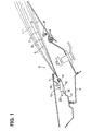
- the diffusive flow can be sprinkled on a target sprinkle point of the windshield G from a narrow gap between the wiper arms W and the rear end edge of the engine hood F as shown by broken lines A, alternate long and short dash lines B, and solid lines C in Fig. 1 without interference.
- a jet range indicated by the broken lines A defines an upper limit range.
- a jet range indicated by the alternate long and short dash lines B defines a lower limit range.
- a jet range indicated by the solid lines C defines a target jet range, and the straight line L1 indicates a target jet direction, in which sprinkling in the target jet range is performed.
- the washer nozzle 10 is arranged on the back surface side of the rear end edge of the engine hood F of a vehicle, surfaces of a vehicle body do not get dirt even when cleansing liquid remaining in the hose 22 drips, for example.
- the hose 22 supplies cleansing liquid.
- a vehicle is improved in design quality.
- the oscillation chamber 30 having a complex shape relative to the diffusive jet port 32 is formed to be opened to an underside of the nozzle tip 14.
- the upper correction plate portion 38 constructing the diffusion restriction portion is integrally formed to extend from the bottom wall portion of the nozzle tip 14 opposed to the opening surface 31 of the oscillation chamber 30. Therefore, the upper correction plate portion 38 may be in a simple shape, in which the bottom wall portion of the nozzle tip 14 is extended in a manner like a pent roof. Accordingly, when the nozzle tip 14 is molded from a resinous material, a molding die can be in a simple shape.
- the feed passage 26 of the nozzle body 12 is formed to be communicated linearly to the flow passage 28 of the nozzle tip 14, in this embodiment.
- a feed passage 44 may be communicated to an underside of the oscillation chamber 30 of the nozzle tip 14 in a washer nozzle 42 shown in Fig. 6.
- a washer nozzle 50 has a nozzle body 52 and a nozzle tip 54.
- the nozzle body 52 has the substantially same structure as that of the nozzle body 12 of the washer nozzle 10 described in the first embodiment, and accommodates a nozzle tip 54 in a tip receiving portion 24 thereof.
- the nozzle tip 54 is formed with an oscillation chamber 30 and a diffusive jet port 32 on the underside (lower side in Fig. 7) thereof.
- the nozzle tip 54 is formed with an upper correction plate portion 56 and a lower correction plate portion 58, which form a diffusion restriction portion.
- the upper correction plate portion 56 forming the diffusion restriction portion is integrally formed to extend from immediately above a diffusive jet port 32. That is, the upper correction plate portion 56 is integrally formed to extend from a bottom wall portion opposed to an opening surface 31 of the oscillation chamber 30, and provided along a jet direction of diffusive flow jetted from the diffusive jet port 32.
- the lower correction plate portion 58 forming the diffusion restriction portion is integrally formed to extend from immediately below the diffusive jet port 32.
- the lower correction plate portion 58 is integrally formed to extend from a wall portion on a side of the opening surface 31 of the oscillation chamber 30, and provided along the jet direction of diffusive flow jetted from the diffusive jet port 32.
- the upper correction plate portion 56 and the lower correction plate portion 58 face each other in a parallel state immediately backwardly of the diffusive jet port 32.
- the upper correction plate portion 56 and the lower correction plate portion 58 form the diffusion restriction portion.
- the diffusion restriction portion formed with the upper correction plate portion 56 and the lower correction plate portion 58 is provided to be opened outside along the jet direction of diffusive flow jetted from the diffusive jet port 32.
- the upper correction plate portion 56 restricts and regulates an upward diffusion of diffusive flow jetted from the diffusive jet port 32
- the lower correction plate portion 58 restricts and regulates an downward diffusion of diffusive flow jetted from the diffusive jet port 32. That is, the upper correction plate portion 56 and the lower correction plate portion 58 of the nozzle tip 54 cooperate together to restrict and regulate diffusion, in the vertical direction of the vehicle, of diffusive flow jetted from the diffusive jet port 32.
- the upper correction plate portion 56 and the lower correction plate portion 58 are inclined upward at a predetermined angle relative to a direction, in which the nozzle tip 54 is inserted into and assembled to the tip receiving portion 24 of the nozzle body 12. That is, an axis of a regulated diffusive flow in its jet direction is directed upward at a predetermined angle relative to the bottom wall surface of the oscillation chamber 30. Therefore, target jet can be set in the vertical direction of the vehicle, which is different from the direction, in which the nozzle tip 54 is inserted into and assembled to the tip receiving portion 24 of the nozzle body 12.
- the diffusive jet port 32 has a structure of a "fluidics type nozzle".
- cleansing liquid is jetted as diffusive flow from the diffusive jet port 32.
- the diffusion restriction portion formed by the upper correction plate portion 56 and the lower correction plate portion 58 of the nozzle tip 54 restricts and regulates diffusion of the diffusive flow in the vertical direction of the vehicle to enable diffusively jetting the diffusive flow.
- the diffusion restriction portion is formed by the upper correction plate portion 56 and the lower correction plate portion 58, which are formed to extend integrally from the nozzle tip 54. Accordingly, the diffusion restriction portion can be formed by only the nozzle tip 54 without depending on the nozzle body 52. Therefore, the nozzle body 52 can be commonly used for different nozzle tips 54. Besides, an action of regulation, in which diffusion of diffusive flow in the vertical direction of the vehicle is restricted by the upper correction plate portion 56 and the lower correction plate portion 58. Furthermore, a jet angle (direction) can be set with high accuracy without being affected by the assembling accuracy of the nozzle tip 54. Here, the vertical direction of the vehicle is perpendicular to the direction of diffusion.
- the upper correction plate portion 56 and the lower correction plate portion 58 are provided to be inclined upward at a predetermined angle and an axis of a regulated diffusive flow in its jet direction is directed upward at a predetermined angle. Therefore, setting of a jet angle can be easily modified every vehicle or every type of vehicle by making a shape of the oscillation chamber 30 common for different nozzle tips 54, that is, by setting only the upper correction plate portion 56 and the lower correction plate portion 58 in a different manner.
- the oscillation chamber 30 is a fundamental constituent portion (important constituent portion) of the nozzle tip 54.
- the upper correction plate portion 56 and the lower correction plate portion 58 face each other in a parallel state immediately backwardly of the diffusive jet port 32.
- the upper correction plate portion 56 and the lower correction plate portion 58 may be shaped vertically small, so that a passage is gradually made convergent in height toward a tip end side (side of the outside opening) from the diffusive jet port 32.
- a vertical extent of a jetted diffusive flow can be further corrected, and jet pressure of diffusive flow jetted from the diffusive jet port 32 can be suitably raised, so that jet can be efficiently achieved.
- a washer nozzle 60 has a nozzle body 62 and a nozzle tip 64.
- the nozzle body 62 has a fundamentally the same structure as that of the nozzle body 12 of the washer nozzle 10 described in the first embodiment, and accommodates a nozzle tip 64 in a tip receiving portion 66.
- the tip receiving portion 66 of the nozzle body 62 is opened to a right side (front side of the plane of Fig. 8) of the nozzle body 62, and the opening forms a mount opening 68, through which the nozzle tip 64 is assembled to the tip receiving portion 66 of the nozzle body 62.
- the nozzle tip 64 has fundamentally the same structure as that of the nozzle tip 14 of the washer nozzle 10 according to the first embodiment, and the nozzle tip 64 is formed with an oscillation chamber 30 and a diffusive jet port 32.
- the nozzle tip 64 (Fig. 9) is provided in a corner on a rear end side thereof with a chamfer 70.
- the chamfer 70 serves as a confirmation portion of orientation of the nozzle tip 64 and can prevent the nozzle tip 64 from wrong assembling.
- a passage 72 is formed in a front part (right side in Fig. 8) of the nozzle body 62.
- the passage 72 is formed to be opened outside along a direction, in which diffusive flow from the diffusive jet port 32 is jetted, when the nozzle tip 64 is assembled to the tip receiving portion 66 of the nozzle body 62.
- upper and lower opening wall surface portions 74 of the passage 72 form a diffusion restriction portion. That is, when the nozzle tip 64 is assembled to the tip receiving portion 66 of the nozzle body 62, the pair of upper and lower opening wall surface portions 74, which form the diffusion restriction portion, extend contiguous to upper and lower end edges of the diffusive jet port 32, and face each other in a parallel state.
- the pair of upper and lower opening wall surface portions 74 extend along a direction, in which diffusive flow from the diffusive jet port 32 is jetted, to restrict and regulate diffusion of diffusive flow jetted from the diffusive jet port 32 in the vertical direction of the vehicle.
- an axis of diffusive flow regulated by the pair of upper and lower opening wall surface portions 74 in its jet direction is made coincident (coaxial) with the bottom wall surface of the oscillation chamber 30 of the nozzle tip 64, when the nozzle tip 64 is assembled to the tip receiving portion 66 of the nozzle body 62.
- the washer nozzle 60 (washer device, to which the washer nozzle 60 is applied) constructed in the above manner, the washer nozzle 60 is arranged on a back surface side of a rear end edge of an engine hood F of a vehicle.
- Cleansing liquid is pressure-fed from the tank into the oscillation chamber 30 of the nozzle tip 64 through a hose connection 20 of the nozzle body 62.
- a part of the cleansing liquid fed from a flow passage 28 is divided and guided by feedback flow passages 36 to be returned to a main flow passage 34.
- the cleansing liquid guided to the feedback flow passages 36 makes a control flow to cause self-oscillation of the cleansing liquid flowing in the main flow passage 34.
- the cleansing liquid causing self-oscillation is made water droplets of a small particle size to be jetted as a sector-shaped diffusive flow in the widthwise direction of the vehicle from the diffusive jet port 32.
- the pair of upper and lower opening wall surface portions 74 of the passage 72 are provided to extend contiguous to upper and lower end edges of the diffusive jet port 32 respectively, when the nozzle tip 64 is assembled to the tip receiving portion 66 of the nozzle body 62. That is, the pair of upper and lower opening wall surface portions 74 are provided to extend along a direction, in which diffusive flow is jetted from the diffusive jet port 32, and face each other parallelly. The diffusive flow jetted from the diffusive jet port 32 is restricted in diffusion in the vertical direction of the vehicle by the pair of upper and lower opening wall surface portions 74 to be regulated.
- diffusive flow jetted from the diffusive jet port 32 can be sprinkled over a wide range in the widthwise direction of the vehicle.
- the diffusive flow can be sprinkled on a target sprinkle point from a narrow gap between the wiper arms W and the rear end edge of the engine hood F without interference.
- the diffusion restriction portion is formed by the pair of upper and lower opening wall surface portions 74 of the passage 72 formed in the nozzle body 62, so that the diffusion restriction portion can be formed by only the nozzle body 62 without depending on the nozzle tip 64. Therefore, that restriction (regulation) on diffusion of diffusive flow in the vertical direction, which is imposed by the pair of upper and lower opening wall surface portions 74, and a jet angle (direction) can be set with high accuracy without being affected by the assembling accuracy of the nozzle tip 64.
- the nozzle body 62 is provided with the mount opening 68 that is opened in a different direction than one direction, in which the pair of upper and lower opening wall surface portions 74 (the passage 72) as the diffusion restriction portion are opened.
- the nozzle tip 64 is assembled to the tip receiving portion 66 of the nozzle body 62 from the mount opening 68. That is, the nozzle tip 64 is assembled to the nozzle body 62 from the mount opening 68 opened in a different direction than one direction, in which the opening wall surface portions 74 (the passage 72) are opened. Therefore, the nozzle tip 64 can be assembled to the tip receiving portion 66 of the nozzle body 62 without being affected by a shape of the pair of upper and lower opening wall surface portions 74 as the diffusion restriction portion.
- the nozzle tip 64 can be used in common, and such difference can be accommodated on a side of the nozzle body 62.
- the washer nozzle 60 is arranged on the back surface side of the rear end edge of the engine hood F of a vehicle, surfaces of a vehicle body do not get dirt even when the cleansing liquid remaining in the hose 22 drips, for example. Besides, a vehicle is improved in design quality.
- a washer nozzle 80 has a nozzle body 82 and a nozzle tip 84.
- the nozzle body 82 has a substantially the same structure as that of the nozzle body 62 of the washer nozzle 60 described in the third embodiment, and accommodates a nozzle tip 84 in a tip receiving portion 66.
- the nozzle tip 84 has a substantially the same structure as that of the nozzle tip 64 of the washer nozzle 60 described in the third embodiment.
- a passage 86 is formed in a front part (right side in Fig. 10) of the nozzle body 82.
- the passage 86 is opened outside along a direction, in which diffusive flow from the diffusive jet port 32 is jetted, when the nozzle tip 84 is assembled to the tip receiving portion 66 of the nozzle body 62.
- Upper and lower opening wall surface portions 88 of the passage 86 form a diffusion restriction portion. That is, when the nozzle tip 84 is assembled to the tip receiving portion 66 of the nozzle body 62, the pair of upper and lower opening wall surface portions 88 that form the diffusion restriction portion extend contiguous to upper and lower end edges of the diffusive jet port 32.
- the pair of upper and lower opening wall surface portions 88 extend along a direction, in which diffusive flow is jetted from the diffusive jet port 32, and face each other in a parallel state. Besides, the pair of upper and lower opening wall surface portions 88 restrict and regulate diffusion of diffusive flow jetted from the diffusive jet port 32 in the vertical direction of the vehicle.
- the upper and lower opening wall surface portions 88 are inclined upward at a predetermined angle relative to a bottom wall surface of an oscillation chamber 30 of the nozzle tip 84 assembled to the tip receiving portion 66 of the nozzle body 62. That is, an axis of a regulated diffusive flow in its jet direction is directed upward at a predetermined angle.
- the diffusion restriction portion is formed by the pair of upper and lower opening wall surface portions 88 of the passage 86 formed in the nozzle body 82, so that the diffusion restriction portion can be formed by only the nozzle body 82 without depending on the nozzle tip 84. Therefore, that restriction (regulation) on diffusion of diffusive flow in the vertical direction of the vehicle, which is imposed by the pair of upper and lower opening wall surface portions 88, and a jet angle (direction) can be set with high accuracy without being affected by the assembling accuracy of the nozzle tip 84.
- the pair of upper and lower opening wall surface portions 88 are provided to be inclined upward at a predetermined angle, and an axis of a regulated diffusive flow in its jet direction is directed upward at a predetermined angle. Therefore, setting of a jet angle can be easily modified every vehicle or every type of vehicle by making a shape of the oscillation chamber 30 common for different nozzle tips 84, that is, by setting only the pair of upper and lower opening wall surface portions 88 of the nozzle body 82 in a different manner.
- the oscillation chamber 30 is a fundamental constituent portion (important constituent portion) of the nozzle tip 84.
- a washer nozzle 90 has a nozzle body 92 and a nozzle tip 94.
- the nozzle body 92 has substantially the same structure as that of the nozzle body 62 of the washer nozzle 60 described in the third embodiment, and accommodates a nozzle tip 94 in a tip receiving portion 66.
- the nozzle tip 94 has substantially the same structure as that of the nozzle tip 64 of the washer nozzle 60 described in the third embodiment.
- a passage 96 is formed in a front part (right side in Fig. 11) of the nozzle body 92.
- the passage 96 is opened outside along a direction, in which diffusive flow is jetted from the diffusive jet port 32, when the nozzle tip 94 is assembled to the tip receiving portion 66 of the nozzle body 62.
- Upper and lower opening wall surface portions 98 of the passage 96 form a diffusion restriction portion. That is, when the nozzle tip 94 is assembled to the tip receiving portion 66 of the nozzle body 62, the pair of upper and lower opening wall surface portions 98 that form the diffusion restriction portion extend contiguous to upper and lower end edges of the diffusive jet port 32.
- the pair of upper and lower opening wall surface portions 98 extend along a direction, in which diffusive flow from the diffusive jet port 32 is jetted, and face each other. Besides, the pair of upper and lower opening wall surface portions 98 restrict and regulate diffusion of diffusive flow jetted from the diffusive jet port 32 in the vertical direction of the vehicle.
- the upper and lower opening wall surface portions 98 are shaped vertically small. Therefore, the passage 96 is gradually made convergent, i.e., narrow in height toward a tip end side (side of the outside opening) from the diffusive jet port 32 of the nozzle tip 94 assembled to the tip receiving portion 66 of the nozzle body 62.
- the diffusion restriction portion is formed by the pair of upper and lower opening wall surface portions 98 of the passage 96 formed in the nozzle body 92, so that the diffusion restriction portion can be formed by only the nozzle body 92 without depending on the nozzle tip 94. Therefore, that restriction (regulation) on diffusion of diffusive flow in the vertical direction of the vehicle, which is imposed by the pair of upper and lower opening wall surface portions 98, and a jet angle (direction) can be set with high accuracy without being affected by the assembling accuracy of the nozzle tip 94.
- the pair of upper and lower opening wall surface portions 98 are shaped vertically small. Therefore, the passage 96 is gradually made convergent, i.e., narrow in height (spacing between the pair of upper and lower opening wall surface portions 98) toward a tip end side (side of the outside opening), so that a vertical extent of a jetted diffusive flow can be further corrected.
- jet pressure of diffusive flow jetted from the diffusive jet port 32 can be suitably raised, so that jet can be efficiently formed.
- the washer nozzle 10, 50, 60, 80, 90, or the like is mounted to the back-side panel P on the rear end edge of the engine hood F of a vehicle.
- the washer nozzle may be mounted to a cowl panel (including a cowl top panel) K as long as the panel is disposed on a back surface side of the rear end edge of the engine hood F.
Landscapes
- Engineering & Computer Science (AREA)
- Water Supply & Treatment (AREA)
- Mechanical Engineering (AREA)
- Nozzles (AREA)
Applications Claiming Priority (2)
| Application Number | Priority Date | Filing Date | Title |
|---|---|---|---|
| JP2003289758A JP2005059651A (ja) | 2003-08-08 | 2003-08-08 | 車両用ウォッシャノズル及び車両用ウォッシャ装置 |
| JP2003289758 | 2003-08-08 |
Publications (3)
| Publication Number | Publication Date |
|---|---|
| EP1504973A2 true EP1504973A2 (fr) | 2005-02-09 |
| EP1504973A3 EP1504973A3 (fr) | 2005-05-18 |
| EP1504973B1 EP1504973B1 (fr) | 2006-07-19 |
Family
ID=33550070
Family Applications (1)
| Application Number | Title | Priority Date | Filing Date |
|---|---|---|---|
| EP04018734A Expired - Lifetime EP1504973B1 (fr) | 2003-08-08 | 2004-08-06 | Gicleur de lave-glace pour véhicule et dispositif lave-glace pour véhicule ayant une structure régulant la diffusion |
Country Status (6)
| Country | Link |
|---|---|
| US (1) | US20050028849A1 (fr) |
| EP (1) | EP1504973B1 (fr) |
| JP (1) | JP2005059651A (fr) |
| KR (1) | KR20050016188A (fr) |
| CN (1) | CN1579851A (fr) |
| DE (1) | DE602004001554T2 (fr) |
Cited By (1)
| Publication number | Priority date | Publication date | Assignee | Title |
|---|---|---|---|---|
| US20220009454A1 (en) * | 2020-07-13 | 2022-01-13 | Toyota Jidosha Kabushiki Kaisha | Nozzle unit |
Families Citing this family (20)
| Publication number | Priority date | Publication date | Assignee | Title |
|---|---|---|---|---|
| US20050252539A1 (en) * | 2004-05-17 | 2005-11-17 | Asmo Co., Ltd. | Vehicular washer nozzle |
| JP4988024B2 (ja) * | 2005-06-30 | 2012-08-01 | アスモ株式会社 | ウォッシャノズル取付構造 |
| JP4648200B2 (ja) * | 2005-06-30 | 2011-03-09 | アスモ株式会社 | ウォッシャノズル取付構造 |
| US20080230100A1 (en) * | 2007-02-22 | 2008-09-25 | Patterson Daniel R | Nozzle assembly |
| JP4598034B2 (ja) * | 2007-08-06 | 2010-12-15 | 本田技研工業株式会社 | ウォッシャノズルの取付構造 |
| DE202010003757U1 (de) * | 2010-03-17 | 2011-07-26 | Rehau Ag + Co. | Einrichtung zum Ablenken einer Fluidströmung |
| JP5525918B2 (ja) | 2010-05-27 | 2014-06-18 | 日本ビニロン株式会社 | ウォッシャーノズル |
| JP5756349B2 (ja) * | 2011-06-16 | 2015-07-29 | 株式会社ミツバ | ウォッシャノズルおよびその製造方法 |
| KR20150037849A (ko) * | 2012-08-02 | 2015-04-08 | 페더랄-모굴 에스.아. | 윈드스크린 와이퍼 장치 |
| WO2015002260A1 (fr) * | 2013-07-04 | 2015-01-08 | 本田技研工業株式会社 | Structure de montage de dispositif de buse de gicleur de lave-glace de véhicule |
| DE102014011700B3 (de) * | 2014-08-07 | 2015-11-12 | Audi Ag | Spritzdüsenanordnung und Scheibenwaschvorrichtung für ein Fahrzeug |
| CN106143419A (zh) * | 2015-04-21 | 2016-11-23 | 江铃汽车股份有限公司 | 汽车风窗的洗涤喷嘴及其喷芯板 |
| DE102015207940B3 (de) * | 2015-04-29 | 2016-09-08 | Continental Automotive Gmbh | Waschdüse für eine Scheibenwaschanlage |
| US11548479B2 (en) * | 2015-10-19 | 2023-01-10 | Dlhbowles, Inc. | Micro-sized structure and construction method for fluidic oscillator wash nozzle |
| KR101673820B1 (ko) * | 2015-11-02 | 2016-11-07 | 현대자동차주식회사 | 차량용 와셔 노즐 |
| DE102015222771B3 (de) * | 2015-11-18 | 2017-05-18 | Technische Universität Berlin | Fluidisches Bauteil |
| FR3050158B1 (fr) * | 2016-04-13 | 2019-08-09 | Valeo Systemes D'essuyage | Systeme d’essuyage d’un pare-brise de vehicule |
| JP6499699B2 (ja) * | 2017-03-28 | 2019-04-10 | 株式会社Subaru | 車両の前部構造 |
| DE102017212747B3 (de) * | 2017-07-25 | 2018-11-08 | Fdx Fluid Dynamix Gmbh | Fluidisches Bauteil, fluidische Baugruppe und Fluidverteilungsgerät |
| JP7610966B2 (ja) * | 2020-12-16 | 2025-01-09 | 株式会社デンソーテン | 付着物除去装置 |
Citations (2)
| Publication number | Priority date | Publication date | Assignee | Title |
|---|---|---|---|---|
| JPH10236283A (ja) | 1997-02-25 | 1998-09-08 | Asmo Co Ltd | ウォッシャノズル |
| JP2000344062A (ja) | 1999-06-08 | 2000-12-12 | Nippon Vinylon Kk | ウインドゥウオッシャ用ノズルボディとその取付方法 |
Family Cites Families (4)
| Publication number | Priority date | Publication date | Assignee | Title |
|---|---|---|---|---|
| JPS5934965A (ja) * | 1982-08-19 | 1984-02-25 | Nissan Motor Co Ltd | ウオツシヤ液供給構造 |
| US4721251A (en) * | 1984-07-27 | 1988-01-26 | Nippon Soken, Inc. | Fluid dispersal device |
| JP3076549B2 (ja) * | 1998-08-06 | 2000-08-14 | 本田技研工業株式会社 | ウォッシャノズル |
| DE10020044B4 (de) * | 2000-04-22 | 2007-02-01 | Siemens Ag | Für eine Scheibenwaschanlage ausgebildete Düse und Verwendung einer Düse |
-
2003
- 2003-08-08 JP JP2003289758A patent/JP2005059651A/ja active Pending
-
2004
- 2004-08-03 CN CN200410055915.9A patent/CN1579851A/zh active Pending
- 2004-08-05 US US10/911,588 patent/US20050028849A1/en not_active Abandoned
- 2004-08-06 EP EP04018734A patent/EP1504973B1/fr not_active Expired - Lifetime
- 2004-08-06 KR KR1020040061906A patent/KR20050016188A/ko not_active Withdrawn
- 2004-08-06 DE DE602004001554T patent/DE602004001554T2/de not_active Expired - Fee Related
Patent Citations (2)
| Publication number | Priority date | Publication date | Assignee | Title |
|---|---|---|---|---|
| JPH10236283A (ja) | 1997-02-25 | 1998-09-08 | Asmo Co Ltd | ウォッシャノズル |
| JP2000344062A (ja) | 1999-06-08 | 2000-12-12 | Nippon Vinylon Kk | ウインドゥウオッシャ用ノズルボディとその取付方法 |
Cited By (1)
| Publication number | Priority date | Publication date | Assignee | Title |
|---|---|---|---|---|
| US20220009454A1 (en) * | 2020-07-13 | 2022-01-13 | Toyota Jidosha Kabushiki Kaisha | Nozzle unit |
Also Published As
| Publication number | Publication date |
|---|---|
| CN1579851A (zh) | 2005-02-16 |
| EP1504973B1 (fr) | 2006-07-19 |
| KR20050016188A (ko) | 2005-02-21 |
| DE602004001554T2 (de) | 2007-07-26 |
| JP2005059651A (ja) | 2005-03-10 |
| US20050028849A1 (en) | 2005-02-10 |
| EP1504973A3 (fr) | 2005-05-18 |
| DE602004001554D1 (de) | 2006-08-31 |
Similar Documents
| Publication | Publication Date | Title |
|---|---|---|
| EP1504973B1 (fr) | Gicleur de lave-glace pour véhicule et dispositif lave-glace pour véhicule ayant une structure régulant la diffusion | |
| KR100935253B1 (ko) | 와셔노즐 및 와셔장치 | |
| CN100361753C (zh) | 清洗机装置 | |
| US6354515B1 (en) | Washer nozzle device for vehicles | |
| EP4008441A2 (fr) | Buse de mélange, dispositif détectuer, véhicule et véhicule autonome | |
| US4811903A (en) | Very-wide-angle nozzle unit for headlight cleaner | |
| CN113365738B (zh) | 液体喷射喷嘴和车辆的传感器清洗装置 | |
| US20050252539A1 (en) | Vehicular washer nozzle | |
| JP2002067887A (ja) | 噴射方向可変拡散ノズルと液体噴射装置 | |
| JP2002096718A (ja) | ウォッシャ液噴射装置におけるノズル構造 | |
| JP2009502478A (ja) | 洗浄ノズル、および洗浄ノズルを製造するためのシステムおよび方法 | |
| JP2009029163A (ja) | 車両用ウォッシャ装置 | |
| JP3854222B2 (ja) | ウォッシャノズル及びウォッシャ装置 | |
| JP3247645B2 (ja) | 噴射ノズル | |
| JP3217984B2 (ja) | ウォッシャノズル | |
| CN215612413U (zh) | 一种水气共用摄像头清洗喷嘴 | |
| JP2004352167A (ja) | ウォッシャノズル及びノズルチップ並びにウォッシャ装置 | |
| JP2004291748A (ja) | 車両用ウォッシャノズル | |
| JP2535203Y2 (ja) | 液体噴射ノズル | |
| JP2009029330A (ja) | ウォッシャノズル | |
| US11712707B2 (en) | Uniform cold performance reverse mushroom | |
| KR0114716Y1 (ko) | 차량의 윈도와셔액 분사노즐 | |
| JPS6324052Y2 (fr) | ||
| JP2006001529A (ja) | 車両用ウォッシャノズル及び車両用ウォッシャ装置 | |
| JPS61143249A (ja) | 流体散布素子 |
Legal Events
| Date | Code | Title | Description |
|---|---|---|---|
| PUAI | Public reference made under article 153(3) epc to a published international application that has entered the european phase |
Free format text: ORIGINAL CODE: 0009012 |
|
| AK | Designated contracting states |
Kind code of ref document: A2 Designated state(s): AT BE BG CH CY CZ DE DK EE ES FI FR GB GR HU IE IT LI LU MC NL PL PT RO SE SI SK TR |
|
| AX | Request for extension of the european patent |
Extension state: AL HR LT LV MK |
|
| PUAL | Search report despatched |
Free format text: ORIGINAL CODE: 0009013 |
|
| AK | Designated contracting states |
Kind code of ref document: A3 Designated state(s): AT BE BG CH CY CZ DE DK EE ES FI FR GB GR HU IE IT LI LU MC NL PL PT RO SE SI SK TR |
|
| AX | Request for extension of the european patent |
Extension state: AL HR LT LV MK |
|
| 17P | Request for examination filed |
Effective date: 20050520 |
|
| GRAP | Despatch of communication of intention to grant a patent |
Free format text: ORIGINAL CODE: EPIDOSNIGR1 |
|
| AKX | Designation fees paid |
Designated state(s): DE FR GB |
|
| GRAS | Grant fee paid |
Free format text: ORIGINAL CODE: EPIDOSNIGR3 |
|
| GRAA | (expected) grant |
Free format text: ORIGINAL CODE: 0009210 |
|
| AK | Designated contracting states |
Kind code of ref document: B1 Designated state(s): DE FR GB |
|
| REG | Reference to a national code |
Ref country code: GB Ref legal event code: FG4D |
|
| PGFP | Annual fee paid to national office [announced via postgrant information from national office to epo] |
Ref country code: DE Payment date: 20060803 Year of fee payment: 3 |
|
| REF | Corresponds to: |
Ref document number: 602004001554 Country of ref document: DE Date of ref document: 20060831 Kind code of ref document: P |
|
| ET | Fr: translation filed | ||
| PLBE | No opposition filed within time limit |
Free format text: ORIGINAL CODE: 0009261 |
|
| STAA | Information on the status of an ep patent application or granted ep patent |
Free format text: STATUS: NO OPPOSITION FILED WITHIN TIME LIMIT |
|
| 26N | No opposition filed |
Effective date: 20070420 |
|
| REG | Reference to a national code |
Ref country code: FR Ref legal event code: ST Effective date: 20080430 |
|
| PG25 | Lapsed in a contracting state [announced via postgrant information from national office to epo] |
Ref country code: DE Free format text: LAPSE BECAUSE OF NON-PAYMENT OF DUE FEES Effective date: 20080301 |
|
| PG25 | Lapsed in a contracting state [announced via postgrant information from national office to epo] |
Ref country code: FR Free format text: LAPSE BECAUSE OF NON-PAYMENT OF DUE FEES Effective date: 20070831 |
|
| PG25 | Lapsed in a contracting state [announced via postgrant information from national office to epo] |
Ref country code: FR Free format text: LAPSE BECAUSE OF NON-PAYMENT OF DUE FEES Effective date: 20060831 |
|
| GBPC | Gb: european patent ceased through non-payment of renewal fee |
Effective date: 20080806 |
|
| PG25 | Lapsed in a contracting state [announced via postgrant information from national office to epo] |
Ref country code: GB Free format text: LAPSE BECAUSE OF NON-PAYMENT OF DUE FEES Effective date: 20080806 |