EP1505253A2 - Parallelgurtträger für insbesondere Streckenausbau und Tunnelausbau - Google Patents
Parallelgurtträger für insbesondere Streckenausbau und Tunnelausbau Download PDFInfo
- Publication number
- EP1505253A2 EP1505253A2 EP04011896A EP04011896A EP1505253A2 EP 1505253 A2 EP1505253 A2 EP 1505253A2 EP 04011896 A EP04011896 A EP 04011896A EP 04011896 A EP04011896 A EP 04011896A EP 1505253 A2 EP1505253 A2 EP 1505253A2
- Authority
- EP
- European Patent Office
- Prior art keywords
- pipe sections
- belt
- parallel
- bars
- parallel belt
- Prior art date
- Legal status (The legal status is an assumption and is not a legal conclusion. Google has not performed a legal analysis and makes no representation as to the accuracy of the status listed.)
- Granted
Links
Images


Classifications
-
- E—FIXED CONSTRUCTIONS
- E21—EARTH OR ROCK DRILLING; MINING
- E21D—SHAFTS; TUNNELS; GALLERIES; LARGE UNDERGROUND CHAMBERS
- E21D11/00—Lining tunnels, galleries or other underground cavities, e.g. large underground chambers; Linings therefor; Making such linings in situ, e.g. by assembling
- E21D11/006—Lining anchored in the rock
-
- E—FIXED CONSTRUCTIONS
- E21—EARTH OR ROCK DRILLING; MINING
- E21D—SHAFTS; TUNNELS; GALLERIES; LARGE UNDERGROUND CHAMBERS
- E21D11/00—Lining tunnels, galleries or other underground cavities, e.g. large underground chambers; Linings therefor; Making such linings in situ, e.g. by assembling
- E21D11/04—Lining with building materials
- E21D11/10—Lining with building materials with concrete cast in situ; Shuttering also lost shutterings, e.g. made of blocks, of metal plates or other equipment adapted therefor
- E21D11/107—Reinforcing elements therefor; Holders for the reinforcing elements
Definitions
- the invention relates to a parallel belt for particular Track extension and tunnel construction.
- the invention is based on the object, a parallel belt to create that for use in routes with rectangular cross section as well as for curved sections
- Cross-section suitable for hanging wall / firste protection is and by its adaptability to already set mountain anchor as well as by his Smoothness to the surface in the Hangend / First area.
- the invention teaches a Parallel belt carrier for in particular track removal and Tunnel construction, with two parallel belt bars and the Belt bars connecting crossbars e.g. Diagonal bars and at least in the Romaend Schemeen arranged anchoring carriage each with an anchor plate with two-sided Pipe sections, with the anchor plates respectively at least one opening or perforation for passing a rock anchor and the pipe sections pushed onto the belt bars and in aligned Carriage position are fixable.
- the invention Parallel belt carrier can be used for the expansion of routes with rectangular cross-section and therefore door-stick as well as for the expansion of sections with arcuate cross-section partially on the circumference and / or in the longitudinal direction deploy. Preference is given to a hang-up / firste-fuse reached.
- the inventive Parallelgurt but also as a breakwater in the Mountains, on embankments or in road construction.
- the End anchoring sleds allow a Adaptation of the Parallelgurtmays invention already set rock anchors and consequently thereby given Anchor spacing.
- it is an anchorage but also almost everywhere within the delivery lengths such a parallel strap carrier possible when over the Length of the belt bars several anchor carriages arranged are.
- the parallel belt carrier according to the invention is at its ends in the area of anchoring sled there threaded on already set rock anchors and bolted with anchor nuts. In the course of the Screwing anchor nuts will pull forces into the Belt bars generated, giving a polygonal stress in the manner of a rope corner.
- the belt bars are preferably as Threaded rods formed and the anchoring slide by means arranged on both sides of the pipe sections threaded nuts fixable. This makes it easy to fine-tune on already set rock anchors and therefore achieve perfect alignment of the parallel strap carrier.
- the belt bars are preferably as Threaded rods formed and the anchoring slide by means arranged on both sides of the pipe sections threaded nuts fixable.
- connection device for extending the Parallel strap carrier, with a connecting strap and on both sides attached to the connecting strap four pairs Pipe sections, each of which two aligned pipe sections on one and the other side of the connecting strap for inserting threaded nuts by a specified amount Dimension are distanced from each other, where the one pair of pipe sections on the threaded rods of a Parallelgurtsammlungs and the other pair of pipe sections on the belt bars to be connected parallel strap carrier pushed and by means of the belt bars on one side or on both sides of the pipe sections screw-threaded nuts in the aligned position zug- and possibly can be clamped pressure-resistant.
- connection device for extending the parallel strap two cranked and at least in the region of their bent together fastened for example, welded connecting rods on, on both sides of the connecting rods in whose un-cranked areas were fastened in pairs in pairs
- Pipe sections are provided, of which two each aligned pipe sections on the one and the other connecting rod for inserting threaded nuts by a specified amount Measure distanced from each other and where further the pair of pipe pairs as in the previously described Embodiment on the threaded rods of the one Parallelgurtsammlungs and the other pair of pipe sections on the belt bars of a parallel girder to be connected pushed on and by means of the belt bars on one side or screwed on both sides of the pipe sections Threaded nuts in aligned position zug- and optionally compression-resistant clamped.
- the two connecting rods to their un-cranked Bar ends with stabilizing bars connected, for example welded together.
- the parallel belt carrier according to the invention made of steel or plastic. In the latter Case is reinforced fiberglass or carbon fiber Use plastic. This embodiment is also for a collision fuse suitable because such Plastic construction not difficult of mining machines Coal of entering coal run over and into small parts can be cut, which is in the laundry of The coal can be separated easily.
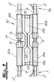
- a Parallelgurtvani 1 for in particular track construction and tunnel construction shown, with two parallel belt bars 2 and the belt bars 2 connecting transverse bars 3, for example diagonal bars.
- Anchoring slide 4 At least in the Codend Schemeen are Anchoring slide 4 arranged, each one Anchor plate 5 having double-sided pipe sections 6, wherein the anchor plates 5 each have at least one Opening 7 or perforation for passing a Rock anchor 8 have.
- the pipe sections 6 are on the belt bars 2 pushed and aligned in Carriage position fixable.
- the belt bars 2 are as Threaded rods formed.
- the anchoring carriages 4 are by means of one or both sides of the pipe sections. 6 arranged threaded nuts 9 fixable.
- a plurality of anchoring slide. 4 be arranged, which is not shown and only in Fig. 2 is indicated by the rock anchor 8.
- a Connection device 10 is provided, which after a first Embodiment two cranked and at least in the field their bent 11 welded together connecting rods 12 has.
- On the outsides of the connecting rods 12th are four pairs in their un-cranked areas fastened pipe sections 6 are provided, each of which two aligned pipe sections 6a, 6b on the one and on the other connecting rod 12 for insertion of Threaded nuts 9 by a predetermined amount from each other are distanced, wherein the one pipe pair 6a on the belt or threaded rods 2 of a parallel carrier.
- connection device 10 a connection tab 14 and on both sides the connecting tab 14 four paired attached Pipe sections 6a, 6b, of which two in each case aligned pipe sections 6a, 6b on one and the other Side of the connection tab 14 for insertion of Threaded nuts 9 by a predetermined amount from each other are distanced. Also in this case, that is one Pipe pair 6a on the belt bars 2 of the one Parallelgurtanys 1 and the other pair of pipe sections 6b on the belt bars 2 a to be connected Parallelgurtanys 1a pushed on.
- the pipe pair 6a, 6b and consequently the entire connection device 10 are by means of the belt bars 2 on one side or on both sides of the pipe sections 6 aufschraubbarer Threaded nuts 9 clamped in aligned position.
- the connecting tab 14 has an anchoring tab one or more openings 7.
- the parallel belt carrier 1 and the connection device 10 can be made of steel or plastic.
Landscapes
- Engineering & Computer Science (AREA)
- Mining & Mineral Resources (AREA)
- Architecture (AREA)
- Structural Engineering (AREA)
- General Life Sciences & Earth Sciences (AREA)
- Life Sciences & Earth Sciences (AREA)
- Civil Engineering (AREA)
- Geochemistry & Mineralogy (AREA)
- Geology (AREA)
- Devices Affording Protection Of Roads Or Walls For Sound Insulation (AREA)
- Lining And Supports For Tunnels (AREA)
- Bridges Or Land Bridges (AREA)
- Joining Of Building Structures In Genera (AREA)
- Mutual Connection Of Rods And Tubes (AREA)
Abstract
Description
- Fig. 1
- einen Parallelgurtträger in Draufsicht,
- Fig. 2
- den Gegenstand nach Fig. 1 als Kappe bei einem Türstock-Ausbau,
- Fig. 3
- einen vergrößerten Ausschnitt aus dem Gegenstand nach Fig. 1 im Bereich eines Verankerungsschlittens,
- Fig. 4
- den Gegenstand nach Fig. 3 in Ansicht aus Richtung des Pfeiles X,
- Fig. 5
- eine Anschlusseinrichtung für den Gegenstand nach Fig. 1 in Draufsicht,
- Fig. 6
- eine abgewandelte Ausführungsform des Gegenstandes nach Fig. 5 in Draufsicht und
- Fig. 7
- eine Montagefolge für den Gegenstand nach Fig. 6.
Claims (10)
- Parallelgurtträger (1) für insbesondere Streckenausbau und Tunnelausbau, mit zwei parallelen Gurtstangen (2) und die Gurtstangen (2) verbindenden Querstäben (3) und zumindest in den Trägerendbereichen angeordneten Verankerungsschlitten (4) mit jeweils einer Ankerplatte (5) mit beidseitigen Rohrabschnitten (6), wobei die Ankerplatten (5) jeweils zumindest eine Durchbrechung (7) zum Hindurchführen eines Gebirgsankers (8) aufweisen und die Rohrabschnitte (6) auf die Gurtstangen (2) aufgeschoben und in ausgerichteter Schlittenposition fixierbar sind.
- Parallelgurtträger nach Anspruch 1, dadurch gekennzeichnet, dass die Gurtstangen (2) als Gewindestangen ausgebildet und die Verankerungsschlitten (4) mittels einoder beidseitig der Rohrabschnitte (6) angeordneter Gewindemuttern (9) fixierbar sind.
- Parallelgurtträger nach Anspruch 1 oder 2, dadurch gekennzeichnet, dass über die Länge der Gurtstangen (2) mehrere Verankerungsschlitten (4) angeordnet sind.
- Parallelgurtträger nach einem der Ansprüche 1 bis 3, gekennzeichnet durch eine Anschlusseinrichtung (10) zur Verlängerung des Parallelgurtträgers (1), mit einer Verbindungslasche (14) und beidseitig an der Verbindungslasche (14) vier paarweise befestigten Rohrabschnitten (6), von denen jeweils zwei fluchtende Rohrabschnitte (6a, 6b) auf der einen und anderen Seite der Verbindungslasche (14) zum Einsetzen von Gewindemuttern (9) um ein vorgegebenes Maß voneinander distanziert sind, wobei das eine Rohrabschnittpaar (6a) auf die Gurtstangen (2) des einen Parallelgurtträgers (1) und das andere Rohrabschnittpaar (6b) auf die Gurtstangen (2) eines anzuschließenden Parallelgurtträgers (1a) aufschiebbar und mittels auf die Gurtstangen (2) einseitig oder beidseitig der Rohrabschnitte (6) aufschraubbarer Gewindemuttern (9) verspannbar sind.
- Parallelgurtträger nach einem der Ansprüche 1 bis 4, dadurch gekennzeichnet, dass die Verbindungslasche (14) unter Bildung einer Verankerungslasche eine oder mehrere Durchbrechungen (7) aufweist.
- Parallelgurtträger nach einem der Ansprüche 1 bis 3, gekennzeichnet durch eine Anschlusseinrichtung (10) zur Verlängerung des Parallelgurtträgers (1), mit zwei gekröpften und zumindest im Bereich ihrer Kröpfung (11) miteinander befestigten, zum Beispiel verschweißten Verbindungsstäben (12) und mit beidseitig an den Verbindungsstäben (12) in deren ungekröpften Bereichen vier paarweise befestigten Rohrabschnitten (6), von denen jeweils zwei fluchtende Rohrabschnitte (6a, 6b) an dem einen und dem anderen Verbindungsstab (12) zum Einsetzen von Gewindemuttern (9) um ein vorgegebenes Maß voneinander distanziert sind, wobei das eine Rohrabschnittpaar (6a) auf die Gurtstangen (2) des einen Parallelgurtträgers (1) und das andere Rohrabschnittpaar (6b) auf die Gurtstangen (2) eines anzuschließenden Parallelgurtträgers (1a) aufschiebbar und mittels auf die Gurtstangen (2) einseitig oder beidseitig der Rohrabschnitte (6) aufschraubbarer Gewindemuttern (9) verspannbar sind.
- Parallelgurtträger nach Anspruch 6, dadurch gekennzeichnet, dass die beiden Verbindungsstäbe (12) an ihren ungekröpften Stabenden mittels Stabilisierungsstegen (13) miteinander verbunden sind.
- Parallelgurtträger nach einem der Ansprüche 1 bis 3, dadurch gekennzeichnet, dass drei Parallelgurtträger (1) zu einem Dreigurtträger oder vier Parallelgurtträger (1) zu einem Viergurtträger zusammensetzbar sind.
- Parallelgurtträger nach einem der Ansprüche 1 bis 8, gekennzeichnet durch eine Ausführurigsform in Stahl oder Kunststoff.
- Parallelgurtträger nach einem der Ansprüche 1 bis 9, dadurch gekennzeichnet, dass die Anschlusseinrichtung (10) aus Stahl oder Kunststoff besteht.
Applications Claiming Priority (2)
| Application Number | Priority Date | Filing Date | Title |
|---|---|---|---|
| DE10336154 | 2003-08-07 | ||
| DE10336154A DE10336154B4 (de) | 2003-08-07 | 2003-08-07 | Parallelgurtträger, insbesondere für den Streckenausbau und Tunnelausbau |
Publications (3)
| Publication Number | Publication Date |
|---|---|
| EP1505253A2 true EP1505253A2 (de) | 2005-02-09 |
| EP1505253A3 EP1505253A3 (de) | 2005-04-20 |
| EP1505253B1 EP1505253B1 (de) | 2012-01-11 |
Family
ID=33547124
Family Applications (1)
| Application Number | Title | Priority Date | Filing Date |
|---|---|---|---|
| EP04011896A Expired - Lifetime EP1505253B1 (de) | 2003-08-07 | 2004-05-19 | Parallelgurtträger für insbesondere Streckenausbau und Tunnelausbau |
Country Status (8)
| Country | Link |
|---|---|
| US (1) | US6921232B2 (de) |
| EP (1) | EP1505253B1 (de) |
| AT (1) | ATE541111T1 (de) |
| AU (1) | AU2004203023B2 (de) |
| CA (1) | CA2473260C (de) |
| DE (1) | DE10336154B4 (de) |
| PL (1) | PL202381B1 (de) |
| ZA (1) | ZA200405125B (de) |
Cited By (4)
| Publication number | Priority date | Publication date | Assignee | Title |
|---|---|---|---|---|
| CN102182483A (zh) * | 2011-04-26 | 2011-09-14 | 山东大学 | 半刚性异型梁锚索桁架巷道支护系统 |
| WO2014091323A3 (en) * | 2012-12-14 | 2014-11-06 | Dream For Africa Trading And Projects (Proprietary) Limited | Wall support strap |
| WO2016097882A1 (en) * | 2014-12-19 | 2016-06-23 | Marius Page | Wall support strap |
| CN111576881A (zh) * | 2020-05-13 | 2020-08-25 | 武汉理工大学 | 开洞口叠合剪力墙内置对角钢筋桁架深连梁的施工方法 |
Families Citing this family (17)
| Publication number | Priority date | Publication date | Assignee | Title |
|---|---|---|---|---|
| US7510351B2 (en) * | 2006-03-28 | 2009-03-31 | Price Herbert S | Method for supporting a subsurface material |
| US7597505B2 (en) * | 2006-03-28 | 2009-10-06 | Price Herbert S | Roof bolt plate |
| US8224631B2 (en) * | 2008-08-18 | 2012-07-17 | Fci Holdings Delaware, Inc. | Stress, geologic, and support analysis methodology for underground openings |
| US20110036051A1 (en) * | 2009-08-14 | 2011-02-17 | Callahan Robert M | Reinforced girder |
| US20110036050A1 (en) * | 2009-08-14 | 2011-02-17 | Robert M Callahan | Reinforced girder |
| US20110036052A1 (en) * | 2009-08-14 | 2011-02-17 | Callahan Robert M | Reinforced girder |
| CN102518459B (zh) * | 2011-12-15 | 2014-04-30 | 湖南科技大学 | 一种深井煤巷用高强度可自动让压的锚索槽钢梁 |
| DE102012108471B3 (de) * | 2012-09-11 | 2013-09-26 | Bochumer Eisenhütte Heintzmann GmbH & Co. KG | Gitterträger |
| CN104653198B (zh) * | 2014-12-31 | 2017-02-01 | 中国科学院武汉岩土力学研究所 | 一种煤矿软岩大变形巷道支护中泡沫混凝土的充填施工方法 |
| US10151202B2 (en) * | 2015-02-13 | 2018-12-11 | Fci Holdings Delaware, Inc. | Rib strap |
| WO2018058021A1 (en) * | 2016-09-26 | 2018-03-29 | Fci Holdings Delaware, Inc. | Yieldable bearing block |
| WO2020171896A1 (en) * | 2019-02-20 | 2020-08-27 | Dsi Tunneling Llc | Underground support system and method |
| CN110513133B (zh) * | 2019-07-08 | 2020-10-09 | 华兆东南(运城)绿色建筑集成有限公司 | 一种具有滑动底座的装配式m型钢结构 |
| US11105199B2 (en) * | 2019-09-11 | 2021-08-31 | Square Cut Systems, LLC | System and method for supporting sidewalls or ribs in coal mines |
| US11242750B2 (en) | 2019-11-25 | 2022-02-08 | Fci Holdings Delaware, Inc. | Adjustable lattice girder |
| CN111022086B (zh) * | 2019-12-27 | 2021-10-22 | 周伟永 | 一种巷道工程支护用单层拱架及其快速支护方法 |
| WO2026053096A1 (en) * | 2024-09-04 | 2026-03-12 | Autostrade Per L'italia S.P.A. | Modular reinforcement panel for the construction of a wall |
Family Cites Families (12)
| Publication number | Priority date | Publication date | Assignee | Title |
|---|---|---|---|---|
| DE1198768B (de) * | 1960-08-29 | 1965-08-19 | Bernhard Langerbein Fa | Verbolzung fuer den druck- und zugfesten Anschluss von Grubenausbaurahmen |
| DE3066268D1 (en) * | 1979-06-25 | 1984-03-01 | Pantex Stahl Ag | Tubbing, use of this tubbing and method of constructing it |
| DE8125375U1 (de) * | 1981-09-01 | 1982-01-21 | Pantex-Stahl AG, 6233 Büron | Gittertraeger fuer den untertag-strecken- und schachtausbau |
| US4699547A (en) * | 1985-03-15 | 1987-10-13 | Seegmiller Ben L | Mine truss structures and method |
| US4666344A (en) * | 1985-12-16 | 1987-05-19 | Seegmiller Ben L | Truss systems and components thereof |
| DE8709411U1 (de) * | 1987-07-09 | 1987-08-27 | Pantex-Stahl AG, Büron | Ausbaubogen für den Tunnelbau |
| US4960348A (en) * | 1988-12-08 | 1990-10-02 | Seegmiller Ben L | Truss systems, components and methods for trussing arched mine roofs |
| US5018907A (en) * | 1988-12-13 | 1991-05-28 | Chugh Yoginder P | Mine roof system |
| US5193940A (en) * | 1991-08-23 | 1993-03-16 | Dyckerhoff & Widmann Ag | Mine roof support system |
| GB2287729B (en) * | 1994-07-07 | 1997-07-23 | Tunnel Ausbau Technik Gmbh | Connecting element and lattice girder interconnected with a plurality of said elements |
| US5755535A (en) * | 1996-08-19 | 1998-05-26 | Triad Support Systems, Inc. | Mine roof truss system and related installation method |
| DE20205133U1 (de) * | 2002-04-03 | 2002-07-25 | Bochumer Eisenhütte Heintzmann GmbH & Co. KG, 44793 Bochum | Gitterträger für die Bewehrung von Betonkonstruktionen |
-
2003
- 2003-08-07 DE DE10336154A patent/DE10336154B4/de not_active Expired - Fee Related
-
2004
- 2004-05-19 AT AT04011896T patent/ATE541111T1/de active
- 2004-05-19 EP EP04011896A patent/EP1505253B1/de not_active Expired - Lifetime
- 2004-06-28 ZA ZA200405125A patent/ZA200405125B/xx unknown
- 2004-07-05 AU AU2004203023A patent/AU2004203023B2/en not_active Ceased
- 2004-07-08 CA CA002473260A patent/CA2473260C/en not_active Expired - Fee Related
- 2004-07-12 PL PL369058A patent/PL202381B1/pl unknown
- 2004-07-20 US US10/895,244 patent/US6921232B2/en not_active Expired - Fee Related
Cited By (4)
| Publication number | Priority date | Publication date | Assignee | Title |
|---|---|---|---|---|
| CN102182483A (zh) * | 2011-04-26 | 2011-09-14 | 山东大学 | 半刚性异型梁锚索桁架巷道支护系统 |
| WO2014091323A3 (en) * | 2012-12-14 | 2014-11-06 | Dream For Africa Trading And Projects (Proprietary) Limited | Wall support strap |
| WO2016097882A1 (en) * | 2014-12-19 | 2016-06-23 | Marius Page | Wall support strap |
| CN111576881A (zh) * | 2020-05-13 | 2020-08-25 | 武汉理工大学 | 开洞口叠合剪力墙内置对角钢筋桁架深连梁的施工方法 |
Also Published As
| Publication number | Publication date |
|---|---|
| PL202381B1 (pl) | 2009-06-30 |
| US6921232B2 (en) | 2005-07-26 |
| AU2004203023A1 (en) | 2005-02-24 |
| EP1505253B1 (de) | 2012-01-11 |
| CA2473260C (en) | 2008-02-26 |
| EP1505253A3 (de) | 2005-04-20 |
| AU2004203023B2 (en) | 2009-07-23 |
| DE10336154B4 (de) | 2006-09-21 |
| ZA200405125B (en) | 2005-05-25 |
| US20050031420A1 (en) | 2005-02-10 |
| PL369058A1 (en) | 2005-02-21 |
| CA2473260A1 (en) | 2005-02-07 |
| ATE541111T1 (de) | 2012-01-15 |
| DE10336154A1 (de) | 2005-03-03 |
Similar Documents
| Publication | Publication Date | Title |
|---|---|---|
| EP1505253B1 (de) | Parallelgurtträger für insbesondere Streckenausbau und Tunnelausbau | |
| DE60319282T2 (de) | Verfahren zur verankerung von paralleldrahtkabeln | |
| DE1608289B1 (de) | Ankerausbau fuer die Firste von Abbaustrecken in Bergwerken | |
| DE2717869B2 (de) | Verfahren zum Aussteifen eines dünnwandigen Hüllrohrs und zum Einfädeln eines Spannglieds in das Hüllrohr | |
| WO2013091893A1 (de) | Schutzverbauung | |
| WO2016202545A1 (de) | Gitterstruktur sowie vorrichtung bzw. verfahren zu deren herstellung | |
| DE2910239C2 (de) | Vorrichtung zum Schutz gegen Steinschlag und Lawinen in gebirgigem Gelände | |
| DE3012613C2 (de) | Ankerausbau für Strecken des untertägigen Bergbaus, Tunnel o.dgl. | |
| DE102009012085A1 (de) | Ankermatte für den untertägigen Berg- und Tunnelbau | |
| DE2854579A1 (de) | Bewehrungsrollmatte | |
| EP3907330B1 (de) | Steinschlagverbauung | |
| EP3309299B1 (de) | Schutzverbauung | |
| DE2949963C2 (de) | Verfahren zum Ausbessern und Verstärken von Streckenausbau und dafür geeignete Verzugmatte | |
| CH711370A2 (de) | Schutznetz, vorzugsweise zum Auskleiden von Tunnelwänden im Minenbau oder für die Sicherung von Erdoberflächenschichten. | |
| AT65502B (de) | Kriegsbrücke. | |
| DE2329943A1 (de) | Gittertraeger | |
| DD289081A5 (de) | Bogenfoermiges oder abgewinkeltes tragwerk | |
| DE29614929U1 (de) | Fahrspurtrenneinrichtung | |
| DE10101965C1 (de) | Anordnung zum Verbinden von zwei nebeneinander angeordneten Schalelementen einer Trägerschalung für Bauwerke aus Beton | |
| DE2517652A1 (de) | Streckenausbau fuer den berg- und tunnelbau | |
| DE2732363C2 (de) | Verzugblech | |
| DE3426991C2 (de) | ||
| DE1608289C2 (de) | Ankerausbau für die Firste von Abbaustrecken In Bergwerken | |
| DE1926863A1 (de) | Ausbau fuer Tunnel- oder Grubenstrecken | |
| AT516514B1 (de) | Vorrichtung zur Hangabstützung |
Legal Events
| Date | Code | Title | Description |
|---|---|---|---|
| PUAI | Public reference made under article 153(3) epc to a published international application that has entered the european phase |
Free format text: ORIGINAL CODE: 0009012 |
|
| AK | Designated contracting states |
Kind code of ref document: A2 Designated state(s): AT BE BG CH CY CZ DE DK EE ES FI FR GB GR HU IE IT LI LU MC NL PL PT RO SE SI SK TR |
|
| AX | Request for extension of the european patent |
Extension state: AL HR LT LV MK |
|
| PUAL | Search report despatched |
Free format text: ORIGINAL CODE: 0009013 |
|
| AK | Designated contracting states |
Kind code of ref document: A3 Designated state(s): AT BE BG CH CY CZ DE DK EE ES FI FR GB GR HU IE IT LI LU MC NL PL PT RO SE SI SK TR |
|
| AX | Request for extension of the european patent |
Extension state: AL HR LT LV MK |
|
| 17P | Request for examination filed |
Effective date: 20050727 |
|
| AKX | Designation fees paid |
Designated state(s): AT CH DE GB LI |
|
| GRAP | Despatch of communication of intention to grant a patent |
Free format text: ORIGINAL CODE: EPIDOSNIGR1 |
|
| RIN1 | Information on inventor provided before grant (corrected) |
Inventor name: PODJADTKE, RUDI DIPL.-ING. Inventor name: WUNDERLICH, FRANZ-JOSEF DIPL.-ING. Inventor name: DOMANSKI, LOTHAR DIPL.-ING. |
|
| GRAS | Grant fee paid |
Free format text: ORIGINAL CODE: EPIDOSNIGR3 |
|
| GRAA | (expected) grant |
Free format text: ORIGINAL CODE: 0009210 |
|
| AK | Designated contracting states |
Kind code of ref document: B1 Designated state(s): AT CH DE GB LI |
|
| REG | Reference to a national code |
Ref country code: GB Ref legal event code: FG4D Free format text: NOT ENGLISH |
|
| REG | Reference to a national code |
Ref country code: CH Ref legal event code: EP |
|
| REG | Reference to a national code |
Ref country code: AT Ref legal event code: REF Ref document number: 541111 Country of ref document: AT Kind code of ref document: T Effective date: 20120115 |
|
| REG | Reference to a national code |
Ref country code: DE Ref legal event code: R096 Ref document number: 502004013210 Country of ref document: DE Effective date: 20120308 |
|
| REG | Reference to a national code |
Ref country code: CH Ref legal event code: NV Representative=s name: PATENTANWAELTE SCHAAD, BALASS, MENZL & PARTNER AG |
|
| PLBE | No opposition filed within time limit |
Free format text: ORIGINAL CODE: 0009261 |
|
| STAA | Information on the status of an ep patent application or granted ep patent |
Free format text: STATUS: NO OPPOSITION FILED WITHIN TIME LIMIT |
|
| 26N | No opposition filed |
Effective date: 20121012 |
|
| REG | Reference to a national code |
Ref country code: DE Ref legal event code: R097 Ref document number: 502004013210 Country of ref document: DE Effective date: 20121012 |
|
| PGFP | Annual fee paid to national office [announced via postgrant information from national office to epo] |
Ref country code: CH Payment date: 20150521 Year of fee payment: 12 Ref country code: GB Payment date: 20150521 Year of fee payment: 12 |
|
| PGFP | Annual fee paid to national office [announced via postgrant information from national office to epo] |
Ref country code: AT Payment date: 20150521 Year of fee payment: 12 |
|
| PGFP | Annual fee paid to national office [announced via postgrant information from national office to epo] |
Ref country code: DE Payment date: 20160519 Year of fee payment: 13 |
|
| REG | Reference to a national code |
Ref country code: CH Ref legal event code: PL |
|
| REG | Reference to a national code |
Ref country code: AT Ref legal event code: MM01 Ref document number: 541111 Country of ref document: AT Kind code of ref document: T Effective date: 20160519 |
|
| GBPC | Gb: european patent ceased through non-payment of renewal fee |
Effective date: 20160519 |
|
| PG25 | Lapsed in a contracting state [announced via postgrant information from national office to epo] |
Ref country code: LI Free format text: LAPSE BECAUSE OF NON-PAYMENT OF DUE FEES Effective date: 20160531 Ref country code: CH Free format text: LAPSE BECAUSE OF NON-PAYMENT OF DUE FEES Effective date: 20160531 |
|
| PG25 | Lapsed in a contracting state [announced via postgrant information from national office to epo] |
Ref country code: AT Free format text: LAPSE BECAUSE OF NON-PAYMENT OF DUE FEES Effective date: 20160519 |
|
| PG25 | Lapsed in a contracting state [announced via postgrant information from national office to epo] |
Ref country code: GB Free format text: LAPSE BECAUSE OF NON-PAYMENT OF DUE FEES Effective date: 20160519 |
|
| REG | Reference to a national code |
Ref country code: DE Ref legal event code: R119 Ref document number: 502004013210 Country of ref document: DE |
|
| PG25 | Lapsed in a contracting state [announced via postgrant information from national office to epo] |
Ref country code: DE Free format text: LAPSE BECAUSE OF NON-PAYMENT OF DUE FEES Effective date: 20171201 |