EP1505254A2 - Turbine à gaz et méthode pour la refroidir - Google Patents
Turbine à gaz et méthode pour la refroidir Download PDFInfo
- Publication number
- EP1505254A2 EP1505254A2 EP04103627A EP04103627A EP1505254A2 EP 1505254 A2 EP1505254 A2 EP 1505254A2 EP 04103627 A EP04103627 A EP 04103627A EP 04103627 A EP04103627 A EP 04103627A EP 1505254 A2 EP1505254 A2 EP 1505254A2
- Authority
- EP
- European Patent Office
- Prior art keywords
- gas turbine
- steam
- cooling
- air
- cooling device
- Prior art date
- Legal status (The legal status is an assumption and is not a legal conclusion. Google has not performed a legal analysis and makes no representation as to the accuracy of the status listed.)
- Granted
Links
Images

Classifications
-
- F—MECHANICAL ENGINEERING; LIGHTING; HEATING; WEAPONS; BLASTING
- F01—MACHINES OR ENGINES IN GENERAL; ENGINE PLANTS IN GENERAL; STEAM ENGINES
- F01D—NON-POSITIVE DISPLACEMENT MACHINES OR ENGINES, e.g. STEAM TURBINES
- F01D5/00—Blades; Blade-carrying members; Heating, heat-insulating, cooling or antivibration means on the blades or the members
- F01D5/12—Blades
- F01D5/14—Form or construction
- F01D5/18—Hollow blades, i.e. blades with cooling or heating channels or cavities; Heating, heat-insulating or cooling means on blades
- F01D5/186—Film cooling
-
- F—MECHANICAL ENGINEERING; LIGHTING; HEATING; WEAPONS; BLASTING
- F05—INDEXING SCHEMES RELATING TO ENGINES OR PUMPS IN VARIOUS SUBCLASSES OF CLASSES F01-F04
- F05D—INDEXING SCHEME FOR ASPECTS RELATING TO NON-POSITIVE-DISPLACEMENT MACHINES OR ENGINES, GAS-TURBINES OR JET-PROPULSION PLANTS
- F05D2260/00—Function
- F05D2260/20—Heat transfer, e.g. cooling
- F05D2260/232—Heat transfer, e.g. cooling characterized by the cooling medium
- F05D2260/2322—Heat transfer, e.g. cooling characterized by the cooling medium steam
Definitions
- the present invention relates to a gas turbine, in particular in one Power plant.
- the invention also relates to an associated method for cooling the gas turbine.
- Steam is due to its higher heat capacity and its lower viscosity, in principle, a better cooling medium than air. Steam In addition to cooling air also reduces the specific compressor power through the elimination of the pressure losses of the cooling air and reduces the NOX emissions by a lower at the same turbine inlet temperature Combustion chamber temperature.
- the steam cooling can be designed as an open or closed system become.
- an open system eg film cooling of the blades
- the Steam after he has fulfilled his cooling task, added to the working gas and thus acts as an efficiency and efficiency enhancer on the gas turbine.
- the present invention as characterized in the claims deals with the problem, for a gas turbine initially mentioned kind to provide an improved embodiment, with which in particular a Higher performance and extended life of critical components can be achieved.
- the invention is based on the general idea, in a gas turbine, which with a conventional air cooling device for cooling parts of Gas turbine is formed by means of air, in addition a steam cooling device provide, which for cooling parts of the gas turbine by means of steam is trained.
- the cooling of a rotor and a stator of the gas turbine Conventionally carried out with air, while additionally a small amount of steam e.g. from entering the turbine to exiting the turbine along a Rotor shell flows parallel to the hot gas flow. Steam is due to his higher heat capacity and its lower viscosity in principle a better Cooling medium as air. Steam instead of cooling air also reduces the required Coolant volume by approx. 50%.
- the essential advantage of the invention is that the performance of the additionally with steam cooled gas turbine compared to the conventional one air-cooled gas turbine increases by about 2 to 5%. This results from the higher turbine inlet temperature, which leads to a higher power. It is also noteworthy that only a comparatively small, purposeful applied amount of steam is needed, in conjunction with the air cooling a to achieve intensive cooling of the gas turbine.
- the steam cooling device may be designed at least for cooling the inner inner lining and / or the inner outer lining of the combustion chamber and / or the guide vanes and / or hub-side covering elements of the vanes, and / or for a steam guide to do so is formed, that from the row of vanes along a rotor shell, a vapor film is formed.
- This steam film protects the rotor from contact with the hot gas flow and thus leads to an extended life of the critical components of the gas turbine.
- the Steam cooling device for cooling an upstream region of the Guide vanes and the air cooling device for cooling a downstream side Be formed portion of the vanes offers the advantage that the Guide vanes in the thermally more heavily loaded inflow area intensively with steam be cooled.
- the invention uses the knowledge that for cooling the thermally less heavily polluted outflow area the air cooling sufficient, whereby with comparatively little energy a sufficient Blade cooling is achieved. If the injected for cooling steam over Outlets again exits into the hot gas stream, he produced at the Outer skin of the respective vane a fine vapor layer, which over the guide vanes and this similar to the rotor shell described above Protects against direct contact with the hot gas stream and thus to Robustness of the gas turbine contributes.
- the steam required for the steam cooling device can advantageously from a Waste heat boiler are taken from a steam turbine, which with the Gas turbine is coupled.
- the steam cooling thus requires no additional Steam generator.
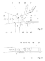
- a gas turbine 1 according to the invention comprises a combustion chamber 2 (burner not shown), a stator 5, a rotor 8 and a partially shown air cooling device 31 and also only partially shown steam cooling device 32nd
- the combustion chamber 2 is of a surrounded inner lining 3 and an inner outer lining 4.
- a hot gas stream 28 heated in the combustion chamber 2 strikes at least one row of guide vanes 6 with a plurality of guide vanes 7, which each have an inflow-side region 14 and an outflow-side region 15.
- a blade row 9 with a plurality of blades 10, which form part of the rotor 8.
- the steam cooling device 32 comprises a first cooling channel 24, which is arranged in the inner outer lining and, during operation of the steam cooling device 32, flows through vapor D.
- the first cooling channel 24 communicates at the end via an outer cover plate 29 with a third cooling channel 25, which is integrated in the guide blade 7.
- the third cooling channel 25 is arranged in the inflow-side region 14 of the guide vane 7 and has outlet openings 27, which communicate with the hot gas stream 28 on an outer side of the respective vane 7.
- the third cooling channel 27 communicates at the end with hub-side cover elements 11, so that the remaining, not exited through the outlet openings 27 steam D flows into the hub-side cover 11 and this also cools.
- outlet openings 27 ' are provided on the hub-side covering elements 11, from which the vapor D exits into the gas turbine 1 in the region of an inlet 21.
- the goal here is that most of the vapor D exits through the outlet openings 27 '.
- a second cooling channel 23 which is substantially parallel to the hot gas stream 28 in Direction of the vanes 7 runs.
- the second cooling channel 23 communicates at the end via outlet openings 27 ", which in the region of the hub side Covering elements 11 are arranged, with the hot gas stream 28 at the entrance of the Gas turbine 1.
- the steam D required for the steam cooling device 32 can advantageously not shown steam generators, in particular from a waste heat boiler, a Startup steam generator or a steam turbine can be removed, which with the gas turbine is coupled. An additional steam generator for the Steam cooling is therefore not required.
- the air cooling device 31 comprises a fourth cooling channel 26 of FIG is integrated into the guide vanes 7 in the downstream region 15.
- the cooling channel 26 is the input side with a cooling air source, not shown, beispw.
- the fourth Cooling channel 26 is traversed by air L and cooled by this.
- the blade row 9 Downstream of the guide vane row 6 is the blade row 9 with several Blades 10 arranged.
- the blades 10 are as in conventional Gas turbine 1 cooled with air L, which in the illustrated embodiment the rotor side flows into the blades 10.
- the air cooling device 31 is both according to the illustrated embodiment for cooling the blades 10 as well as downstream of the vanes. 7 arranged heat accumulation elements 19 is formed. The cooling of the Heat storage elements 19 takes place by cooling the hot gas stream 28 facing away from the heat accumulation elements 19. Additionally or alternatively can according to FIG. 1 air L immediately downstream of the blades 10 in the Gas turbine 1 are blown and thus cooling the furnishedstauicide 19 on the hot gas stream 28 side facing or cause and / or reinforce the rotor shell 12.
- the usual cooling medium of hot gas components in a gas turbine 1 is air L, which from an end or intermediate stage of a not shown Compressor is removed.
- Critical places are the inside Interior trim 3 and the inside 4 of the outer lining Combustion chamber 2, the first row of vanes 6, the first blade row. 9 and the turbine rotor 8.
- the invention proposes a combined cooling by means of steam D and Air L ahead.
- the preferably slightly superheated steam D of the steam cooling device 32 flows in designated cooling channels 23 of the inner lining 3 (Inner liner) and cooling channels 24 of the inner outer lining 4 (Outer liner) from the burner side.
- the inflowing steam D emerges from the end of the first cooling channel 24 and then is a Leitschaufelau jointplatte 29 in a followed by the third cooling channel 25 forwarded.
- the steam D flows into the hub-side cover plate 11 of the guide vane 7 and via outlet openings 27 'in the gas turbine 1.
- the steam D flows via outlet openings 27 in the upstream region 14 of the guide vanes 7 in The gas turbine 1.
- the goal here is that the majority of the steam D at the Hub exits.
- Another vapor stream D is fed to the inner liner 3 on the burner side and flows through cooling channels 23 of the inner liner 3 parallel to the hot gas stream 28th to the outlet opening 27 "in the region of the hub-side cover 11th
- the two vapor streams D of the inner liner 3 and the hub side Cover plate 11 form due to the higher density of the vapor D opposite the hot gas stream 28 during the expansion along the turbine 1 downstream of the Guide vanes 7 a steam curtain or film 13 of a certain current thickness along the rotor shell 12 or at the edge of the hot gas flow 28.
- This Steam film 13 protects the rotor 8 from contact with the hot gas stream 28 and leads thereby to an extended life of the critical components of Gas turbine 1.
- the inner lining 3 and the inner outer lining 4 are cooled with steam D.
- the steam required for this is approx. 50% of the amount of cooling air.
- the slightly overheated steam D required for cooling is preferably removed from a waste heat boiler, not shown. there can be provided that both the first cooling channel 24 and the second Cooling channel 23 from a common or separate waste heat boiler (s) can be fed.
- the power of the operated with the combined air or steam cooling Gas turbine 1 takes over the conventional air-cooled gas turbine about 2 to 5 percent, resulting in a combined gas turbine steam turbine plant
- the steam turbine power decreases due to the removal of the slightly superheated steam D from the waste heat boiler slightly, whereas the heat output of the waste heat boiler as a result of larger amount of gas turbine increases. Almost the largest part of this Performance is therefore due to the relaxation of the steam after cooling the inner lining 3,4 and the guide vanes 7 at a much higher Temperature and recovered at up to 1 bar in the gas turbine 1.
- the Saved cooling air amount of the guide vanes 7 flows through the combustion chamber. 2 and takes part in the combustion process, whereby an additional power of the Gas turbine 1 is achieved.
- the gas turbine 1 is shown in another embodiment, which is designed to carry out a sequential combustion.
- a high-pressure combustion chamber 2 'and a Hochdruckleitschaufelsch 22 are provided with a plurality of Hochdruckleitschaufeln 16 and at least one high-pressure blade row 17 with a plurality of high-pressure blades 18, which are followed downstream of a low-pressure combustion chamber and a low-pressure turbine, not shown.
- the high pressure blades 18 and the high pressure vanes 16 are cooled at least in their Anström Jardin with steam D, while the trailing edges of the high pressure vanes 16 can be cooled either also with steam or conventional with air.
- the design of the various cooling channels is designed so that a certain amount of steam flows through the high-pressure guide vanes 16 into the hub-side cover elements 11.
- a large part of the steam D then flows into the gas turbine 1 via outlet openings 27 'in a manner similar to that in FIG.
- the other part of the steam D flows into a gap 30, which is arranged below the rotor shell 12 and between the high pressure vanes 16 and the high pressure blades 18 to be sucked from there by the high pressure blades 18 for cooling.
- a portion of the steam D blocks the described gap 30 between Hochdruckleit- and high-pressure blades 16,18 with a certain amount of blown steam D.
- the remaining components are air-cooled.
- gas turbine 1 with sequential combustion produces the exited through the outlet openings 27 'vapor D a Steam film 13, which surrounds the rotor shell 12 and this before direct Contact with the hot gas stream 28 protects.
- Fig. 3 is a variant for cooling a High pressure compressor 20 shown.
- the invention provides, in a gas turbine 1, which with a conventional Air cooling device 31 for cooling parts of the gas turbine 1 by means of air is formed, in addition to provide a steam cooling device 32, which for Cooling of parts of the gas turbine 1 is formed by means of steam.
- the cooling of the rotor 8 and the stator 5 is conventional with air L executed.
- the advantages of the invention are that the performance of the additional with Steam D cooled gas turbine 1 compared to the conventional air-cooled Gas turbine 1, e.g. by about 2 to 5%, increases and at the same time due to the Steam films 13 a longer life of the critical components can be achieved can.
Landscapes
- Engineering & Computer Science (AREA)
- Mechanical Engineering (AREA)
- General Engineering & Computer Science (AREA)
- Turbine Rotor Nozzle Sealing (AREA)
Applications Claiming Priority (2)
| Application Number | Priority Date | Filing Date | Title |
|---|---|---|---|
| DE10336432A DE10336432A1 (de) | 2003-08-08 | 2003-08-08 | Gasturbine und zugehöriges Kühlverfahren |
| DE10336432 | 2003-08-08 |
Publications (3)
| Publication Number | Publication Date |
|---|---|
| EP1505254A2 true EP1505254A2 (fr) | 2005-02-09 |
| EP1505254A3 EP1505254A3 (fr) | 2012-07-04 |
| EP1505254B1 EP1505254B1 (fr) | 2017-01-25 |
Family
ID=33547152
Family Applications (1)
| Application Number | Title | Priority Date | Filing Date |
|---|---|---|---|
| EP04103627.8A Expired - Lifetime EP1505254B1 (fr) | 2003-08-08 | 2004-07-28 | Turbine à gaz et méthode pour la refroidir |
Country Status (4)
| Country | Link |
|---|---|
| US (1) | US7040097B2 (fr) |
| EP (1) | EP1505254B1 (fr) |
| CN (1) | CN100507237C (fr) |
| DE (1) | DE10336432A1 (fr) |
Cited By (4)
| Publication number | Priority date | Publication date | Assignee | Title |
|---|---|---|---|---|
| EP1921270A3 (fr) * | 2006-11-10 | 2010-11-03 | General Electric Company | Moteur combiné avec des aubes fixes refroidies |
| US7870742B2 (en) | 2006-11-10 | 2011-01-18 | General Electric Company | Interstage cooled turbine engine |
| US7926289B2 (en) | 2006-11-10 | 2011-04-19 | General Electric Company | Dual interstage cooled engine |
| US8783044B2 (en) | 2007-12-29 | 2014-07-22 | Alstom Technology Ltd | Turbine stator nozzle cooling structure |
Families Citing this family (22)
| Publication number | Priority date | Publication date | Assignee | Title |
|---|---|---|---|---|
| DE102005060704A1 (de) * | 2005-12-19 | 2007-06-28 | Rolls-Royce Deutschland Ltd & Co Kg | Gasturbinenbrennkammer |
| US7967568B2 (en) * | 2007-09-21 | 2011-06-28 | Siemens Energy, Inc. | Gas turbine component with reduced cooling air requirement |
| US8079804B2 (en) * | 2008-09-18 | 2011-12-20 | Siemens Energy, Inc. | Cooling structure for outer surface of a gas turbine case |
| CN101798959A (zh) * | 2010-02-10 | 2010-08-11 | 马鞍山科达洁能有限公司 | 燃气轮机 |
| DE102010009477A1 (de) * | 2010-02-26 | 2011-09-01 | Rolls-Royce Deutschland Ltd & Co Kg | Fluggasturbinenantrieb |
| CH703105A1 (de) * | 2010-05-05 | 2011-11-15 | Alstom Technology Ltd | Gasturbine mit einer sekundärbrennkammer. |
| RU2543101C2 (ru) | 2010-11-29 | 2015-02-27 | Альстом Текнолоджи Лтд | Осевая газовая турбина |
| US20120186261A1 (en) * | 2011-01-20 | 2012-07-26 | General Electric Company | System and method for a gas turbine exhaust diffuser |
| CN102278813A (zh) * | 2011-09-13 | 2011-12-14 | 牟敦善 | 串联式电加热器热水箱温水箱 |
| US10094285B2 (en) | 2011-12-08 | 2018-10-09 | Siemens Aktiengesellschaft | Gas turbine outer case active ambient cooling including air exhaust into sub-ambient cavity |
| US8894359B2 (en) | 2011-12-08 | 2014-11-25 | Siemens Aktiengesellschaft | Gas turbine engine with outer case ambient external cooling system |
| AU2013219140B2 (en) | 2012-08-24 | 2015-10-08 | Ansaldo Energia Switzerland AG | Method for mixing a dilution air in a sequential combustion system of a gas turbine |
| US10094570B2 (en) | 2014-12-11 | 2018-10-09 | General Electric Company | Injector apparatus and reheat combustor |
| US10094569B2 (en) | 2014-12-11 | 2018-10-09 | General Electric Company | Injecting apparatus with reheat combustor and turbomachine |
| US10107498B2 (en) | 2014-12-11 | 2018-10-23 | General Electric Company | Injection systems for fuel and gas |
| US10094571B2 (en) | 2014-12-11 | 2018-10-09 | General Electric Company | Injector apparatus with reheat combustor and turbomachine |
| US10883387B2 (en) * | 2016-03-07 | 2021-01-05 | General Electric Company | Gas turbine exhaust diffuser with air injection |
| US10669887B2 (en) * | 2018-02-15 | 2020-06-02 | Raytheon Technologies Corporation | Vane airfoil cooling air communication |
| US11686210B2 (en) | 2021-03-24 | 2023-06-27 | General Electric Company | Component assembly for variable airfoil systems |
| US11920526B1 (en) * | 2022-08-12 | 2024-03-05 | Rtx Corporation | Inter-cooled preheat of steam injected turbine engine |
| US12392287B2 (en) | 2023-03-14 | 2025-08-19 | Rtx Corporation | Steam cooling turbine stator vane array |
| US12359587B2 (en) | 2023-09-12 | 2025-07-15 | Rolls-Royce North American Technologies, Inc. | Gas turbine engine power cable cooling |
Citations (2)
| Publication number | Priority date | Publication date | Assignee | Title |
|---|---|---|---|---|
| EP0911489A1 (fr) | 1997-05-01 | 1999-04-28 | Mitsubishi Heavy Industries, Ltd. | Pale stationnaire servant au refroidissement d'une turbine a gaz |
| EP0955449A1 (fr) | 1998-03-12 | 1999-11-10 | Mitsubishi Heavy Industries, Ltd. | Aube pour turbine à gaz |
Family Cites Families (8)
| Publication number | Priority date | Publication date | Assignee | Title |
|---|---|---|---|---|
| US4314442A (en) * | 1978-10-26 | 1982-02-09 | Rice Ivan G | Steam-cooled blading with steam thermal barrier for reheat gas turbine combined with steam turbine |
| US4571935A (en) * | 1978-10-26 | 1986-02-25 | Rice Ivan G | Process for steam cooling a power turbine |
| DE3003347A1 (de) * | 1979-12-20 | 1981-06-25 | BBC AG Brown, Boveri & Cie., Baden, Aargau | Gekuehlte wand |
| US4413477A (en) * | 1980-12-29 | 1983-11-08 | General Electric Company | Liner assembly for gas turbine combustor |
| US4565490A (en) * | 1981-06-17 | 1986-01-21 | Rice Ivan G | Integrated gas/steam nozzle |
| JP3142850B2 (ja) * | 1989-03-13 | 2001-03-07 | 株式会社東芝 | タービンの冷却翼および複合発電プラント |
| US5253976A (en) * | 1991-11-19 | 1993-10-19 | General Electric Company | Integrated steam and air cooling for combined cycle gas turbines |
| US5340274A (en) * | 1991-11-19 | 1994-08-23 | General Electric Company | Integrated steam/air cooling system for gas turbines |
-
2003
- 2003-08-08 DE DE10336432A patent/DE10336432A1/de not_active Withdrawn
-
2004
- 2004-07-28 EP EP04103627.8A patent/EP1505254B1/fr not_active Expired - Lifetime
- 2004-08-06 US US10/912,119 patent/US7040097B2/en not_active Expired - Lifetime
- 2004-08-09 CN CNB2004100565554A patent/CN100507237C/zh not_active Expired - Fee Related
Patent Citations (2)
| Publication number | Priority date | Publication date | Assignee | Title |
|---|---|---|---|---|
| EP0911489A1 (fr) | 1997-05-01 | 1999-04-28 | Mitsubishi Heavy Industries, Ltd. | Pale stationnaire servant au refroidissement d'une turbine a gaz |
| EP0955449A1 (fr) | 1998-03-12 | 1999-11-10 | Mitsubishi Heavy Industries, Ltd. | Aube pour turbine à gaz |
Cited By (5)
| Publication number | Priority date | Publication date | Assignee | Title |
|---|---|---|---|---|
| EP1921270A3 (fr) * | 2006-11-10 | 2010-11-03 | General Electric Company | Moteur combiné avec des aubes fixes refroidies |
| US7870742B2 (en) | 2006-11-10 | 2011-01-18 | General Electric Company | Interstage cooled turbine engine |
| US7870743B2 (en) | 2006-11-10 | 2011-01-18 | General Electric Company | Compound nozzle cooled engine |
| US7926289B2 (en) | 2006-11-10 | 2011-04-19 | General Electric Company | Dual interstage cooled engine |
| US8783044B2 (en) | 2007-12-29 | 2014-07-22 | Alstom Technology Ltd | Turbine stator nozzle cooling structure |
Also Published As
| Publication number | Publication date |
|---|---|
| CN1580520A (zh) | 2005-02-16 |
| CN100507237C (zh) | 2009-07-01 |
| EP1505254B1 (fr) | 2017-01-25 |
| US7040097B2 (en) | 2006-05-09 |
| EP1505254A3 (fr) | 2012-07-04 |
| DE10336432A1 (de) | 2005-03-10 |
| US20050172634A1 (en) | 2005-08-11 |
Similar Documents
| Publication | Publication Date | Title |
|---|---|---|
| EP1505254B1 (fr) | Turbine à gaz et méthode pour la refroidir | |
| DE2320581C2 (de) | Gasturbine mit luftgekühlten Turbinenlaufschaufeln | |
| DE102009044585B4 (de) | Verfahren zum Betreiben eines Turbinentriebwerks und Anordnung in einem Turbinentriebwerk | |
| DE69403444T2 (de) | Turbinenleitschaufel mit einer gekühlten abdeckung | |
| EP1386070B1 (fr) | Procede de refroidissement d'une turbine a gaz, et installation de turbine a gaz | |
| DE2913548C2 (de) | Wellenkühlung für ein Gasturbinentriebwerk | |
| DE60118848T2 (de) | Tandemkühlung für eine Turbinenschaufel | |
| DE60029560T2 (de) | Turbinenleitschaufel-Segment mit inneren Kühlkreisläufen | |
| DE602004000527T2 (de) | Verfahren zur Kühlung von heissen Turbinenbauteilen mittels eines teilweise in einem externen Wärmetauscher gekühlten Luftstromes und so gekühltes Turbinentriebwerk | |
| DE60132405T2 (de) | Kühlung von Turbinenschaufeln durch spezifische Schaufelverteilung | |
| DE69503628T3 (de) | Leitschaufelkühlung mit doppelquelle | |
| EP3059433B1 (fr) | Turbine a gaz avec refroidisseur d'huile dans l'habillage de la turbine | |
| EP1162355B1 (fr) | Méthode de refroidissement d'une turbine à gaz et turbine à gaz correspondante | |
| EP1656497B1 (fr) | Diffuseur situe entre le compresseur et la chambre de combustion d'une turbine a gaz | |
| DE602005000350T2 (de) | Turbinenstatorschaufel mit verbesserter Kühlung | |
| EP2179143B1 (fr) | Refroidissement de fente entre une paroi de chambre de combustion et une paroi de turbine d'une installation de turbine à gaz | |
| DE102010037862A1 (de) | Wirbelkammern zur Spaltströmungssteuerung | |
| DE60319486T2 (de) | Gekühlte Leitschaufeln in einer Gasturbine | |
| EP2084368A1 (fr) | Aube de turbine | |
| EP1245806A1 (fr) | Aube de turbine refroidie | |
| WO1998013584A1 (fr) | Compensation de la perte de pression d'une conduite d'air de refroidissement dans une installation de turbine a gaz | |
| DE10392802B4 (de) | Dampfturbine | |
| EP1165942A1 (fr) | Turbomachine avec un systeme d'elements de paroi pouvant etre refroidi et procede de refroidissement d'un systeme d'elements de paroi | |
| EP1644614A1 (fr) | Aube refroidie pour une turbine a gaz | |
| EP1716316A1 (fr) | Turbine a gaz a carter de compresseur protege du refroidissement et procede pour faire fonctionner une turbine a gaz |
Legal Events
| Date | Code | Title | Description |
|---|---|---|---|
| PUAI | Public reference made under article 153(3) epc to a published international application that has entered the european phase |
Free format text: ORIGINAL CODE: 0009012 |
|
| AK | Designated contracting states |
Kind code of ref document: A2 Designated state(s): AT BE BG CH CY CZ DE DK EE ES FI FR GB GR HU IE IT LI LU MC NL PL PT RO SE SI SK TR |
|
| AX | Request for extension of the european patent |
Extension state: AL HR LT LV MK |
|
| PUAL | Search report despatched |
Free format text: ORIGINAL CODE: 0009013 |
|
| AK | Designated contracting states |
Kind code of ref document: A3 Designated state(s): AT BE BG CH CY CZ DE DK EE ES FI FR GB GR HU IE IT LI LU MC NL PL PT RO SE SI SK TR |
|
| AX | Request for extension of the european patent |
Extension state: AL HR LT LV MK |
|
| RIC1 | Information provided on ipc code assigned before grant |
Ipc: F01D 5/18 20060101AFI20120530BHEP |
|
| 17P | Request for examination filed |
Effective date: 20121210 |
|
| 17Q | First examination report despatched |
Effective date: 20130121 |
|
| AKX | Designation fees paid |
Designated state(s): AT BE BG CH CY CZ DE DK EE ES FI FR GB GR HU IE IT LI LU MC NL PL PT RO SE SI SK TR |
|
| RAP1 | Party data changed (applicant data changed or rights of an application transferred) |
Owner name: GENERAL ELECTRIC TECHNOLOGY GMBH |
|
| GRAP | Despatch of communication of intention to grant a patent |
Free format text: ORIGINAL CODE: EPIDOSNIGR1 |
|
| INTG | Intention to grant announced |
Effective date: 20160902 |
|
| GRAS | Grant fee paid |
Free format text: ORIGINAL CODE: EPIDOSNIGR3 |
|
| GRAA | (expected) grant |
Free format text: ORIGINAL CODE: 0009210 |
|
| STAA | Information on the status of an ep patent application or granted ep patent |
Free format text: STATUS: THE PATENT HAS BEEN GRANTED |
|
| AK | Designated contracting states |
Kind code of ref document: B1 Designated state(s): AT BE BG CH CY CZ DE DK EE ES FI FR GB GR HU IE IT LI LU MC NL PL PT RO SE SI SK TR |
|
| REG | Reference to a national code |
Ref country code: GB Ref legal event code: FG4D Free format text: NOT ENGLISH |
|
| REG | Reference to a national code |
Ref country code: CH Ref legal event code: EP |
|
| REG | Reference to a national code |
Ref country code: AT Ref legal event code: REF Ref document number: 864280 Country of ref document: AT Kind code of ref document: T Effective date: 20170215 |
|
| REG | Reference to a national code |
Ref country code: IE Ref legal event code: FG4D Free format text: LANGUAGE OF EP DOCUMENT: GERMAN |
|
| REG | Reference to a national code |
Ref country code: DE Ref legal event code: R096 Ref document number: 502004015449 Country of ref document: DE |
|
| RAP2 | Party data changed (patent owner data changed or rights of a patent transferred) |
Owner name: ANSALDO ENERGIA SWITZERLAND AG |
|
| REG | Reference to a national code |
Ref country code: NL Ref legal event code: MP Effective date: 20170125 |
|
| PG25 | Lapsed in a contracting state [announced via postgrant information from national office to epo] |
Ref country code: NL Free format text: LAPSE BECAUSE OF FAILURE TO SUBMIT A TRANSLATION OF THE DESCRIPTION OR TO PAY THE FEE WITHIN THE PRESCRIBED TIME-LIMIT Effective date: 20170125 |
|
| PG25 | Lapsed in a contracting state [announced via postgrant information from national office to epo] |
Ref country code: FI Free format text: LAPSE BECAUSE OF FAILURE TO SUBMIT A TRANSLATION OF THE DESCRIPTION OR TO PAY THE FEE WITHIN THE PRESCRIBED TIME-LIMIT Effective date: 20170125 Ref country code: GR Free format text: LAPSE BECAUSE OF FAILURE TO SUBMIT A TRANSLATION OF THE DESCRIPTION OR TO PAY THE FEE WITHIN THE PRESCRIBED TIME-LIMIT Effective date: 20170426 |
|
| PG25 | Lapsed in a contracting state [announced via postgrant information from national office to epo] |
Ref country code: ES Free format text: LAPSE BECAUSE OF FAILURE TO SUBMIT A TRANSLATION OF THE DESCRIPTION OR TO PAY THE FEE WITHIN THE PRESCRIBED TIME-LIMIT Effective date: 20170125 Ref country code: PT Free format text: LAPSE BECAUSE OF FAILURE TO SUBMIT A TRANSLATION OF THE DESCRIPTION OR TO PAY THE FEE WITHIN THE PRESCRIBED TIME-LIMIT Effective date: 20170525 Ref country code: SE Free format text: LAPSE BECAUSE OF FAILURE TO SUBMIT A TRANSLATION OF THE DESCRIPTION OR TO PAY THE FEE WITHIN THE PRESCRIBED TIME-LIMIT Effective date: 20170125 Ref country code: PL Free format text: LAPSE BECAUSE OF FAILURE TO SUBMIT A TRANSLATION OF THE DESCRIPTION OR TO PAY THE FEE WITHIN THE PRESCRIBED TIME-LIMIT Effective date: 20170125 Ref country code: BG Free format text: LAPSE BECAUSE OF FAILURE TO SUBMIT A TRANSLATION OF THE DESCRIPTION OR TO PAY THE FEE WITHIN THE PRESCRIBED TIME-LIMIT Effective date: 20170425 |
|
| REG | Reference to a national code |
Ref country code: DE Ref legal event code: R097 Ref document number: 502004015449 Country of ref document: DE |
|
| PG25 | Lapsed in a contracting state [announced via postgrant information from national office to epo] |
Ref country code: RO Free format text: LAPSE BECAUSE OF FAILURE TO SUBMIT A TRANSLATION OF THE DESCRIPTION OR TO PAY THE FEE WITHIN THE PRESCRIBED TIME-LIMIT Effective date: 20170125 Ref country code: SK Free format text: LAPSE BECAUSE OF FAILURE TO SUBMIT A TRANSLATION OF THE DESCRIPTION OR TO PAY THE FEE WITHIN THE PRESCRIBED TIME-LIMIT Effective date: 20170125 Ref country code: EE Free format text: LAPSE BECAUSE OF FAILURE TO SUBMIT A TRANSLATION OF THE DESCRIPTION OR TO PAY THE FEE WITHIN THE PRESCRIBED TIME-LIMIT Effective date: 20170125 Ref country code: CZ Free format text: LAPSE BECAUSE OF FAILURE TO SUBMIT A TRANSLATION OF THE DESCRIPTION OR TO PAY THE FEE WITHIN THE PRESCRIBED TIME-LIMIT Effective date: 20170125 |
|
| PGFP | Annual fee paid to national office [announced via postgrant information from national office to epo] |
Ref country code: IT Payment date: 20170728 Year of fee payment: 14 Ref country code: GB Payment date: 20170719 Year of fee payment: 14 Ref country code: DE Payment date: 20170724 Year of fee payment: 14 |
|
| PG25 | Lapsed in a contracting state [announced via postgrant information from national office to epo] |
Ref country code: DK Free format text: LAPSE BECAUSE OF FAILURE TO SUBMIT A TRANSLATION OF THE DESCRIPTION OR TO PAY THE FEE WITHIN THE PRESCRIBED TIME-LIMIT Effective date: 20170125 |
|
| PLBE | No opposition filed within time limit |
Free format text: ORIGINAL CODE: 0009261 |
|
| STAA | Information on the status of an ep patent application or granted ep patent |
Free format text: STATUS: NO OPPOSITION FILED WITHIN TIME LIMIT |
|
| 26N | No opposition filed |
Effective date: 20171026 |
|
| PG25 | Lapsed in a contracting state [announced via postgrant information from national office to epo] |
Ref country code: SI Free format text: LAPSE BECAUSE OF FAILURE TO SUBMIT A TRANSLATION OF THE DESCRIPTION OR TO PAY THE FEE WITHIN THE PRESCRIBED TIME-LIMIT Effective date: 20170125 |
|
| REG | Reference to a national code |
Ref country code: CH Ref legal event code: PL |
|
| REG | Reference to a national code |
Ref country code: IE Ref legal event code: MM4A |
|
| REG | Reference to a national code |
Ref country code: FR Ref legal event code: ST Effective date: 20180330 |
|
| PG25 | Lapsed in a contracting state [announced via postgrant information from national office to epo] |
Ref country code: LI Free format text: LAPSE BECAUSE OF NON-PAYMENT OF DUE FEES Effective date: 20170731 Ref country code: CH Free format text: LAPSE BECAUSE OF NON-PAYMENT OF DUE FEES Effective date: 20170731 Ref country code: IE Free format text: LAPSE BECAUSE OF NON-PAYMENT OF DUE FEES Effective date: 20170728 |
|
| PG25 | Lapsed in a contracting state [announced via postgrant information from national office to epo] |
Ref country code: FR Free format text: LAPSE BECAUSE OF NON-PAYMENT OF DUE FEES Effective date: 20170731 |
|
| REG | Reference to a national code |
Ref country code: BE Ref legal event code: MM Effective date: 20170731 |
|
| PG25 | Lapsed in a contracting state [announced via postgrant information from national office to epo] |
Ref country code: LU Free format text: LAPSE BECAUSE OF NON-PAYMENT OF DUE FEES Effective date: 20170728 |
|
| PG25 | Lapsed in a contracting state [announced via postgrant information from national office to epo] |
Ref country code: BE Free format text: LAPSE BECAUSE OF NON-PAYMENT OF DUE FEES Effective date: 20170731 |
|
| REG | Reference to a national code |
Ref country code: AT Ref legal event code: MM01 Ref document number: 864280 Country of ref document: AT Kind code of ref document: T Effective date: 20170728 |
|
| PG25 | Lapsed in a contracting state [announced via postgrant information from national office to epo] |
Ref country code: AT Free format text: LAPSE BECAUSE OF NON-PAYMENT OF DUE FEES Effective date: 20170728 |
|
| REG | Reference to a national code |
Ref country code: DE Ref legal event code: R119 Ref document number: 502004015449 Country of ref document: DE |
|
| GBPC | Gb: european patent ceased through non-payment of renewal fee |
Effective date: 20180728 |
|
| PG25 | Lapsed in a contracting state [announced via postgrant information from national office to epo] |
Ref country code: DE Free format text: LAPSE BECAUSE OF NON-PAYMENT OF DUE FEES Effective date: 20190201 Ref country code: GB Free format text: LAPSE BECAUSE OF NON-PAYMENT OF DUE FEES Effective date: 20180728 |
|
| PG25 | Lapsed in a contracting state [announced via postgrant information from national office to epo] |
Ref country code: MC Free format text: LAPSE BECAUSE OF FAILURE TO SUBMIT A TRANSLATION OF THE DESCRIPTION OR TO PAY THE FEE WITHIN THE PRESCRIBED TIME-LIMIT Effective date: 20170125 Ref country code: HU Free format text: LAPSE BECAUSE OF FAILURE TO SUBMIT A TRANSLATION OF THE DESCRIPTION OR TO PAY THE FEE WITHIN THE PRESCRIBED TIME-LIMIT; INVALID AB INITIO Effective date: 20040728 |
|
| PG25 | Lapsed in a contracting state [announced via postgrant information from national office to epo] |
Ref country code: IT Free format text: LAPSE BECAUSE OF NON-PAYMENT OF DUE FEES Effective date: 20180728 |
|
| PG25 | Lapsed in a contracting state [announced via postgrant information from national office to epo] |
Ref country code: CY Free format text: LAPSE BECAUSE OF NON-PAYMENT OF DUE FEES Effective date: 20170125 |
|
| PG25 | Lapsed in a contracting state [announced via postgrant information from national office to epo] |
Ref country code: TR Free format text: LAPSE BECAUSE OF FAILURE TO SUBMIT A TRANSLATION OF THE DESCRIPTION OR TO PAY THE FEE WITHIN THE PRESCRIBED TIME-LIMIT Effective date: 20170125 |