EP1505255A2 - Anordnung von Kühlungsbohrungen von Laufschaufelformen einer am Umfang gekühlten Gasturbine - Google Patents
Anordnung von Kühlungsbohrungen von Laufschaufelformen einer am Umfang gekühlten Gasturbine Download PDFInfo
- Publication number
- EP1505255A2 EP1505255A2 EP04254702A EP04254702A EP1505255A2 EP 1505255 A2 EP1505255 A2 EP 1505255A2 EP 04254702 A EP04254702 A EP 04254702A EP 04254702 A EP04254702 A EP 04254702A EP 1505255 A2 EP1505255 A2 EP 1505255A2
- Authority
- EP
- European Patent Office
- Prior art keywords
- holes
- airfoil
- bucket
- hole
- cooling
- Prior art date
- Legal status (The legal status is an assumption and is not a legal conclusion. Google has not performed a legal analysis and makes no representation as to the accuracy of the status listed.)
- Withdrawn
Links
Images


Classifications
-
- F—MECHANICAL ENGINEERING; LIGHTING; HEATING; WEAPONS; BLASTING
- F01—MACHINES OR ENGINES IN GENERAL; ENGINE PLANTS IN GENERAL; STEAM ENGINES
- F01D—NON-POSITIVE DISPLACEMENT MACHINES OR ENGINES, e.g. STEAM TURBINES
- F01D5/00—Blades; Blade-carrying members; Heating, heat-insulating, cooling or antivibration means on the blades or the members
- F01D5/12—Blades
- F01D5/14—Form or construction
- F01D5/20—Specially-shaped blade tips to seal space between tips and stator
-
- F—MECHANICAL ENGINEERING; LIGHTING; HEATING; WEAPONS; BLASTING
- F01—MACHINES OR ENGINES IN GENERAL; ENGINE PLANTS IN GENERAL; STEAM ENGINES
- F01D—NON-POSITIVE DISPLACEMENT MACHINES OR ENGINES, e.g. STEAM TURBINES
- F01D5/00—Blades; Blade-carrying members; Heating, heat-insulating, cooling or antivibration means on the blades or the members
- F01D5/12—Blades
- F01D5/14—Form or construction
- F01D5/141—Shape, i.e. outer, aerodynamic form
-
- F—MECHANICAL ENGINEERING; LIGHTING; HEATING; WEAPONS; BLASTING
- F01—MACHINES OR ENGINES IN GENERAL; ENGINE PLANTS IN GENERAL; STEAM ENGINES
- F01D—NON-POSITIVE DISPLACEMENT MACHINES OR ENGINES, e.g. STEAM TURBINES
- F01D5/00—Blades; Blade-carrying members; Heating, heat-insulating, cooling or antivibration means on the blades or the members
- F01D5/12—Blades
- F01D5/14—Form or construction
- F01D5/18—Hollow blades, i.e. blades with cooling or heating channels or cavities; Heating, heat-insulating or cooling means on blades
- F01D5/187—Convection cooling
-
- F—MECHANICAL ENGINEERING; LIGHTING; HEATING; WEAPONS; BLASTING
- F05—INDEXING SCHEMES RELATING TO ENGINES OR PUMPS IN VARIOUS SUBCLASSES OF CLASSES F01-F04
- F05D—INDEXING SCHEME FOR ASPECTS RELATING TO NON-POSITIVE-DISPLACEMENT MACHINES OR ENGINES, GAS-TURBINES OR JET-PROPULSION PLANTS
- F05D2260/00—Function
- F05D2260/20—Heat transfer, e.g. cooling
- F05D2260/221—Improvement of heat transfer
- F05D2260/2214—Improvement of heat transfer by increasing the heat transfer surface
- F05D2260/22141—Improvement of heat transfer by increasing the heat transfer surface using fins or ribs
-
- Y—GENERAL TAGGING OF NEW TECHNOLOGICAL DEVELOPMENTS; GENERAL TAGGING OF CROSS-SECTIONAL TECHNOLOGIES SPANNING OVER SEVERAL SECTIONS OF THE IPC; TECHNICAL SUBJECTS COVERED BY FORMER USPC CROSS-REFERENCE ART COLLECTIONS [XRACs] AND DIGESTS
- Y10—TECHNICAL SUBJECTS COVERED BY FORMER USPC
- Y10S—TECHNICAL SUBJECTS COVERED BY FORMER USPC CROSS-REFERENCE ART COLLECTIONS [XRACs] AND DIGESTS
- Y10S416/00—Fluid reaction surfaces, i.e. impellers
- Y10S416/02—Formulas of curves
Definitions
- the present invention relates to an airfoil for a bucket of a stage of a gas turbine and particularly relates to a stage one bucket airfoil having an optimized number, location, style and size of perimetrically-arranged cooling holes for flowing a cooling medium, e.g., air, through the airfoil.
- a cooling medium e.g., air
- this prior air-cooled bucket could not be utilized as it is not a direct scale regarding the size, location, style and number of cooling holes through the airfoil. Accordingly, there is a need to provide an optimized cooling scheme for a particular airfoil of a turbine bucket which utilizes a minimum amount of the cooling medium, e.g., air, and, hence, an increase in efficiency of the turbine, as well as a cooling scheme which will increase both bulk creep and oxidation life.
- the cooling medium e.g., air
- a bucket having an airfoil in which the number, location, style and size of the cooling holes or passages through the airfoil which convey the cooling medium increase the overall efficiency of the turbine and meet bucket life requirements.
- an airfoil which has cooling holes which extend from the platform at 0% span to the airfoil tip at 100% span, with the cooling medium, preferably air, exiting the cooling holes at the tip through an opening in a tip flange for flow into the hot gas stream.
- the cooling holes are non-parallel to the radial axis of the airfoil and are preferably canted relative to one another to accommodate the airfoil curvature.
- cooling holes are preferably circular in cross-section
- the cooling holes intermediate the leading edge cooling hole and a pair of cooling holes adjacent the trailing edge are turbulated to promote cooling.
- annular ribs project into the cooling hole at spaced positions along its length to promote turbulence and, hence, cooling. It will be appreciated that other schemes for turbulation such as discrete protuberances or a roughening of the cooling hole walls to increase air turbulence may be utilized.
- the cooling hole arrangement is of a perimetric configuration which enables the cooling holes to follow the general contours of the suction and pressure sides of the airfoil. It will be appreciated that optimization of airfoil cooling is a function of the number, size, style and location of the cooling holes. The number and size of the holes limit the magnitude of the air flow based on pressure differences across the bucket. The location determines the temperature of each finite element making up the airfoil. The style, i.e., smooth versus turbulated holes, effects the heat transfer characteristics of the cooling air along the walls of the cooling hole. Consequently, a highly specific optimized cooling hole design is provided.
- the hole diameter of the cooling passage is related to the location of the cooling passages in the bucket. More particularly, the locations and diameters of the cooling holes are related to the airfoil profile at various locations along the airfoil span.
- the airfoil profile is given by X, Y, Z coordinates in Table II below and in a companion U.S. patent application Serial No. 10/616,911, filed July 11, 2003 (Attorney Dkt. No. 839-1468) (GE Dkt. 136386)).
- the locations of the cooling passages are identified in the airfoil and relative to the suction and pressure sides of the airfoil.
- the location of the cooling passages is identified by X, Y and span coordinate values in a Cartesian coordinate system set forth in Table I below.
- the X and Y coordinates for the hole locations are given in distance dimensions, e.g., units of inches, and are given at 5%, 50% and 90% span locations. Consequently, an optimized cooling scheme for an airfoil of a turbine bucket is defined by the location of the cooling holes at various airfoil spans.
- an air-cooled bucket for a turbine comprising an airfoil section having a plurality of cooling holes extending between root and tip portions of the airfoil with the holes exiting at the tip of the airfoil, the holes including at least a first hole adjacent a leading edge, at least a second hole adjacent a trailing edge and a plurality of holes intermediate the leading and trailing edge holes, the plurality of intermediate holes including holes spaced from one another on opposite sides of a mean camber line between the leading and trailing edges wherein the plurality of cooling holes form a generally airfoil-shaped envelope within the airfoil section, the first, intermediate and second holes having respective different cross-sectional areas with the first hole having the largest cross-sectional area, the intermediate holes having cross-sectional areas smaller than the cross-sectional area of the first hole and the second hole having a cross-sectional area smaller than the cross-sectional area of the intermediate holes.
- an air-cooled bucket for a turbine comprising an airfoil having a plurality of cooling holes extending between root and tip portions of the airfoil with the holes exiting at the tip of the airfoil, the holes including at least a first hole adjacent a leading edge, at least a second hole adjacent a trailing edge and a plurality of holes intermediate the leading and trailing edge holes, the plurality of intermediate holes including holes spaced from one another on opposite sides of a mean camber line between the leading and trailing edges wherein certain of the intermediate cooling holes form a generally airfoil-shaped envelope within and along the airfoil between the root and tip portions, the first, second and intermediate holes being located in accordance with X and Y coordinate values set forth in Table I in a plane passing through the root of the airfoil section at 5% span and wherein the first, second and intermediate holes correspond to holes numbered, H1, H16 and H2-H14, respectively.
- a turbine bucket including a bucket airfoil having an airfoil shape and a plurality of cooling holes extending between root and tip portions thereof, the airfoil having a nominal profile substantially in accordance with Cartesian coordinate values of X, Y and Z set forth in Table II wherein the Z values are non-dimensional values from 0.05 span to 0.95 span convertible to Z distances in inches by multiplying the Z values by a height of the airfoil in inches, and wherein X and Y are distances in inches which, when connected by smooth continuing arcs, define airfoil profile sections at each distance Z, the profile sections at the Z distances being joined smoothly with one another to form a complete airfoil shape, the holes including at least a first hole adjacent a leading edge, at least a second hole adjacent a trailing edge and a plurality of holes intermediate the leading and trailing edge holes, the plurality of intermediate holes including holes spaced from one another on opposite sides of a mean camber line
- a turbine bucket including a bucket airfoil having an airfoil shape and a plurality of cooling holes extending between root and tip portions thereof, the airfoil having a nominal profile substantially in accordance with Cartesian coordinate values of X, Y and Z set forth in Table II wherein the Z values are non-dimensional values from 0.05 span to 0.95 span convertible to Z distances in inches by multiplying the Z values by a height of the airfoil in inches, and wherein X and Y are distances in inches which, when connected by smooth continuing arcs, define airfoil profile sections at each distance Z, the profile sections at the Z distances being joined smoothly with one another to form a complete airfoil shape, the holes including at least a first hole adjacent a leading edge, at least a second hole adjacent a trailing edge and a plurality of holes intermediate the leading and trailing edge holes, the plurality of intermediate holes including holes spaced from one another on opposite sides of a mean camber line
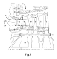
- the first stage comprises a plurality of circumferentially spaced nozzles 14 and buckets 16.
- the nozzles are circumferentially spaced one from the other and fixed about the axis of the rotor.
- the first stage buckets 16 are mounted on the turbine rotor 17.
- a second stage of the turbine 12 is also illustrated, including a plurality of circumferentially spaced nozzles 18 and a plurality of circumferentially spaced buckets 20 mounted on the rotor 17.
- the third stage is also illustrated including a plurality of circumferentially spaced nozzles 22 and buckets 24 mounted on rotor 17. It will be appreciated that the nozzles and buckets lie in the hot gas path 10 of the turbine, the direction of flow of the hot gas through the hot gas path 10 being indicated by the arrow 26.
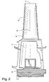
- each bucket 16 is provided, as illustrated in Figure 2, with a platform 30, a shank 32 and an axial entry dovetail 34 for connection with a complementary-shaped mating dovetail, not shown, on the rotor wheel 19. It will also be appreciated that each bucket 16 has a bucket airfoil 36. Thus, each of the buckets 16 has an airfoil profile at any cross-section along the airfoil from the airfoil root to the bucket tip 33.
- the airfoil cooling holes are illustrated.
- the holes are designated in Figures 6 and 7 at 0% span and 100% span by the notation H followed by a hole number.
- the intermediate holes are designated holes H2-H14.
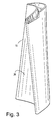
- the holes extend from the shank 32 through airfoil 36 to the tip 33. All of the holes have circular cross-sectional configurations and, as illustrated in Figures 4 and 5, are canted relative to one another and to a radius from the engine centerline.
- the arrangement of the holes H1-H16 is perimetrical, i.e., essentially follows the contours of the pressure and suction sides of the airfoil while cooling hole diameters are constant throughout the length of each of the cooling holes.
- the hole diameter for hole H1 is larger than the hole diameters for holes H2-H16.
- the intermediate holes H2-H14 have a hole diameter in excess of the hole diameters of the trailing edge holes H15 and H16, all as indicated by the Table I below. Additionally, and referring to Figure 8, the intermediate holes H2-H14 are turbulated.
- the holes H2-H14 each have a series of radially inwardly projecting ribs 42 at axially spaced positions along the length of the cooling hole to afford turbulence to the flow of air outwardly along the cooling hole.
- turbulence promoters such as dimples or a roughened surface within the interior surfaces of the intermediate holes H2-H14 may be provided.
- the walls of the leading and trailing edge holes H1 and H15, H16, respectively, are smooth and are not turbulated.
- Table I below provides the specific hole diameters and locations of the holes in an X, Y coordinate system at airfoil profile sections at 5% span, 50% span and 90% span.
- the origin of the X, Y coordinate system is the same origin used in the companion patent application identified above and incorporated by reference.
- holes H3-H11 form a generally airfoil-shaped envelope 50 in Figure 6 at 0% span of the airfoil whereas holes H2-H11 form a generally airfoil-shaped envelope 52 at 100% span.
- both envelopes 50 and 52 are defined by holes on opposite sides of mean camber lines 54 and 56, respectively, extending between leading and trailing edges of the airfoil.
- each first stage bucket airfoil is given a unique set or loci of points in space.
- the loci of points are arrived at by iteration between aerodynamic and mechanical loadings enabling the turbine to run in an efficient, safe and smooth manner.
- the loci which defines the bucket airfoil profile comprises a set of 1000 points relative to the axis of rotation of the turbine.
- a Cartesian coordinate system of X, Y and Z values given in Table II below defines the profile section of the bucket airfoil at various locations along its length.
- the coordinate values for the X and Y coordinates are set forth in inches in Table II although other units of dimensions may be used when the values are appropriately converted.
- the Z values are set forth in Table II in non-dimensional form from 0.05 (5%) span to 0.95 (95% span).
- a Z coordinate value e.g., in inches
- the non-dimensional Z value given in Table II is multiplied by the height of the airfoil 36 in inches.
- the Cartesian coordinate system has orthogonally-related X, Y and Z axes and the X axis lies parallel to the turbine rotor centerline, i.e., the rotary axis and a positive X coordinate value is axial toward the aft, i.e., exhaust end of the turbine.
- the positive Y coordinate value looking aft extends tangentially in the direction of rotation of the rotor and the positive Z coordinate value is generally radially outwardly toward the bucket tip.
- the origins of the Cartesian coordinate systems of Tables I and II are coincident.
- the bucket airfoil profile section at each Z distance along the length of the airfoil can be ascertained.
- each profile section at each distance Z is fixed.
- the airfoil profile sections of the various surface locations between the distances Z are determined by smoothly connecting the adjacent profile sections to one another to form the entire airfoil profile.
- the Table II values for X and Y are generated and shown to four decimal places for determining the profile of the airfoil. The fourth decimal place, however, is not significant and may be rounded up or down. There are typical manufacturing tolerances as well as coatings which must be accounted for in the actual profile of the airfoil. Accordingly, the values for the airfoil profile given in Table II are for a nominal airfoil. It will therefore be appreciated that ⁇ typical manufacturing tolerances, i.e., ⁇ values, including any coating thicknesses, are additive to the X and Y values given in Table II below.
- a distance of ⁇ 0.150 inches in a direction normal to any surface location along the airfoil profile defines an airfoil profile envelope for this particular bucket airfoil design and turbine, i.e., a range of variation between measured points on the actual airfoil surface at nominal cold or room temperature and the ideal position of those points as given in the Table below at the same temperature.
- the bucket airfoil design is robust to this range of variation without impairment of mechanical and aerodynamic functions.
- the root of the bucket airfoil at the midpoint of the platform in a preferred embodiment of the turbine lies at 32.348 inches along a radius from the turbine centerline, i.e., the rotor axis.
- the actual height of the airfoil 36 in a preferred embodiment hereof, that is, the actual Z height of the bucket is 7.075 inches from the root at the midpoint of the platform 30 to tip 33.
- the tip 33 of the bucket 16 in a preferred embodiment lies 39.423 inches along a radius from the turbine centerline 39.
- the airfoil and the locations of the cooling holes are defined relative to one another.
- the coordinate values set forth in Tables I and II may be scaled upwardly or downwardly such that the airfoil profile shape remains unchanged.
- a scaled version of the coordinates in Tables I and II would be represented by X and Y coordinate values of the Tables, and optionally the span locations coordinates of Table I and the non-dimensional Z coordinate values of Table II when converted to inches, multiplied or divided by a constant number.
Landscapes
- Engineering & Computer Science (AREA)
- Mechanical Engineering (AREA)
- General Engineering & Computer Science (AREA)
- Physics & Mathematics (AREA)
- Fluid Mechanics (AREA)
- Turbine Rotor Nozzle Sealing (AREA)
- Detergent Compositions (AREA)
Applications Claiming Priority (2)
| Application Number | Priority Date | Filing Date | Title |
|---|---|---|---|
| US635435 | 2003-08-07 | ||
| US10/635,435 US6923623B2 (en) | 2003-08-07 | 2003-08-07 | Perimeter-cooled turbine bucket airfoil cooling hole location, style and configuration |
Publications (2)
| Publication Number | Publication Date |
|---|---|
| EP1505255A2 true EP1505255A2 (de) | 2005-02-09 |
| EP1505255A3 EP1505255A3 (de) | 2012-06-06 |
Family
ID=33552943
Family Applications (1)
| Application Number | Title | Priority Date | Filing Date |
|---|---|---|---|
| EP04254702A Withdrawn EP1505255A3 (de) | 2003-08-07 | 2004-08-05 | Anordnung von Kühlungsbohrungen von Laufschaufelformen einer am Umfang gekühlten Gasturbine |
Country Status (4)
| Country | Link |
|---|---|
| US (1) | US6923623B2 (de) |
| EP (1) | EP1505255A3 (de) |
| JP (1) | JP4570135B2 (de) |
| CN (1) | CN100436755C (de) |
Cited By (5)
| Publication number | Priority date | Publication date | Assignee | Title |
|---|---|---|---|---|
| FR2859235A1 (fr) * | 2003-09-03 | 2005-03-04 | Gen Electric | Emplacement, modele et configuration des trous de refroidissement du plan de sustentation d'une ailette de turbine |
| WO2011160930A1 (en) | 2010-06-23 | 2011-12-29 | Siemens Aktiengesellschaft | Gas turbine blade |
| US8956700B2 (en) | 2011-10-19 | 2015-02-17 | General Electric Company | Method for adhering a coating to a substrate structure |
| RU2573085C2 (ru) * | 2010-06-23 | 2016-01-20 | Сименс Акциенгезелльшафт | Лопатка газовой турбины |
| CN111720216A (zh) * | 2020-06-24 | 2020-09-29 | 中国航发湖南动力机械研究所 | 发动机装置的装配方法 |
Families Citing this family (33)
| Publication number | Priority date | Publication date | Assignee | Title |
|---|---|---|---|---|
| US7572102B1 (en) | 2006-09-20 | 2009-08-11 | Florida Turbine Technologies, Inc. | Large tapered air cooled turbine blade |
| US7494322B2 (en) * | 2006-10-25 | 2009-02-24 | General Electric Company | Airfoil shape for a compressor |
| US7494323B2 (en) * | 2006-10-25 | 2009-02-24 | General Electric Company | Airfoil shape for a compressor |
| US7494321B2 (en) * | 2006-10-25 | 2009-02-24 | General Electric Company | Airfoil shape for a compressor |
| US7497663B2 (en) * | 2006-10-26 | 2009-03-03 | General Electric Company | Rotor blade profile optimization |
| US8011889B1 (en) * | 2007-09-07 | 2011-09-06 | Florida Turbine Technologies, Inc. | Turbine blade with trailing edge tip corner cooling |
| CN101493017A (zh) * | 2007-09-28 | 2009-07-29 | 通用电气公司 | 用于涡轮机的气冷式叶片 |
| US8147188B2 (en) * | 2007-09-28 | 2012-04-03 | General Electric Company | Air cooled bucket for a turbine |
| US7887295B2 (en) * | 2007-11-08 | 2011-02-15 | General Electric Company | Z-Notch shape for a turbine blade |
| US8087253B2 (en) * | 2008-11-20 | 2012-01-03 | General Electric Company | Methods, apparatus and systems concerning the circumferential clocking of turbine airfoils in relation to combustor cans and the flow of cooling air through the turbine hot gas flowpath |
| CH699999A1 (de) * | 2008-11-26 | 2010-05-31 | Alstom Technology Ltd | Gekühlte schaufel für eine gasturbine. |
| CN101586475B (zh) * | 2008-12-23 | 2011-04-27 | 张金山 | 航空发动机涡轮转子叶片的集束分流式热防护 |
| US8628299B2 (en) * | 2010-01-21 | 2014-01-14 | General Electric Company | System for cooling turbine blades |
| CN102146810A (zh) * | 2010-02-10 | 2011-08-10 | 中国科学院工程热物理研究所 | 利用工质的超临界特性对高温涡轮叶片进行冷却的方法 |
| US8727724B2 (en) * | 2010-04-12 | 2014-05-20 | General Electric Company | Turbine bucket having a radial cooling hole |
| GB201006450D0 (en) * | 2010-04-19 | 2010-06-02 | Rolls Royce Plc | Blades |
| US8568085B2 (en) * | 2010-07-19 | 2013-10-29 | Pratt & Whitney Canada Corp | High pressure turbine vane cooling hole distrubution |
| US8556588B2 (en) | 2011-06-03 | 2013-10-15 | General Electric Company | Airfoil shape for a compressor |
| US9322280B2 (en) * | 2011-08-12 | 2016-04-26 | United Technologies Corporation | Method of measuring turbine blade tip erosion |
| US9115588B2 (en) | 2012-07-02 | 2015-08-25 | United Technologies Corporation | Gas turbine engine turbine blade airfoil profile |
| EP3030750A4 (de) * | 2013-08-05 | 2017-04-26 | United Technologies Corporation | Spitzenkühlung für tragflächenaustrittskanten |
| EP2937512B1 (de) | 2014-04-23 | 2020-05-27 | United Technologies Corporation | Anordnung für ein gasturbinentriebwerk |
| US10107108B2 (en) | 2015-04-29 | 2018-10-23 | General Electric Company | Rotor blade having a flared tip |
| US20170058680A1 (en) * | 2015-09-02 | 2017-03-02 | General Electric Company | Configurations for turbine rotor blade tips |
| US20170107827A1 (en) * | 2015-10-15 | 2017-04-20 | General Electric Company | Turbine blade |
| US20180073370A1 (en) * | 2016-09-14 | 2018-03-15 | Rolls-Royce Plc | Turbine blade cooling |
| US10428666B2 (en) * | 2016-12-12 | 2019-10-01 | United Technologies Corporation | Turbine vane assembly |
| US10443405B2 (en) * | 2017-05-10 | 2019-10-15 | General Electric Company | Rotor blade tip |
| US10989070B2 (en) * | 2018-05-31 | 2021-04-27 | General Electric Company | Shroud for gas turbine engine |
| US10648338B2 (en) * | 2018-09-28 | 2020-05-12 | General Electric Company | Airfoil shape for second stage compressor stator vane |
| US12123319B2 (en) | 2020-12-30 | 2024-10-22 | Ge Infrastructure Technology Llc | Cooling circuit having a bypass conduit for a turbomachine component |
| US12006836B2 (en) | 2021-07-02 | 2024-06-11 | Rtx Corporation | Cooling arrangement for gas turbine engine component |
| US11913353B2 (en) | 2021-08-06 | 2024-02-27 | Rtx Corporation | Airfoil tip arrangement for gas turbine engine |
Family Cites Families (7)
| Publication number | Priority date | Publication date | Assignee | Title |
|---|---|---|---|---|
| JPS55114435A (en) * | 1979-02-24 | 1980-09-03 | Ishikawajima Harima Heavy Ind Co Ltd | Production of air cooled type gas turbine blade |
| CA1190480A (en) * | 1981-03-02 | 1985-07-16 | Westinghouse Electric Corporation | Vane structure having improved cooled operation in stationary combustion turbines |
| JPS59231103A (ja) * | 1983-06-14 | 1984-12-25 | Toshiba Corp | ガスタ−ビン冷却翼 |
| US5117626A (en) * | 1990-09-04 | 1992-06-02 | Westinghouse Electric Corp. | Apparatus for cooling rotating blades in a gas turbine |
| US5712050A (en) * | 1991-09-09 | 1998-01-27 | General Electric Company | Superalloy component with dispersion-containing protective coating |
| US5980209A (en) * | 1997-06-27 | 1999-11-09 | General Electric Co. | Turbine blade with enhanced cooling and profile optimization |
| US6382914B1 (en) * | 2001-02-23 | 2002-05-07 | General Electric Company | Cooling medium transfer passageways in radial cooled turbine blades |
-
2003
- 2003-08-07 US US10/635,435 patent/US6923623B2/en not_active Expired - Lifetime
-
2004
- 2004-08-05 EP EP04254702A patent/EP1505255A3/de not_active Withdrawn
- 2004-08-06 JP JP2004230070A patent/JP4570135B2/ja not_active Expired - Fee Related
- 2004-08-06 CN CNB2004100549956A patent/CN100436755C/zh not_active Expired - Fee Related
Cited By (9)
| Publication number | Priority date | Publication date | Assignee | Title |
|---|---|---|---|---|
| FR2859235A1 (fr) * | 2003-09-03 | 2005-03-04 | Gen Electric | Emplacement, modele et configuration des trous de refroidissement du plan de sustentation d'une ailette de turbine |
| WO2011160930A1 (en) | 2010-06-23 | 2011-12-29 | Siemens Aktiengesellschaft | Gas turbine blade |
| CN103080477A (zh) * | 2010-06-23 | 2013-05-01 | 西门子公司 | 燃气涡轮叶片 |
| US8585351B2 (en) | 2010-06-23 | 2013-11-19 | Ooo Siemens | Gas turbine blade |
| CN103080477B (zh) * | 2010-06-23 | 2015-08-12 | 西门子公司 | 燃气涡轮叶片 |
| RU2573085C2 (ru) * | 2010-06-23 | 2016-01-20 | Сименс Акциенгезелльшафт | Лопатка газовой турбины |
| US8956700B2 (en) | 2011-10-19 | 2015-02-17 | General Electric Company | Method for adhering a coating to a substrate structure |
| CN111720216A (zh) * | 2020-06-24 | 2020-09-29 | 中国航发湖南动力机械研究所 | 发动机装置的装配方法 |
| CN111720216B (zh) * | 2020-06-24 | 2022-02-11 | 中国航发湖南动力机械研究所 | 发动机装置的装配方法 |
Also Published As
| Publication number | Publication date |
|---|---|
| EP1505255A3 (de) | 2012-06-06 |
| JP4570135B2 (ja) | 2010-10-27 |
| CN1580499A (zh) | 2005-02-16 |
| JP2005054804A (ja) | 2005-03-03 |
| US20050031449A1 (en) | 2005-02-10 |
| US6923623B2 (en) | 2005-08-02 |
| CN100436755C (zh) | 2008-11-26 |
Similar Documents
| Publication | Publication Date | Title |
|---|---|---|
| US6923623B2 (en) | Perimeter-cooled turbine bucket airfoil cooling hole location, style and configuration | |
| US6910868B2 (en) | Airfoil shape for a turbine bucket | |
| US6910864B2 (en) | Turbine bucket airfoil cooling hole location, style and configuration | |
| US6857855B1 (en) | Airfoil shape for a turbine bucket | |
| US6779980B1 (en) | Airfoil shape for a turbine bucket | |
| US6769879B1 (en) | Airfoil shape for a turbine bucket | |
| US6881038B1 (en) | Airfoil shape for a turbine bucket | |
| EP1482125A2 (de) | Profilform einer Turbinenschaufel | |
| US6808368B1 (en) | Airfoil shape for a turbine bucket | |
| US6715990B1 (en) | First stage turbine bucket airfoil | |
| US6558122B1 (en) | Second-stage turbine bucket airfoil | |
| US6474948B1 (en) | Third-stage turbine bucket airfoil | |
| US6503059B1 (en) | Fourth-stage turbine bucket airfoil | |
| US6884038B2 (en) | Airfoil shape for a turbine bucket | |
| US7494323B2 (en) | Airfoil shape for a compressor | |
| EP1503037A2 (de) | Schaufelprofil einer Turbinen-Statorschaufel | |
| US20080101955A1 (en) | Airfoil shape for a compressor | |
| US20080101952A1 (en) | Airfoil shape for a compressor | |
| US20080101954A1 (en) | Airfoil shape for a compressor | |
| US20080107535A1 (en) | Airfoil shape for a compressor | |
| US20080101949A1 (en) | Airfoil shape for a compressor | |
| US20080101941A1 (en) | Airfoil shape for a compressor | |
| US20080101947A1 (en) | Airfoil shape for a compressor | |
| US20080101940A1 (en) | Airfoil shape for a compressor | |
| US20080101953A1 (en) | Airfoil shape for a compressor |
Legal Events
| Date | Code | Title | Description |
|---|---|---|---|
| PUAI | Public reference made under article 153(3) epc to a published international application that has entered the european phase |
Free format text: ORIGINAL CODE: 0009012 |
|
| AK | Designated contracting states |
Kind code of ref document: A2 Designated state(s): AT BE BG CH CY CZ DE DK EE ES FI FR GB GR HU IE IT LI LU MC NL PL PT RO SE SI SK TR |
|
| AX | Request for extension of the european patent |
Extension state: AL HR LT LV MK |
|
| PUAL | Search report despatched |
Free format text: ORIGINAL CODE: 0009013 |
|
| AK | Designated contracting states |
Kind code of ref document: A3 Designated state(s): AT BE BG CH CY CZ DE DK EE ES FI FR GB GR HU IE IT LI LU MC NL PL PT RO SE SI SK TR |
|
| AX | Request for extension of the european patent |
Extension state: AL HR LT LV MK |
|
| RIC1 | Information provided on ipc code assigned before grant |
Ipc: F01D 5/14 20060101AFI20120427BHEP |
|
| 17P | Request for examination filed |
Effective date: 20121206 |
|
| AKX | Designation fees paid |
Designated state(s): DE FR GB |
|
| 17Q | First examination report despatched |
Effective date: 20150915 |
|
| STAA | Information on the status of an ep patent application or granted ep patent |
Free format text: STATUS: THE APPLICATION IS DEEMED TO BE WITHDRAWN |
|
| 18D | Application deemed to be withdrawn |
Effective date: 20160126 |