EP1505336B2 - Beleuchtungseinrichtung - Google Patents
Beleuchtungseinrichtung Download PDFInfo
- Publication number
- EP1505336B2 EP1505336B2 EP04017135A EP04017135A EP1505336B2 EP 1505336 B2 EP1505336 B2 EP 1505336B2 EP 04017135 A EP04017135 A EP 04017135A EP 04017135 A EP04017135 A EP 04017135A EP 1505336 B2 EP1505336 B2 EP 1505336B2
- Authority
- EP
- European Patent Office
- Prior art keywords
- lighting device
- foregoing
- circuit board
- light
- printed circuit
- Prior art date
- Legal status (The legal status is an assumption and is not a legal conclusion. Google has not performed a legal analysis and makes no representation as to the accuracy of the status listed.)
- Expired - Lifetime
Links
Images



Classifications
-
- F—MECHANICAL ENGINEERING; LIGHTING; HEATING; WEAPONS; BLASTING
- F21—LIGHTING
- F21V—FUNCTIONAL FEATURES OR DETAILS OF LIGHTING DEVICES OR SYSTEMS THEREOF; STRUCTURAL COMBINATIONS OF LIGHTING DEVICES WITH OTHER ARTICLES, NOT OTHERWISE PROVIDED FOR
- F21V15/00—Protecting lighting devices from damage
- F21V15/01—Housings, e.g. material or assembling of housing parts
-
- F—MECHANICAL ENGINEERING; LIGHTING; HEATING; WEAPONS; BLASTING
- F21—LIGHTING
- F21S—NON-PORTABLE LIGHTING DEVICES; SYSTEMS THEREOF; VEHICLE LIGHTING DEVICES SPECIALLY ADAPTED FOR VEHICLE EXTERIORS
- F21S10/00—Lighting devices or systems producing a varying lighting effect
- F21S10/02—Lighting devices or systems producing a varying lighting effect changing colors
-
- F—MECHANICAL ENGINEERING; LIGHTING; HEATING; WEAPONS; BLASTING
- F21—LIGHTING
- F21V—FUNCTIONAL FEATURES OR DETAILS OF LIGHTING DEVICES OR SYSTEMS THEREOF; STRUCTURAL COMBINATIONS OF LIGHTING DEVICES WITH OTHER ARTICLES, NOT OTHERWISE PROVIDED FOR
- F21V27/00—Cable-stowing arrangements structurally associated with lighting devices, e.g. reels
- F21V27/02—Cable inlets
-
- F—MECHANICAL ENGINEERING; LIGHTING; HEATING; WEAPONS; BLASTING
- F21—LIGHTING
- F21S—NON-PORTABLE LIGHTING DEVICES; SYSTEMS THEREOF; VEHICLE LIGHTING DEVICES SPECIALLY ADAPTED FOR VEHICLE EXTERIORS
- F21S8/00—Lighting devices intended for fixed installation
- F21S8/02—Lighting devices intended for fixed installation of recess-mounted type, e.g. downlighters
-
- F—MECHANICAL ENGINEERING; LIGHTING; HEATING; WEAPONS; BLASTING
- F21—LIGHTING
- F21S—NON-PORTABLE LIGHTING DEVICES; SYSTEMS THEREOF; VEHICLE LIGHTING DEVICES SPECIALLY ADAPTED FOR VEHICLE EXTERIORS
- F21S8/00—Lighting devices intended for fixed installation
- F21S8/02—Lighting devices intended for fixed installation of recess-mounted type, e.g. downlighters
- F21S8/022—Lighting devices intended for fixed installation of recess-mounted type, e.g. downlighters intended to be recessed in a floor or like ground surface, e.g. pavement or false floor
-
- F—MECHANICAL ENGINEERING; LIGHTING; HEATING; WEAPONS; BLASTING
- F21—LIGHTING
- F21W—INDEXING SCHEME ASSOCIATED WITH SUBCLASSES F21K, F21L, F21S and F21V, RELATING TO USES OR APPLICATIONS OF LIGHTING DEVICES OR SYSTEMS
- F21W2131/00—Use or application of lighting devices or systems not provided for in codes F21W2102/00-F21W2121/00
- F21W2131/10—Outdoor lighting
-
- F—MECHANICAL ENGINEERING; LIGHTING; HEATING; WEAPONS; BLASTING
- F21—LIGHTING
- F21W—INDEXING SCHEME ASSOCIATED WITH SUBCLASSES F21K, F21L, F21S and F21V, RELATING TO USES OR APPLICATIONS OF LIGHTING DEVICES OR SYSTEMS
- F21W2131/00—Use or application of lighting devices or systems not provided for in codes F21W2102/00-F21W2121/00
- F21W2131/10—Outdoor lighting
- F21W2131/107—Outdoor lighting of the exterior of buildings
-
- F—MECHANICAL ENGINEERING; LIGHTING; HEATING; WEAPONS; BLASTING
- F21—LIGHTING
- F21Y—INDEXING SCHEME ASSOCIATED WITH SUBCLASSES F21K, F21L, F21S and F21V, RELATING TO THE FORM OR THE KIND OF THE LIGHT SOURCES OR OF THE COLOUR OF THE LIGHT EMITTED
- F21Y2115/00—Light-generating elements of semiconductor light sources
- F21Y2115/10—Light-emitting diodes [LED]
-
- Y—GENERAL TAGGING OF NEW TECHNOLOGICAL DEVELOPMENTS; GENERAL TAGGING OF CROSS-SECTIONAL TECHNOLOGIES SPANNING OVER SEVERAL SECTIONS OF THE IPC; TECHNICAL SUBJECTS COVERED BY FORMER USPC CROSS-REFERENCE ART COLLECTIONS [XRACs] AND DIGESTS
- Y10—TECHNICAL SUBJECTS COVERED BY FORMER USPC
- Y10S—TECHNICAL SUBJECTS COVERED BY FORMER USPC CROSS-REFERENCE ART COLLECTIONS [XRACs] AND DIGESTS
- Y10S362/00—Illumination
- Y10S362/80—Light emitting diode
Definitions
- the present invention is based on a designed according to the preamble of the main claim lighting device.
- Such lighting devices are usually intended to provide inside or outside of buildings for the targeted illumination of their environment or for the illumination of objects directly in their environment and / or for a targeted coupling of light into objects. If such lighting devices z. B. for installation in ceilings or floors, often a very compact design is necessary for easy installation.
- a the preamble of the main claim corresponding lighting device is characterized by the US 5,388,035 known.
- this lighting device several, connectable to the mains, designed as LED bulbs are arranged on a circuit board.
- the circuit board is surrounded by a, a targeted light outlet enabling housing, the housing consists of at least one of the circuit board receiving, a passage opening for the connecting cable having hat-like intermediate part and, the targeted light emission enabling cover part.
- a lighting device has become known in which a plurality of lamps are arranged on a connectable to the power supply circuit board.
- the circuit board is surrounded by a, a targeted light emission enabling housing, which protects the bulbs from aggressive environmental conditions such. As moisture, dust, mechanical stress, etc. effectively protects.
- the present invention is therefore based on the object to provide a lighting device whose housing safely protects the functional elements against aggressive environmental conditions or the expected mechanical loads and is designed to be particularly compact.
- such a lighting device mainly consists of a light-emitting device 1 having printed circuit board 2, which is protectively surrounded by a housing.
- the housing essentially consists of a body forming the outer body 3, a circuit board 2 receiving, a through opening 4 for the connection cable 5 having hat-shaped intermediate part 6 and a targeted light emission enabling cover part 7, and an annular aperture part 8 fixed thereto.
- the circuit board 2 is formed horseshoe-shaped, so that a receiving or lead-in space is formed to save space for the two connection cable 5.
- the circuit board 2 is equipped with three designed as LED bulbs 1.
- the three bulbs 1 emit light in the colors red, green and blue.
- a -for simplicity not shown- electronic control device for targeted control of the LED designed as a light source 1 is present on the circuit board 2 . So can in a simple way z. B. any mixed colors, lighting effects, etc. are generated.
- these are glued zugentlastend with the intermediate part 6.
- the intermediate part 6 is supported with its bottom on limiting tabs 10, which are integrally formed on the bottom of the base part 3.
- the printed circuit board 2 is received by an annular groove 11 of the intermediate part 6, wherein the two connecting cables 5 are guided through the passage opening 4 to the outside.
- the lid part 7 is supported with its outer edge region 12 on the outer annular surface 13 of the intermediate part 6 from. In addition, this comes with his molded coupling ring 14 on the survey 15 of the intermediate part 6 to the plant.
- An integrally formed collar 16 also comes positively to the inner wall 17 of the intermediate part 6 to the plant.
- the three receiving chambers 18 are formed in the bottom of the lid part 7.
- the three lamps 1 designed as LED emit their light laterally, so that a good coupling of the radiated light over the coupling ring 14 into the cover part 7 is ensured.
- the targeted decoupling of the light takes place via an outcoupling region 19 of the cover part 7, which can be shaped as desired, wherein the screen part 8 is to be designed in accordance with the shape of the decoupling region 19.
- the diaphragm part 8 is annular.
- the particularly sturdy housing protects the sensitive components well before the expected in use loads or aggressive environmental conditions.
- the base part 3 is made of surface-treated metal, the intermediate part 6 and the panel part 8 made of opaque plastic, as well as the cover part 7 made entirely of translucent plastic.
- the two boundary tabs 10 of the base 3 are separated by two oppositely disposed recesses 20 from each other.
- the size of the two recesses 20 are each dimensioned so that during the installation process of the lighting device at the intended installation the existing from the intermediate part 6, the circuit board 2 and the cover part 7 assembly with the two connected connection cable 5 can be passed through the housing part 3 from below , in particular from Fig. 5 evident.
Landscapes
- Engineering & Computer Science (AREA)
- General Engineering & Computer Science (AREA)
- Arrangement Of Elements, Cooling, Sealing, Or The Like Of Lighting Devices (AREA)
- Non-Portable Lighting Devices Or Systems Thereof (AREA)
- Vehicle Body Suspensions (AREA)
- Polarising Elements (AREA)
- Seal Device For Vehicle (AREA)
- Liquid Crystal Substances (AREA)
- Pressure Welding/Diffusion-Bonding (AREA)
Description
- Die vorliegende Erfindung geht von einer gemäß dem Oberbegriff des Hauptanspruches konzipierten Beleuchtungseinrichtung aus.
- Derartige Beleuchtungseinrichtungen sind in der Regel dafür vorgesehen, innerhalb bzw. außerhalb von Gebäuden für die gezielte Ausleuchtung ihrer Umgebung bzw. für die Anleuchtung von direkt in ihrer Umgebung befindlicher Gegenstände und/oder für eine gezielte Einkoppelung von Licht in Gegenstände zu sorgen. Werden solche Beleuchtungseinrichtungen z. B. zum Einbau in Decken oder Fußböden verwand, ist zum problemlosen Einbau oftmals eine sehr kompakte Bauweise notwendig.
- Eine dem Oberbegriff des Hauptanspruches entsprechende Beleuchtungseinrichtung ist durch die
US 5,388,035 bekannt geworden. Bei dieser Beleuchtungseinrichtung sind mehrere, an das Versorgungsnetz anschließbare, als LED ausgebildete Leuchtmittel auf einer Leiterplatte angeordnet. Die Leiterplatte ist von einem, einen gezielten Lichtaustritt ermöglichenden Gehäuse umgeben, wobei das Gehäuse zumindest aus einem die Leiterplatte aufnehmenden, eine Durchführöffnung für die Anschlusskabel aufweisenden hutartigen Zwischenteil und einem, den gezielten Lichtaustritt ermöglichenden Deckelteil besteht. - Des Weiteren ist durch die
DE 100 26 661 A1 eine Beleuchtungseinrichtung bekannt geworden, bei der mehrere Leuchtmittel auf einer, an das Versorgungsnetz anschließbaren Leiterplatte angeordnet sind. Die Leiterplatte ist von einem, einen gezielten Lichtaustritt ermöglichenden Gehäuse umgeben, welches die Leuchtmittel vor aggressiven Umgebungsbedingungen, wie z. B. Feuchtigkeit, Staub, mechanischen Belastungen usw. wirkungsvoll schützt. - Derartig ausgebildete Beleuchtungseinrichtungen bauen jedoch vergleichsweise groß, was insbesondere beim Einbau in Decken und Fußböden von Gebäuden hinderlich sein kann.
- Der vorliegenden Erfindung liegt deshalb die Aufgabe zugrunde, eine Beleuchtungseinrichtung zu schaffen, dessen Gehäuse die Funktionselemente sicher geschützt vor aggressiven Umgebungsbedingungen bzw. den zu erwartenden mechanische Belastungen aufnimmt und dabei besonders kompakt ausgeführt ist.
- Diese Aufgabe wird durch die im Hauptanspruch angegebenen Merkmale gelöst. Bei einer solchermaßen ausgebildeten Beleuchtungseinrichtung ist besonders vorteilhaft, dass sich eine solche Beleuchtungseinrichtung auf preisgünstige Art und Weise herstellen und problemlos, sowie formschön in seine Umgebung, wie Decken, Fußböden und Wände integrieren lässt.
- Weitere vorteilhafte Ausgestaltungen des erfindungsgemäßen Gegenstandes sind in den Unteransprüchen angegeben. Anhand eines Ausführungsbeispieles sei der erfindungsgemäße Gegenstand näher beschrieben, dabei zeigen:
- Fig. 1:
- prinziphaft eine Beleuchtungseinrichtung räumlich in Explosionsdarstellung;
- Fig. 2:
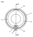
- eine Unteransicht der Beleuchtungseinrichtung gemäß
Figur 1 ; - Fig. 3:
- einen Vollschnitt der Beleuchtungseinrichtung entsprechend Linie A-A gemäß
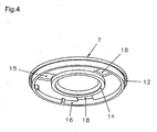
Figur 2 ; - Fig. 4:
- eine Unteransicht des Deckelteils der Beleuchtungseinrichtung;
- Fig. 5:
- prinziphaft einen geeigneten Ablauf für den Einbau der Beleuchtungseinrichtung vor Ort.
- Wie aus den Figuren hervorgeht, besteht eine solche Beleuchtungseinrichtung hauptsächlich aus einer die Leuchtmittel 1 aufweisenden Leiterplatte 2, welche schützend von einem Gehäuse umgeben ist.
- Wie des weiteren aus den Figuren hervorgeht, besteht das Gehäuse im Wesentlichen aus einem den Außenkörper bildenden Grundteil 3, einem die Leiterplatte 2 aufnehmenden, eine Durchführöffnung 4 für die Anschlusskabel 5 aufweisenden, hutartig ausgebildeten Zwischenteil 6 und einem den gezielten Lichtaustritt ermöglichenden Deckelteil 7, sowie einem daran festgelegten ringförmigen Blendenteil 8.
- Wie insbesondere aus
Fig. 1 hervorgeht, ist die Leiterplatte 2 hufeisenförmig ausgebildet, so dass für die beiden Anschlusskabel 5 platzsparend ein Aufnahme- bzw. Durchführraum gebildet ist. Die Leiterplatte 2 ist mit drei als LED ausgeführten Leuchtmitteln 1 bestückt. Die drei Leuchtmittel 1 strahlen Licht in den Farben rot, grün und blau ab. Außerdem ist auf der Leiterplatte 2 eine -der Einfachheit halber nicht dargestellte- elektronische Steuereinrichtung zur gezielten Ansteuerung der als LED ausgebildeten Leuchtmittel 1 vorhanden. So können auf einfache Art und Weise z. B. beliebige Mischfarben, Lichteffekte usw. erzeugt werden. Um dauerhaft eine sichere Kontaktierung der beiden Anschlusskabel 5 mit der Leiterplatte 2 zu gewährleisten, werden diese zugentlastend mit dem Zwischenteil 6 verklebt. - Wie des weiteren insbesondere aus
Fig. 1 undFig. 3 hervorgeht, stützt sich nach der kompletten Montage der Beleuchtungseinrichtung das Zwischenteil 6 mit seinem Boden an Begrenzungslaschen 10 ab, die an den Boden des Grundteils 3 angeformt sind. Die Leiterplatte 2 wird von einer Ringnut 11 des Zwischenteiles 6 aufgenommen, wobei die beiden Anschlusskabel 5 durch die Durchführöffnung 4 nach außen geführt sind. Wie insbesondere ausFig. 1 ,Fig. 3 undFig. 4 hervorgeht, stützt sich das Deckelteil 7 mit seinem äußeren Randbereich 12 an der äußeren Ringfläche 13 des Zwischenteils 6 ab. Außerdem kommt dieses mit seinem angeformten Einkoppelring 14 auf der Erhebung 15 des Zwischenteils 6 zur Anlage. Ein angeformter Kragen 16 kommt außerdem formschlüssig an der Innenwandung 17 des Zwischenteils 6 zur Anlage. Zur platzsparenden Aufnahme der drei als LED ausgebildeten Leuchtmittel 1 sind drei Aufnahmekammern 18 in die Unterseite des Deckelteils 7 eingeformt. Die drei als LED ausgeführten Leuchtmittel 1 strahlen ihr Licht seitlich ab, so dass eine gute Einkopplung des abgestrahlten Lichts über den Einkoppelring 14 in das Deckelteil 7 gewährleistet ist. Die gezielte Auskopplung des Lichts erfolgt über einen beliebig zu gestaltenden Auskoppelbereich 19 des Deckelteils 7, wobei das Blendenteil 8 entsprechend der Form des Auskoppelbereiches 19 zu gestalten ist. In dem vorliegenden Fall, ist deshalb das Blendenteil 8 ringförmig ausgebildet. Auf einfache und preisgünstige Art und Weise ist somit eine besonders kompakt bauende, formschöne Beleuchtungseinrichtung realisiert, wobei das besonders stabil ausgeführte Gehäuse die empfindlichen Bauteile gut vor den im Gebrauch zu erwartenden Belastungen bzw. aggressiven Umgebungsbedingungen schützt. - Um insbesondere den Funktionsanforderungen bzw. Belastungen als Einbauleuchte in Böden, wie Parkett, Teppich, Laminat usw. sowie in Decken und Wänden bzw. eben so gut auch als Aufbauleuchte zu genügen, ist das Grundteil 3 aus oberflächenveredelten Metall, das Zwischenteil 6 und das Blendenteil 8 aus lichtundurchlässigem Kunststoff, sowie das Deckelteil 7 insgesamt aus lichtdurchlässigem Kunststoff hergestellt.
- Die beiden Begrenzungslaschen 10 des Grundteils 3 sind durch zwei gegenüberliegend angeordnete Ausnehmungen 20 voneinander getrennt. Die Größe der beiden Ausnehmungen 20 sind dabei jeweils so bemessen, dass beim Einbauvorgang der Beleuchtungseinrichtung am vorgesehenen Einbauort die aus dem Zwischenteil 6, der Leiterplatte 2 und dem Deckelteil 7 bestehende Baugruppe mit den beiden angeschlossenen Anschlusskabel 5 von unten durch das Gehäuseteil 3 hindurchgeführt werden kann, wie insbesondere aus
Fig. 5 hervorgeht.
Claims (12)
- Beleuchtungseinrichtung mit mehreren auf einer Leiterplatte (2) angeordneten, über diese an das Versorgungsnetz anschließbaren Leuchtmitteln (1), wobei- die Leiterplatte (2) von einem, einen gezielten Lichtaustritt ermöglichenden Gehäuse umgeben ist;- wobei das Gehäuse zumindest aus einem ringförmigen Grundteil (3), einem die Leiterplatte (2) aufnehmenden, eine Durchführöffnung für die Anschlusskabel (5) aufweisenden hutartigen Zwischenteil (6) und einem, den gezielten Lichtaustritt ermöglichenden Deckelteil (7) besteht,
dadurch gekennzeichnet, dass- das Zwischenteil (6) eine Erhebung (15) und eine Ringnut (11) aufweist;- die Leiterplatte (2) als geschlossener Ring oder hufeisenförmig ausgebildet ist;- und dass die Leiterplatte (2) von der tieferliegenden Ringnut (11) des Zwischenteiles (6) aufgenommen ist. - Beleuchtungseinrichtung nach einem der vorhergehenden Ansprüche, dadurch gekennzeichnet, dass zumindest an der Leiterplatte (2) Zugentlastungsmittel für die Anschlusskabel (5) vorhanden sind.
- Beleuchtungseinrichtung nach einem der vorhergehenden Ansprüche, dadurch gekennzeichnet dass zumindest am Zwischenteil (6) des Gehäuses Zugentlastungsmittel für die Anschlusskabel (5) vorhanden sind.
- Beleuchtungseinrichtung nach einem der vorhergehenden Ansprüche, dadurch gekennzeichnet dass dem, den gezielten Lichtaustritt ermöglichenden Deckelteil (7) zumindest ein Blendenteil (8) zuzuordnen ist.
- Beleuchtungseinrichtung nach einem der vorhergehenden Ansprüche, dadurch gekennzeichnet dass zumindest der Lichtaustrittsbereich (19) des Deckelteils (7) aus transparentem Kunststoff besteht.
- Beleuchtungseinrichtung nach einem der vorhergehenden Ansprüche, dadurch gekennzeichnet dass der Lichtaustrittsbereich (19) des Deckelteils (7) zur gezielten Beeinflussung des Lichtaustrittes eine Lichtauskoppelstruktur aufweist.
- Beleuchtungseinrichtung nach einem der vorhergehenden Ansprüche, dadurch gekennzeichnet dass zumindest eines der auf der Leiterplatte (2) angeordneten Leuchtmittel (1) als LED ausgebildet ist.
- Beleuchtungseinrichtung nach einem der vorhergehenden Ansprüche, dadurch gekennzeichnet dass die Leuchtmittel (1) Licht in zumindest zwei verschiedenen Lichtfarben abstrahlen.
- Beleuchtungseinrichtung nach einem der vorhergehenden Ansprüche, dadurch gekennzeichnet, dass die Leuchtmittel (1) mit einer Steuerungseinrichtung in Verbindung stehen, wodurch diese gezielt zur Erzeugung von Lichteffekten ansteuerbar sind.
- Beleuchtungseinrichtung nach einem der vorhergehenden Ansprüche, dadurch gekennzeichnet dass zumindest ein Teil der Steuerungseinrichtung auf der Leiterplatte (2) angeordnet ist.
- Beleuchtungseinrichtung nach einem der vorhergehenden Ansprüche, dadurch gekennzeichnet dass zumindest ein Teil der Steuerungseinrichtung ortsfern angeordnet ist.
- Beleuchtungseinrichtung nach einem der vorhergehenden Ansprüche, dadurch gekennzeichnet dass an das Grundteil (3) zwei Begrenzungslaschen (10) angeformt sind.
Priority Applications (1)
| Application Number | Priority Date | Filing Date | Title |
|---|---|---|---|
| PL04017135T PL1505336T3 (pl) | 2003-07-31 | 2004-07-21 | Oprawa oświetleniowa |
Applications Claiming Priority (2)
| Application Number | Priority Date | Filing Date | Title |
|---|---|---|---|
| DE10334970 | 2003-07-31 | ||
| DE10334970A DE10334970B3 (de) | 2003-07-31 | 2003-07-31 | Beleuchtungseinrichtung |
Publications (4)
| Publication Number | Publication Date |
|---|---|
| EP1505336A2 EP1505336A2 (de) | 2005-02-09 |
| EP1505336A3 EP1505336A3 (de) | 2007-03-28 |
| EP1505336B1 EP1505336B1 (de) | 2008-02-06 |
| EP1505336B2 true EP1505336B2 (de) | 2012-06-20 |
Family
ID=33547044
Family Applications (1)
| Application Number | Title | Priority Date | Filing Date |
|---|---|---|---|
| EP04017135A Expired - Lifetime EP1505336B2 (de) | 2003-07-31 | 2004-07-21 | Beleuchtungseinrichtung |
Country Status (8)
| Country | Link |
|---|---|
| US (1) | US7025477B2 (de) |
| EP (1) | EP1505336B2 (de) |
| AT (1) | ATE385557T1 (de) |
| DE (3) | DE10334970B3 (de) |
| DK (1) | DK1505336T3 (de) |
| ES (1) | ES2300679T3 (de) |
| PL (1) | PL1505336T3 (de) |
| PT (1) | PT1505336E (de) |
Families Citing this family (59)
| Publication number | Priority date | Publication date | Assignee | Title |
|---|---|---|---|---|
| US20080029141A1 (en) * | 2006-08-04 | 2008-02-07 | Grand Pre David M | Portable shelter lighting system |
| GB2455049B (en) * | 2007-09-10 | 2012-10-10 | Benchmark Electronics Ltd | Low profile LED lighting |
| ES2820846T3 (es) * | 2007-09-21 | 2021-04-22 | Signify Holding Bv | Una lámpara que tiene miembros de contacto en su borde circundante y un portalámparas |
| US7854616B2 (en) * | 2007-10-12 | 2010-12-21 | The L.D. Kichler Co. | Positionable lighting systems and methods |
| US8251552B2 (en) * | 2007-10-24 | 2012-08-28 | Lsi Industries, Inc. | Lighting apparatus and connector plate |
| TWM333511U (en) * | 2007-11-07 | 2008-06-01 | Itw Electronic Business Asia Co Ltd | The screwed and inserted fastener structure with luminous source |
| US8353611B2 (en) * | 2007-11-07 | 2013-01-15 | Itw Electronic Business Asia Co. Ltd. | Fastener with illuminator |
| USD633649S1 (en) | 2008-03-31 | 2011-03-01 | Cooper Technologies Company | LED light fixture |
| DE102008036475A1 (de) * | 2008-08-05 | 2010-02-11 | Zumtobel Lighting Gmbh | Vorrichtung zur Halterung einer Lampenfassung |
| USD641520S1 (en) * | 2009-10-22 | 2011-07-12 | Once Innovations, Inc. | LED downlight with trim and spacers |
| USD624691S1 (en) * | 2009-12-29 | 2010-09-28 | Cordelia Lighting, Inc. | Recessed baffle trim |
| US20120057344A1 (en) * | 2010-09-08 | 2012-03-08 | Robert Wang | Led disc lamp |
| US9105206B2 (en) * | 2010-12-23 | 2015-08-11 | Cree, Inc. | LED-illuminated sign |
| USD711582S1 (en) * | 2011-09-28 | 2014-08-19 | Wavesquare Inc. | Lighting element |
| US9151477B2 (en) | 2012-02-03 | 2015-10-06 | Cree, Inc. | Lighting device and method of installing light emitter |
| US9151457B2 (en) | 2012-02-03 | 2015-10-06 | Cree, Inc. | Lighting device and method of installing light emitter |
| US9310038B2 (en) | 2012-03-23 | 2016-04-12 | Cree, Inc. | LED fixture with integrated driver circuitry |
| US10054274B2 (en) | 2012-03-23 | 2018-08-21 | Cree, Inc. | Direct attach ceiling-mounted solid state downlights |
| WO2013164035A1 (de) * | 2012-05-04 | 2013-11-07 | Siemens Aktiengesellschaft | Leuchteinrichtung |
| USD700992S1 (en) * | 2012-08-28 | 2014-03-11 | Ingenuity Inventions, LLC | Flashing light assembly |
| JP6135908B2 (ja) * | 2013-01-22 | 2017-05-31 | パナソニックIpマネジメント株式会社 | 照明用光源及び照明装置 |
| ITAN20130112A1 (it) * | 2013-06-25 | 2014-12-26 | Cromplast S R L | Faretto a led perfezionato. |
| US10753558B2 (en) | 2013-07-05 | 2020-08-25 | DMF, Inc. | Lighting apparatus and methods |
| US11060705B1 (en) | 2013-07-05 | 2021-07-13 | DMF, Inc. | Compact lighting apparatus with AC to DC converter and integrated electrical connector |
| US10563850B2 (en) | 2015-04-22 | 2020-02-18 | DMF, Inc. | Outer casing for a recessed lighting fixture |
| US11435064B1 (en) | 2013-07-05 | 2022-09-06 | DMF, Inc. | Integrated lighting module |
| US10551044B2 (en) | 2015-11-16 | 2020-02-04 | DMF, Inc. | Recessed lighting assembly |
| US9964266B2 (en) | 2013-07-05 | 2018-05-08 | DMF, Inc. | Unified driver and light source assembly for recessed lighting |
| US11255497B2 (en) | 2013-07-05 | 2022-02-22 | DMF, Inc. | Adjustable electrical apparatus with hangar bars for installation in a building |
| US10139059B2 (en) | 2014-02-18 | 2018-11-27 | DMF, Inc. | Adjustable compact recessed lighting assembly with hangar bars |
| CA3102022C (en) | 2015-05-29 | 2023-04-25 | DMF, Inc. | Lighting module for recessed lighting systems |
| US10012354B2 (en) | 2015-06-26 | 2018-07-03 | Cree, Inc. | Adjustable retrofit LED troffer |
| USD851046S1 (en) | 2015-10-05 | 2019-06-11 | DMF, Inc. | Electrical Junction Box |
| AU2016203751B2 (en) * | 2016-06-06 | 2022-01-20 | The Boeing Company | Method and system for resin infusing a composite preform |
| CN106455302A (zh) * | 2016-11-18 | 2017-02-22 | 苏州艾克威尔科技有限公司 | 一种用于光明灯的异形电路板 |
| US10488000B2 (en) | 2017-06-22 | 2019-11-26 | DMF, Inc. | Thin profile surface mount lighting apparatus |
| USD905327S1 (en) | 2018-05-17 | 2020-12-15 | DMF, Inc. | Light fixture |
| WO2018237294A2 (en) | 2017-06-22 | 2018-12-27 | DMF, Inc. | Thin profile surface mount lighting apparatus |
| CN107143786A (zh) * | 2017-07-10 | 2017-09-08 | 广东拿斯特(国际)照明有限公司 | 一种防水led地埋灯 |
| US11067231B2 (en) | 2017-08-28 | 2021-07-20 | DMF, Inc. | Alternate junction box and arrangement for lighting apparatus |
| CN111670322B (zh) | 2017-11-28 | 2022-04-26 | Dmf股份有限公司 | 可调整的吊架杆组合件 |
| CA3087187A1 (en) | 2017-12-27 | 2019-07-04 | DMF, Inc. | Methods and apparatus for adjusting a luminaire |
| USD904671S1 (en) * | 2018-05-08 | 2020-12-08 | Danyel Verdi | Lighting fixture accessory |
| USD904670S1 (en) * | 2018-05-08 | 2020-12-08 | Danyel Verdi | Lighting fixture accessory |
| USD877957S1 (en) | 2018-05-24 | 2020-03-10 | DMF Inc. | Light fixture |
| CA3103255A1 (en) | 2018-06-11 | 2019-12-19 | DMF, Inc. | A polymer housing for a recessed lighting system and methods for using same |
| USD903605S1 (en) | 2018-06-12 | 2020-12-01 | DMF, Inc. | Plastic deep electrical junction box |
| CA3115146A1 (en) | 2018-10-02 | 2020-04-09 | Ver Lighting Llc | A bar hanger assembly with mating telescoping bars |
| USD1012864S1 (en) | 2019-01-29 | 2024-01-30 | DMF, Inc. | Portion of a plastic deep electrical junction box |
| USD901398S1 (en) | 2019-01-29 | 2020-11-10 | DMF, Inc. | Plastic deep electrical junction box |
| USD966877S1 (en) | 2019-03-14 | 2022-10-18 | Ver Lighting Llc | Hanger bar for a hanger bar assembly |
| CA3154491A1 (en) | 2019-09-12 | 2021-03-18 | DMF, Inc. | Miniature lighting module and lighting fixtures using same |
| CN112555722A (zh) * | 2020-03-03 | 2021-03-26 | 深圳市维天科技有限公司 | 吸顶灯 |
| US12203631B2 (en) | 2020-07-16 | 2025-01-21 | DMF, Inc. | Round metal housing for a lighting system |
| WO2022016047A1 (en) * | 2020-07-17 | 2022-01-20 | Sloan Valve Company | Light ring for plumbing fixtures |
| USD990030S1 (en) | 2020-07-17 | 2023-06-20 | DMF, Inc. | Housing for a lighting system |
| CA3124987A1 (en) | 2020-07-17 | 2022-01-17 | DMF, Inc. | Bar hanger assembly with crossmembers and housing assemblies using same |
| CA3124976A1 (en) | 2020-07-17 | 2022-01-17 | DMF, Inc. | Polymer housing for a lighting system and methods for using same |
| US11585517B2 (en) | 2020-07-23 | 2023-02-21 | DMF, Inc. | Lighting module having field-replaceable optics, improved cooling, and tool-less mounting features |
Citations (8)
| Publication number | Priority date | Publication date | Assignee | Title |
|---|---|---|---|---|
| DE29605901U1 (de) † | 1996-03-29 | 1996-06-05 | Shen-Ko, Tseng, Jenn, Taipeh | Leuchtrollen für Rollschuhe |
| US5580163A (en) † | 1994-07-20 | 1996-12-03 | August Technology Corporation | Focusing light source with flexible mount for multiple light-emitting elements |
| DE19747980A1 (de) † | 1997-10-30 | 1999-05-06 | Wts Kereskedelmi Es Szolgaltat | Beleuchtungskörper für Schwimmbäder und ähnliches |
| DE19809253A1 (de) † | 1998-03-05 | 1999-09-09 | Aqua Signal Ag | Unterflurleuchte und Gruppe von Unterflurleuchten |
| DE19847884A1 (de) † | 1998-10-20 | 2000-04-27 | Hella Kg Hueck & Co | Innenleuchte mit Belüftungsdüse für einen Fahrzeuginnenraum |
| US6454437B1 (en) † | 1999-07-28 | 2002-09-24 | William Kelly | Ring lighting |
| DE10137472A1 (de) † | 2001-08-02 | 2003-02-13 | Theodor Rusler | Quellstein-und Springbrunnenleuchte |
| KR20030030805A (ko) † | 2001-10-12 | 2003-04-18 | 윤창한 | 링형 발광다이오드 집합 전구 |
Family Cites Families (15)
| Publication number | Priority date | Publication date | Assignee | Title |
|---|---|---|---|---|
| DE3725777C1 (de) * | 1987-08-04 | 1988-12-22 | Josef 4040 Neuss De Franken | |
| US5457450A (en) * | 1993-04-29 | 1995-10-10 | R & M Deese Inc. | LED traffic signal light with automatic low-line voltage compensating circuit |
| US5388035A (en) * | 1993-07-23 | 1995-02-07 | Federal-Mogul Corporation | Automotive marker lamp |
| US5632551A (en) * | 1994-07-18 | 1997-05-27 | Grote Industries, Inc. | LED vehicle lamp assembly |
| US5565839A (en) * | 1995-02-16 | 1996-10-15 | Grafon Corporartion | Battery-powered, portable flashing superluminescent light-emitting diode safety warning light |
| DE19512130A1 (de) * | 1995-03-31 | 1996-10-02 | Patent Treuhand Ges Fuer Elektrische Gluehlampen Mbh | Betriebsgerät für eine elektrische Lampe |
| US6019493A (en) * | 1998-03-13 | 2000-02-01 | Kuo; Jeffrey | High efficiency light for use in a traffic signal light, using LED's |
| EP1046196B9 (de) * | 1998-09-28 | 2013-01-09 | Koninklijke Philips Electronics N.V. | Beleuchtungsanordnung |
| DE29921156U1 (de) * | 1998-12-02 | 2000-04-20 | ERCO Leuchten GmbH, 58507 Lüdenscheid | Leuchte nach Art einer Signal- und/oder Orientierungsleuchte |
| DE19919080A1 (de) * | 1999-04-27 | 2000-11-02 | Insta Elektro Gmbh & Co Kg | Beleuchtungseinrichtung |
| DE19926561A1 (de) * | 1999-06-11 | 2000-12-14 | Diehl Stiftung & Co | Strahler, insbesondere Leseleuchte in Kabinen von Fahrzeugen |
| FR2806680B1 (fr) * | 2000-03-24 | 2002-09-06 | Michel Jambor | Feu de signalisation pour vehicule |
| DE10026661A1 (de) * | 2000-05-29 | 2001-12-06 | Insta Elektro Gmbh & Co Kg | Universelle LED-Lampe für Innen- und Außenleuchten im Netzbetrieb |
| US6491413B1 (en) * | 2000-07-31 | 2002-12-10 | Lusa Lighting International | High voltage (line) under-cabinet lighting fixture |
| DE20302614U1 (de) * | 2003-02-17 | 2003-05-08 | ASPÖCK Systems Fahrzeugelektrik Ges.m.b.H. & Co KG, Peuerbach | Positionsleuchte für Fahrzeuge |
-
2003
- 2003-07-31 DE DE10334970A patent/DE10334970B3/de not_active Expired - Fee Related
-
2004
- 2004-07-21 AT AT04017135T patent/ATE385557T1/de not_active IP Right Cessation
- 2004-07-21 DK DK04017135T patent/DK1505336T3/da active
- 2004-07-21 DE DE502004006118T patent/DE502004006118D1/de not_active Expired - Lifetime
- 2004-07-21 DE DE202004021550U patent/DE202004021550U1/de not_active Expired - Lifetime
- 2004-07-21 EP EP04017135A patent/EP1505336B2/de not_active Expired - Lifetime
- 2004-07-21 ES ES04017135T patent/ES2300679T3/es not_active Expired - Lifetime
- 2004-07-21 PL PL04017135T patent/PL1505336T3/pl unknown
- 2004-07-21 PT PT04017135T patent/PT1505336E/pt unknown
- 2004-07-30 US US10/902,576 patent/US7025477B2/en not_active Expired - Fee Related
Patent Citations (8)
| Publication number | Priority date | Publication date | Assignee | Title |
|---|---|---|---|---|
| US5580163A (en) † | 1994-07-20 | 1996-12-03 | August Technology Corporation | Focusing light source with flexible mount for multiple light-emitting elements |
| DE29605901U1 (de) † | 1996-03-29 | 1996-06-05 | Shen-Ko, Tseng, Jenn, Taipeh | Leuchtrollen für Rollschuhe |
| DE19747980A1 (de) † | 1997-10-30 | 1999-05-06 | Wts Kereskedelmi Es Szolgaltat | Beleuchtungskörper für Schwimmbäder und ähnliches |
| DE19809253A1 (de) † | 1998-03-05 | 1999-09-09 | Aqua Signal Ag | Unterflurleuchte und Gruppe von Unterflurleuchten |
| DE19847884A1 (de) † | 1998-10-20 | 2000-04-27 | Hella Kg Hueck & Co | Innenleuchte mit Belüftungsdüse für einen Fahrzeuginnenraum |
| US6454437B1 (en) † | 1999-07-28 | 2002-09-24 | William Kelly | Ring lighting |
| DE10137472A1 (de) † | 2001-08-02 | 2003-02-13 | Theodor Rusler | Quellstein-und Springbrunnenleuchte |
| KR20030030805A (ko) † | 2001-10-12 | 2003-04-18 | 윤창한 | 링형 발광다이오드 집합 전구 |
Also Published As
| Publication number | Publication date |
|---|---|
| ES2300679T3 (es) | 2008-06-16 |
| DK1505336T3 (da) | 2008-06-09 |
| PL1505336T3 (pl) | 2008-07-31 |
| DE502004006118D1 (de) | 2008-03-20 |
| PT1505336E (pt) | 2008-04-29 |
| ATE385557T1 (de) | 2008-02-15 |
| US7025477B2 (en) | 2006-04-11 |
| EP1505336B1 (de) | 2008-02-06 |
| EP1505336A3 (de) | 2007-03-28 |
| DE202004021550U1 (de) | 2008-12-11 |
| EP1505336A2 (de) | 2005-02-09 |
| US20050047131A1 (en) | 2005-03-03 |
| DE10334970B3 (de) | 2005-04-28 |
Similar Documents
| Publication | Publication Date | Title |
|---|---|---|
| EP1505336B1 (de) | Beleuchtungseinrichtung | |
| DE102009014514B4 (de) | Beleuchtungseinrichtung | |
| EP1843081B1 (de) | Leuchte, insbesondere Raumleuchte | |
| DE10344824A1 (de) | Fahrzeuginnenbeleuchtung | |
| DE102007018177B3 (de) | Steckdose mit Orientierungsbeleuchtung | |
| EP2851609B1 (de) | Beleuchtungseinrichtung | |
| DE102007046818B4 (de) | Elektrische Steckdose | |
| DE202017103604U1 (de) | Beleuchtungseinrichtung | |
| DE102011054266B3 (de) | Elektrische Schutzkontaktsteckdose | |
| DE102009031586B3 (de) | Elektrisches Installationsgerät | |
| EP2518848B1 (de) | Rahmen für elektrisches Installationsgerät. | |
| DE202008013198U1 (de) | Beleuchtungseinrichtung | |
| EP2502783B1 (de) | Befestigungseinrichtung für eine Zusatzmatte | |
| DE202012104567U1 (de) | Beleuchtungsanordnung | |
| DE202011110559U1 (de) | Beleuchtungseinrichtung | |
| DE102015106421A1 (de) | Beleuchtungslichtquelle und Beleuchtungsvorrichtung | |
| DE102004020314B4 (de) | Sprech- und/oder Videoeinrichtung | |
| DE202014102936U1 (de) | Beleuchtungseinrichtung | |
| EP1988615B1 (de) | Unterputz-Steckdose mit Leuchtmittelmodul | |
| DE10232894A1 (de) | Leuchte mit mindestens einer Leuchtdiode als Leuchtmittel | |
| DE202008004681U1 (de) | Elektrisches Installationsgerät für die Unterputzmontage | |
| DE202014102935U1 (de) | Beleuchtungseinrichtung | |
| DE102016107896A1 (de) | Leuchte für Möbel | |
| EP4628681A1 (de) | Beleuchtungseinrichtung, insbesondere für schwimmbecken und whirlpools | |
| DE19640317C2 (de) | Paneelleuchte |
Legal Events
| Date | Code | Title | Description |
|---|---|---|---|
| PUAI | Public reference made under article 153(3) epc to a published international application that has entered the european phase |
Free format text: ORIGINAL CODE: 0009012 |
|
| AK | Designated contracting states |
Kind code of ref document: A2 Designated state(s): AT BE BG CH CY CZ DE DK EE ES FI FR GB GR HU IE IT LI LU MC NL PL PT RO SE SI SK TR |
|
| AX | Request for extension of the european patent |
Extension state: AL HR LT LV MK |
|
| PUAL | Search report despatched |
Free format text: ORIGINAL CODE: 0009013 |
|
| AK | Designated contracting states |
Kind code of ref document: A3 Designated state(s): AT BE BG CH CY CZ DE DK EE ES FI FR GB GR HU IE IT LI LU MC NL PL PT RO SE SI SK TR |
|
| AX | Request for extension of the european patent |
Extension state: AL HR LT LV MK |
|
| RIC1 | Information provided on ipc code assigned before grant |
Ipc: F21S 8/10 20060101ALI20070219BHEP Ipc: F21S 2/00 20060101ALI20070219BHEP Ipc: F21S 8/00 20060101ALI20070219BHEP Ipc: B60Q 1/26 20060101ALI20070219BHEP Ipc: F21S 8/02 20060101AFI20041216BHEP |
|
| 17P | Request for examination filed |
Effective date: 20070414 |
|
| 17Q | First examination report despatched |
Effective date: 20070614 |
|
| GRAP | Despatch of communication of intention to grant a patent |
Free format text: ORIGINAL CODE: EPIDOSNIGR1 |
|
| AKX | Designation fees paid |
Designated state(s): AT BE BG CH CY CZ DE DK EE ES FI FR GB GR HU IE IT LI LU MC NL PL PT RO SE SI SK TR |
|
| GRAS | Grant fee paid |
Free format text: ORIGINAL CODE: EPIDOSNIGR3 |
|
| GRAA | (expected) grant |
Free format text: ORIGINAL CODE: 0009210 |
|
| AK | Designated contracting states |
Kind code of ref document: B1 Designated state(s): AT BE BG CH CY CZ DE DK EE ES FI FR GB GR HU IE IT LI LU MC NL PL PT RO SE SI SK TR |
|
| REG | Reference to a national code |
Ref country code: GB Ref legal event code: FG4D Free format text: NOT ENGLISH |
|
| RIN1 | Information on inventor provided before grant (corrected) |
Inventor name: WEMPER, RALPH Inventor name: DIETRICH, HANS-JOACHIM Inventor name: BLESSING, KURT |
|
| REG | Reference to a national code |
Ref country code: CH Ref legal event code: EP |
|
| REG | Reference to a national code |
Ref country code: IE Ref legal event code: FG4D Free format text: LANGUAGE OF EP DOCUMENT: GERMAN |
|
| REF | Corresponds to: |
Ref document number: 502004006118 Country of ref document: DE Date of ref document: 20080320 Kind code of ref document: P |
|
| REG | Reference to a national code |
Ref country code: PT Ref legal event code: SC4A Free format text: AVAILABILITY OF NATIONAL TRANSLATION Effective date: 20080416 |
|
| REG | Reference to a national code |
Ref country code: SE Ref legal event code: TRGR |
|
| REG | Reference to a national code |
Ref country code: CH Ref legal event code: NV Representative=s name: PATENTANWALTSBUERO JEAN HUNZIKER AG |
|
| REG | Reference to a national code |
Ref country code: GR Ref legal event code: EP Ref document number: 20080401129 Country of ref document: GR |
|
| GBT | Gb: translation of ep patent filed (gb section 77(6)(a)/1977) |
Effective date: 20080501 |
|
| REG | Reference to a national code |
Ref country code: DK Ref legal event code: T3 |
|
| REG | Reference to a national code |
Ref country code: ES Ref legal event code: FG2A Ref document number: 2300679 Country of ref document: ES Kind code of ref document: T3 |
|
| PLBI | Opposition filed |
Free format text: ORIGINAL CODE: 0009260 |
|
| 26 | Opposition filed |
Opponent name: IKEA DEUTSCHLAND GMBH & CO. KG Effective date: 20080604 |
|
| PGFP | Annual fee paid to national office [announced via postgrant information from national office to epo] |
Ref country code: CZ Payment date: 20080602 Year of fee payment: 5 Ref country code: ES Payment date: 20080604 Year of fee payment: 5 |
|
| REG | Reference to a national code |
Ref country code: PL Ref legal event code: T3 |
|
| ET | Fr: translation filed | ||
| PG25 | Lapsed in a contracting state [announced via postgrant information from national office to epo] |
Ref country code: SI Free format text: LAPSE BECAUSE OF FAILURE TO SUBMIT A TRANSLATION OF THE DESCRIPTION OR TO PAY THE FEE WITHIN THE PRESCRIBED TIME-LIMIT Effective date: 20080206 |
|
| PGFP | Annual fee paid to national office [announced via postgrant information from national office to epo] |
Ref country code: TR Payment date: 20080505 Year of fee payment: 5 Ref country code: PT Payment date: 20080609 Year of fee payment: 5 |
|
| NLR1 | Nl: opposition has been filed with the epo |
Opponent name: IKEA DEUTSCHLAND GMBH & CO. KG |
|
| REG | Reference to a national code |
Ref country code: IE Ref legal event code: FD4D |
|
| PG25 | Lapsed in a contracting state [announced via postgrant information from national office to epo] |
Ref country code: IE Free format text: LAPSE BECAUSE OF FAILURE TO SUBMIT A TRANSLATION OF THE DESCRIPTION OR TO PAY THE FEE WITHIN THE PRESCRIBED TIME-LIMIT Effective date: 20080206 Ref country code: SK Free format text: LAPSE BECAUSE OF FAILURE TO SUBMIT A TRANSLATION OF THE DESCRIPTION OR TO PAY THE FEE WITHIN THE PRESCRIBED TIME-LIMIT Effective date: 20080206 |
|
| PGFP | Annual fee paid to national office [announced via postgrant information from national office to epo] |
Ref country code: CH Payment date: 20080725 Year of fee payment: 5 Ref country code: DK Payment date: 20080710 Year of fee payment: 5 |
|
| PG25 | Lapsed in a contracting state [announced via postgrant information from national office to epo] |
Ref country code: RO Free format text: LAPSE BECAUSE OF FAILURE TO SUBMIT A TRANSLATION OF THE DESCRIPTION OR TO PAY THE FEE WITHIN THE PRESCRIBED TIME-LIMIT Effective date: 20080206 |
|
| PGFP | Annual fee paid to national office [announced via postgrant information from national office to epo] |
Ref country code: AT Payment date: 20080723 Year of fee payment: 5 Ref country code: FI Payment date: 20080709 Year of fee payment: 5 Ref country code: IT Payment date: 20080730 Year of fee payment: 5 |
|
| PLAX | Notice of opposition and request to file observation + time limit sent |
Free format text: ORIGINAL CODE: EPIDOSNOBS2 |
|
| PGFP | Annual fee paid to national office [announced via postgrant information from national office to epo] |
Ref country code: CY Payment date: 20080729 Year of fee payment: 5 |
|
| PGFP | Annual fee paid to national office [announced via postgrant information from national office to epo] |
Ref country code: BE Payment date: 20080723 Year of fee payment: 5 |
|
| PG25 | Lapsed in a contracting state [announced via postgrant information from national office to epo] |
Ref country code: MC Free format text: LAPSE BECAUSE OF NON-PAYMENT OF DUE FEES Effective date: 20080731 |
|
| PLBB | Reply of patent proprietor to notice(s) of opposition received |
Free format text: ORIGINAL CODE: EPIDOSNOBS3 |
|
| PG25 | Lapsed in a contracting state [announced via postgrant information from national office to epo] |
Ref country code: EE Free format text: LAPSE BECAUSE OF FAILURE TO SUBMIT A TRANSLATION OF THE DESCRIPTION OR TO PAY THE FEE WITHIN THE PRESCRIBED TIME-LIMIT Effective date: 20080206 Ref country code: BG Free format text: LAPSE BECAUSE OF FAILURE TO SUBMIT A TRANSLATION OF THE DESCRIPTION OR TO PAY THE FEE WITHIN THE PRESCRIBED TIME-LIMIT Effective date: 20080506 |
|
| PGFP | Annual fee paid to national office [announced via postgrant information from national office to epo] |
Ref country code: GR Payment date: 20080508 Year of fee payment: 5 |
|
| APAH | Appeal reference modified |
Free format text: ORIGINAL CODE: EPIDOSCREFNO |
|
| APBM | Appeal reference recorded |
Free format text: ORIGINAL CODE: EPIDOSNREFNO |
|
| APBP | Date of receipt of notice of appeal recorded |
Free format text: ORIGINAL CODE: EPIDOSNNOA2O |
|
| REG | Reference to a national code |
Ref country code: PT Ref legal event code: MM4A Free format text: LAPSE DUE TO NON-PAYMENT OF FEES Effective date: 20100121 |
|
| BERE | Be: lapsed |
Owner name: INSTA ELEKTRO G.M.B.H. Effective date: 20090731 |
|
| REG | Reference to a national code |
Ref country code: CH Ref legal event code: PL |
|
| REG | Reference to a national code |
Ref country code: DK Ref legal event code: EBP |
|
| APBQ | Date of receipt of statement of grounds of appeal recorded |
Free format text: ORIGINAL CODE: EPIDOSNNOA3O |
|
| PG25 | Lapsed in a contracting state [announced via postgrant information from national office to epo] |
Ref country code: LI Free format text: LAPSE BECAUSE OF NON-PAYMENT OF DUE FEES Effective date: 20090731 Ref country code: CH Free format text: LAPSE BECAUSE OF NON-PAYMENT OF DUE FEES Effective date: 20090731 Ref country code: PT Free format text: LAPSE BECAUSE OF NON-PAYMENT OF DUE FEES Effective date: 20100121 Ref country code: FI Free format text: LAPSE BECAUSE OF NON-PAYMENT OF DUE FEES Effective date: 20090721 Ref country code: CZ Free format text: LAPSE BECAUSE OF NON-PAYMENT OF DUE FEES Effective date: 20090721 |
|
| PG25 | Lapsed in a contracting state [announced via postgrant information from national office to epo] |
Ref country code: CY Free format text: LAPSE BECAUSE OF NON-PAYMENT OF DUE FEES Effective date: 20090721 |
|
| PG25 | Lapsed in a contracting state [announced via postgrant information from national office to epo] |
Ref country code: BE Free format text: LAPSE BECAUSE OF NON-PAYMENT OF DUE FEES Effective date: 20090731 Ref country code: AT Free format text: LAPSE BECAUSE OF NON-PAYMENT OF DUE FEES Effective date: 20090721 |
|
| PG25 | Lapsed in a contracting state [announced via postgrant information from national office to epo] |
Ref country code: HU Free format text: LAPSE BECAUSE OF FAILURE TO SUBMIT A TRANSLATION OF THE DESCRIPTION OR TO PAY THE FEE WITHIN THE PRESCRIBED TIME-LIMIT Effective date: 20080807 Ref country code: LU Free format text: LAPSE BECAUSE OF NON-PAYMENT OF DUE FEES Effective date: 20080721 Ref country code: DK Free format text: LAPSE BECAUSE OF NON-PAYMENT OF DUE FEES Effective date: 20090731 |
|
| REG | Reference to a national code |
Ref country code: ES Ref legal event code: FD2A Effective date: 20090722 |
|
| PG25 | Lapsed in a contracting state [announced via postgrant information from national office to epo] |
Ref country code: ES Free format text: LAPSE BECAUSE OF NON-PAYMENT OF DUE FEES Effective date: 20090722 Ref country code: GR Free format text: LAPSE BECAUSE OF NON-PAYMENT OF DUE FEES Effective date: 20100204 |
|
| RAP2 | Party data changed (patent owner data changed or rights of a patent transferred) |
Owner name: INSTA ELEKTRO GMBH |
|
| RAP2 | Party data changed (patent owner data changed or rights of a patent transferred) |
Owner name: INSTA ELEKTRO GMBH |
|
| PG25 | Lapsed in a contracting state [announced via postgrant information from national office to epo] |
Ref country code: IT Free format text: LAPSE BECAUSE OF NON-PAYMENT OF DUE FEES Effective date: 20090721 |
|
| PGFP | Annual fee paid to national office [announced via postgrant information from national office to epo] |
Ref country code: PL Payment date: 20110511 Year of fee payment: 8 |
|
| PGFP | Annual fee paid to national office [announced via postgrant information from national office to epo] |
Ref country code: FR Payment date: 20110726 Year of fee payment: 8 |
|
| PGFP | Annual fee paid to national office [announced via postgrant information from national office to epo] |
Ref country code: SE Payment date: 20110701 Year of fee payment: 8 Ref country code: GB Payment date: 20110726 Year of fee payment: 8 |
|
| PGFP | Annual fee paid to national office [announced via postgrant information from national office to epo] |
Ref country code: NL Payment date: 20110801 Year of fee payment: 8 |
|
| APBU | Appeal procedure closed |
Free format text: ORIGINAL CODE: EPIDOSNNOA9O |
|
| PUAH | Patent maintained in amended form |
Free format text: ORIGINAL CODE: 0009272 |
|
| STAA | Information on the status of an ep patent application or granted ep patent |
Free format text: STATUS: PATENT MAINTAINED AS AMENDED |
|
| 27A | Patent maintained in amended form |
Effective date: 20120620 |
|
| AK | Designated contracting states |
Kind code of ref document: B2 Designated state(s): AT BE BG CH CY CZ DE DK EE ES FI FR GB GR HU IE IT LI LU MC NL PL PT RO SE SI SK TR |
|
| REG | Reference to a national code |
Ref country code: DE Ref legal event code: R102 Ref document number: 502004006118 Country of ref document: DE Effective date: 20120620 |
|
| REG | Reference to a national code |
Ref country code: SE Ref legal event code: NAV |
|
| REG | Reference to a national code |
Ref country code: NL Ref legal event code: VDEP Effective date: 20120621 |
|
| PG25 | Lapsed in a contracting state [announced via postgrant information from national office to epo] |
Ref country code: GR Free format text: LAPSE BECAUSE OF FAILURE TO SUBMIT A TRANSLATION OF THE DESCRIPTION OR TO PAY THE FEE WITHIN THE PRESCRIBED TIME-LIMIT Effective date: 20120921 |
|
| PG25 | Lapsed in a contracting state [announced via postgrant information from national office to epo] |
Ref country code: TR Free format text: LAPSE BECAUSE OF NON-PAYMENT OF DUE FEES Effective date: 20090721 |
|
| GBPC | Gb: european patent ceased through non-payment of renewal fee |
Effective date: 20120721 |
|
| PG25 | Lapsed in a contracting state [announced via postgrant information from national office to epo] |
Ref country code: NL Free format text: LAPSE BECAUSE OF FAILURE TO SUBMIT A TRANSLATION OF THE DESCRIPTION OR TO PAY THE FEE WITHIN THE PRESCRIBED TIME-LIMIT Effective date: 20120621 |
|
| REG | Reference to a national code |
Ref country code: FR Ref legal event code: ST Effective date: 20130329 |
|
| PG25 | Lapsed in a contracting state [announced via postgrant information from national office to epo] |
Ref country code: GB Free format text: LAPSE BECAUSE OF NON-PAYMENT OF DUE FEES Effective date: 20120721 Ref country code: FR Free format text: LAPSE BECAUSE OF NON-PAYMENT OF DUE FEES Effective date: 20120731 Ref country code: DE Free format text: LAPSE BECAUSE OF NON-PAYMENT OF DUE FEES Effective date: 20130201 |
|
| REG | Reference to a national code |
Ref country code: DE Ref legal event code: R119 Ref document number: 502004006118 Country of ref document: DE Effective date: 20130201 |
|
| PG25 | Lapsed in a contracting state [announced via postgrant information from national office to epo] |
Ref country code: SE Free format text: LAPSE BECAUSE OF NON-PAYMENT OF DUE FEES Effective date: 20120722 |
|
| PGFP | Annual fee paid to national office [announced via postgrant information from national office to epo] |
Ref country code: DE Payment date: 20110423 Year of fee payment: 8 |
|
| PG25 | Lapsed in a contracting state [announced via postgrant information from national office to epo] |
Ref country code: PL Free format text: THE PATENT HAS BEEN ANNULLED BY A DECISION OF A NATIONAL AUTHORITY Effective date: 20080206 |