EP1505337A2 - Appareil de changement de couleur et méthode correspondant pour dispositif d'éclairage - Google Patents
Appareil de changement de couleur et méthode correspondant pour dispositif d'éclairage Download PDFInfo
- Publication number
- EP1505337A2 EP1505337A2 EP04017006A EP04017006A EP1505337A2 EP 1505337 A2 EP1505337 A2 EP 1505337A2 EP 04017006 A EP04017006 A EP 04017006A EP 04017006 A EP04017006 A EP 04017006A EP 1505337 A2 EP1505337 A2 EP 1505337A2
- Authority
- EP
- European Patent Office
- Prior art keywords
- filter
- flag
- color
- light beam
- light
- Prior art date
- Legal status (The legal status is an assumption and is not a legal conclusion. Google has not performed a legal analysis and makes no representation as to the accuracy of the status listed.)
- Withdrawn
Links
- 238000000034 method Methods 0.000 title claims abstract description 21
- 238000013519 translation Methods 0.000 claims abstract description 13
- 230000001419 dependent effect Effects 0.000 claims description 8
- 230000001747 exhibiting effect Effects 0.000 claims description 7
- 229920006395 saturated elastomer Polymers 0.000 claims description 5
- 239000003086 colorant Substances 0.000 description 9
- 230000014616 translation Effects 0.000 description 8
- 239000000463 material Substances 0.000 description 6
- 238000005286 illumination Methods 0.000 description 4
- 230000033001 locomotion Effects 0.000 description 4
- 230000005923 long-lasting effect Effects 0.000 description 3
- 230000000644 propagated effect Effects 0.000 description 3
- 239000006227 byproduct Substances 0.000 description 2
- 238000006243 chemical reaction Methods 0.000 description 2
- 238000010586 diagram Methods 0.000 description 2
- 230000000694 effects Effects 0.000 description 2
- 230000007246 mechanism Effects 0.000 description 2
- 230000003287 optical effect Effects 0.000 description 2
- 230000005540 biological transmission Effects 0.000 description 1
- 230000015572 biosynthetic process Effects 0.000 description 1
- 230000000903 blocking effect Effects 0.000 description 1
- 230000015556 catabolic process Effects 0.000 description 1
- 238000006731 degradation reaction Methods 0.000 description 1
- 230000026058 directional locomotion Effects 0.000 description 1
- 238000001914 filtration Methods 0.000 description 1
- 230000001939 inductive effect Effects 0.000 description 1
- 230000002035 prolonged effect Effects 0.000 description 1
Images


Classifications
-
- F—MECHANICAL ENGINEERING; LIGHTING; HEATING; WEAPONS; BLASTING
- F21—LIGHTING
- F21V—FUNCTIONAL FEATURES OR DETAILS OF LIGHTING DEVICES OR SYSTEMS THEREOF; STRUCTURAL COMBINATIONS OF LIGHTING DEVICES WITH OTHER ARTICLES, NOT OTHERWISE PROVIDED FOR
- F21V17/00—Fastening of component parts of lighting devices, e.g. shades, globes, refractors, reflectors, filters, screens, grids or protective cages
- F21V17/02—Fastening of component parts of lighting devices, e.g. shades, globes, refractors, reflectors, filters, screens, grids or protective cages with provision for adjustment
-
- F—MECHANICAL ENGINEERING; LIGHTING; HEATING; WEAPONS; BLASTING
- F21—LIGHTING
- F21S—NON-PORTABLE LIGHTING DEVICES; SYSTEMS THEREOF; VEHICLE LIGHTING DEVICES SPECIALLY ADAPTED FOR VEHICLE EXTERIORS
- F21S10/00—Lighting devices or systems producing a varying lighting effect
- F21S10/02—Lighting devices or systems producing a varying lighting effect changing colors
-
- F—MECHANICAL ENGINEERING; LIGHTING; HEATING; WEAPONS; BLASTING
- F21—LIGHTING
- F21V—FUNCTIONAL FEATURES OR DETAILS OF LIGHTING DEVICES OR SYSTEMS THEREOF; STRUCTURAL COMBINATIONS OF LIGHTING DEVICES WITH OTHER ARTICLES, NOT OTHERWISE PROVIDED FOR
- F21V14/00—Controlling the distribution of the light emitted by adjustment of elements
- F21V14/08—Controlling the distribution of the light emitted by adjustment of elements by movement of the screens or filters
-
- F—MECHANICAL ENGINEERING; LIGHTING; HEATING; WEAPONS; BLASTING
- F21—LIGHTING
- F21V—FUNCTIONAL FEATURES OR DETAILS OF LIGHTING DEVICES OR SYSTEMS THEREOF; STRUCTURAL COMBINATIONS OF LIGHTING DEVICES WITH OTHER ARTICLES, NOT OTHERWISE PROVIDED FOR
- F21V9/00—Elements for modifying spectral properties, polarisation or intensity of the light emitted, e.g. filters
- F21V9/40—Elements for modifying spectral properties, polarisation or intensity of the light emitted, e.g. filters with provision for controlling spectral properties, e.g. colour, or intensity
-
- F—MECHANICAL ENGINEERING; LIGHTING; HEATING; WEAPONS; BLASTING
- F21—LIGHTING
- F21W—INDEXING SCHEME ASSOCIATED WITH SUBCLASSES F21K, F21L, F21S and F21V, RELATING TO USES OR APPLICATIONS OF LIGHTING DEVICES OR SYSTEMS
- F21W2131/00—Use or application of lighting devices or systems not provided for in codes F21W2102/00-F21W2121/00
- F21W2131/40—Lighting for industrial, commercial, recreational or military use
- F21W2131/406—Lighting for industrial, commercial, recreational or military use for theatres, stages or film studios
Definitions
- the present invention relates generally to a manner by which to illuminate a target with a light beam of a selected color. More particularly, the present invention relates to apparatus, and an associated method, by which to select, and selectably change, the color of the light beam.
- the dichroic filters comprise, e.g., a set of cyan-, magenta-, and yellow-colored filters, each having saturation gradations that change linearly along the lengths of the filters.
- the filters are linearly translatable to position any of the filters, at any saturation gradation, in the path of the light beam to cause the light beam to be of the selected color.
- the selected color is easily changeable through simple linear movement of any of the filters, and the use of dichroic filters provides a heat-tolerant, long-lasting, color-changing mechanism.
- Electrical lighting equipment is pervasively used in modem society to generate light energy.
- the light energy provides illumination by which to illuminate an area.
- the illumination provided by the lighting equipment is used, many times, for functional purposes. Activities that require light for their effectuation are able to be performed when the lighting equipment is used to illuminate an appropriate area.
- Lighting equipment is sometimes also utilized for aesthetic purposes. That is to say, illumination of an area sometimes also provides aesthetic improvements to the lighted areas, as well as, perhaps also, adjacent areas to the lighted areas. And, the electrical lighting equipment is used to generate light energy to provide illumination that serves both functional and aesthetic purposes.
- Electrical light sources convert electrical energy into light energy. A byproduct of the conversion is heat energy.
- the light energy generated by many conventional electrical light sources appears to be white in color, and the light energy is referred to as being white light.
- the color of the light energy projected towards a target to illuminate the target might, however, sometimes be preferred to be of a color other than the white color of the white light.
- Lighting equipment that is utilized for stage lighting purposes, that is, to illuminate a target on a theatrical, or other, stage, might preferably be of a light colors other than the white light conventionally generated by many conventional electrical light sources that form, conventionally, parts of stage lighting equipment.
- Other lighting equipment similarly might preferably be of a light color other than the white light of the light energy initially generated by the light source.
- a light filter is placed in the path of the light energy, i.e., the light beam, to alter the color of the light.
- the light filter filters a component portion of the light energy, thus altering the color of the light.
- the color of light that is desired to illuminate a target changes. That is to say, a sequence, or series, of different light colors are desired to illuminate a target during successive intervals. Change of the light filter characteristics is required to change the light color during the successive intervals.
- the lighting equipment is used for stage lighting during a performance, sometimes the light color must be changed many times during a stage performance. When the characteristics are changed, the changes must be effectuated quickly. Light filters that filter components of white light to form the colored light must correspondingly quickly changed.
- lighting equipment utilized for stage lighting in which the color of the light directed towards a target is to be filtered
- manual switching of the light filter is performed each time in which the color of the light is to be changed.
- a lighting operator positions the filter in the path of the light beam and successively changes the filter, or its characteristics, when the color of the light is to be changed.
- the stage lighting operator is required manually to remove a light filter and replace it with another, or otherwise alter the characteristics of the filter, each time in which a light color change is to be made.
- U.S. Patent No. 6,142,652 discloses a lighting device that includes a light filter having filter elements rotatably positionable in an optical path to filter light projected along the optical path.
- color changing apparatus could be provided that utilizes dichroic filters while permitting the light colors of light generated by lighting equipment to be quickly, and automatically, made, an improved lighting assembly would be provided.
- the present invention accordingly, advantageously provides apparatus, and an associated method, by which to illuminate a target with a light beam of a selected color.
- a light beam is generated by a light source that is directed towards the target to illuminate the target.
- One or more dichroic filters are selectably positioned in the path of the light beam generated by the light source.
- the dichroic filters exhibit light filter characteristics for passing component portions of the light beam and reflecting, i.e., rejecting, other component portions of the light beam.
- the filter When the filter is positioned in the path of the light beam, the light energy of the light beam is filtered to produce a filtered light beam that exhibits a color defined by the light components passed by the dichroic filter.
- the light generated by the light source is successively filtered by the filters that are placed in the path of its propagation.
- the resultant, filtered light is of color characteristics defined by the combination of all of the filters placed in the path of the light beam.
- any secondary color of light is formable through appropriate combination of the filters of the three primary color-types.
- Each of the dichroic filters is of saturation gradations that change linearly along its length. That is to say, the saturation gradation of the color saturation of the filter is dependent upon where along the length of the filter that the saturation gradation is measured.
- the filter characteristics of the filter correspondingly, are dependent upon which portion of the filter is positioned in the path of the light beam. And, the resultant color changing of the light is dependent upon which portion of the filter through which the light is projected.
- a positioner is associated with each of the filters. Each positioner supportively positions the filter with which the positioner is associated, selectably to be in the path of the light beam.
- the positioner associated with a filter positions the filter to extend in a direction substantially perpendicular to the axial direction in which the light beam is projected.
- the positioner further includes a linear translator selectably for translating the filter into the path of the light beam to position a selected portion of the filter in the path of the light beam. Because the saturation gradations of the color of the filter changes in a linear direction, linear translation of the filter caused by the positioner causes the light sourced at the light source and directed through the filter to be of desired color characteristics.
- Two-directional, i.e., forward and reverse directional movement selectably to reposition the filter into, or out of, the path of the light beam, or to change the portion of the filter through which the light beam is projected.
- all of the filters are positioned by positioners at a common side of the light beam.
- a positioner subsequently translates an associated filter in a direction to position the filter in the path of the light beam, by translation of the respective filters in a common direction into the path of the light beam.
- the positioners position the respective filters at other orientations relative to the light beam.
- a housing assembly is formed pursuant to an embodiment of the present invention by which to illuminate a target, such as a stage performer, with a light of any selected color.
- a plurality of dichroic filters is selectably positionable in the path of a light beam generated by a light source forming part of the lighting assembly.
- the dichroic filters are selectably positioned in the path of the light beam through actuation of translating actuators that linearly position the filters in the path of the light beam.
- the filters exhibit saturation gradations that change in linear directions so that the linear translations of the respective ones of the filter position at the selected portion of the associated filter in the path of the light beam.
- the filters are translatable through simple linear motion caused by translation actuators, the colors are quickly and easily changeable. Additionally, through the use of dichroic filters, long-lasting filters are provided, operable without change or failure at high temperatures, such as those associated with high wattage light sources.
- a color changing apparatus and an associated method, is provided for a light assembly.
- the light assembly has a light source that generates a light beam in an axial direction.
- the light beam illuminates a target.
- At least a first filter flag is formed of a first color.
- the first filter flag exhibits, along at least a portion of a length thereof, a first range of first color-saturation gradations in the first color.
- At least a first filter-flag positioner supportively positions at least a first filter flag at an angle offset from the axial direction of the light beam.
- the first filter-flag positioner translates the first filter flag selectively to position a selected portion thereof in the light beam.
- a light beam characteristic of the light beam is dependent upon which, if any, portion of the first filter flag forms the selected portion selectably positioned in the light beam.
- a housing assembly shown generally at 10, includes color-changing apparatus 12 of an embodiment of the present invention.
- the housing assembly operates to generate a light beam capable of being projected upon a target, such as a stage performer, to illuminate the target by directing the light beam generated by the light assembly at the target.
- the housing assembly is, for instance, permitting of adjustment to permit the direction in which the light beam is projected to be altered, such as to follow the movement of a stage performer across a stage.
- the housing assembly is constructed, variously to form any desired type of lighting device, such as a wash light, a spot light, a profile light, or a hard-edged light.
- the light assembly includes a light source 14, here a filament lamp 14.
- the light source is coupled to an external supply (not shown) of electrical power, and the light source operates to transduce electrical energy provided thereto into light energy. Because the conversion is not completely efficient, a portion of the electrical energy is converted into heat energy.
- the light that is generated by the light source is generated, e.g., across a substantial portion of the visible light frequencies, thereby to be of a white color, i.e., white light.
- the light source is positioned at an end part of a parabolic or elliptical reflector 16 that operates to reflect light incident thereon in reflected direction, some of which are indicated by the paths 18.
- the light energy that is generated by the light source is propagated directly, or reflected off the reflector 16 to propagate in a direction generally corresponding to an axial direction indicated by the line 22.
- a plate member 24 having a central aperture 26 centered about the axial path 22 is positioned at a set-apart position from the light source and reflector.
- Light energy that is propagated in directions to extend through the aperture 26 is incident upon a lens 28.
- the lens redirects the light energy incident thereon, thereafter to be propagated, generally, in directions parallel to the direction of the axial path 22.
- the light energy is then incident upon one or more color filters 34 that are selectably positioned pursuant to operation of an embodiment of the present invention in the path of the incident light of the light beam.
- three filters 34 are used.
- the positioners are positioned in other configurations, such as at opposing sides of the assembly.
- the filters form dimmer functions by selectably blocking light energy.
- the color filter depending upon its characteristics, passes selected component frequencies of the light energy of the light beam incident thereon and reflects, or otherwise prevents, further propagation of the light energy that is outside of the range of frequencies within the passband of the color filter. More than one color filter is positionable, if desired, in the path of the incident light. Such color filters are successively arranged, to be positioned one after another so that successive filtering is performed upon the light beam as the light beam is incident upon successive ones of the filters. Through appropriate selection of the filter characteristics of the successive ones of the filters, the resultant light color of the light beam is of any selected color of a wide range of colors.
- the light beam once filtered to be of a selected color, is then directed through a second lens 42 that further shapes the light beam to project the light beam in a desired manner, such as, for example, cause the light beam to exhibit a hard-edge or a soft-edge, subsequently to be directed towards the target that the light assembly is to illuminate.
- the lens 42 is translatable, such as in directions indicated by the arrow 44, into another position, here represented by the lens 42'. the position of the lens is, in part, determinative of the lighting characteristics exhibited by the assembly.
- the apparatus 12 also includes a positioner 46 for positioning the color filter or filters 34 in the path of the light beam, once the light beam passes through the lens 28.
- the positioner operates to effectuate linear translation of the filter with which the positioner is associated, selectably to position the filter with which the postioner is associated in the path of the light beam, at a selected location along the length of the filter, or, alternately, out of the path of the light beam.
- the positioner in the implementation shown in the Figure is remotely actuated by a remote controller 48, such as a computer work station. In other implementations, the positioner is locally actuated or manually actuated.
- FIG 2 illustrates an exemplary filter 34 forming a portion of the housing assembly 10, shown in Figure 1.
- the filter is formed of a dichroic material, a heat-tolerant and long-lasting material of a selected color, such as magenta, cyan, or yellow.
- the filter exhibits a saturation gradation that changes in a linear direction, indicated by the line 48.
- the filter is here shown to be formed of a first part 52 and a second part 54.
- the first portion 52 forms the portion of the filter that exhibits the saturation gradations that change in the linear direction indicated by the line 48.
- the second portion 54 of the filter forms a saturated area of a fully saturated color.
- each portion 52 and 54 is of a length of approximately 2.5 inches.
- the positioner 38 When supported by the positioner 38 (shown in Figure 1), the positioner operates selectably to translate the filter to position a selected portion, i.e., the portion 52 or 54 in the path of the light beam. If the portion 52 is positioned in the path of the light beam, precise positioning of the filter by the positioner causes the filter to be positioned such that the light beam is incident upon an area of a selected gradation of color.
- a selected gradation of color When multiple filters, each supportively positioned by separate positioners, secondary colors of selected shades and hues are formable. And, when the filter functions to perform dimmer functions, the selected gradations are of gradations of opaqueness.
- Figure 3 illustrates another dichroic filter 12 that selectably forms a portion of an embodiment of the present invention.
- the filter is formed of a first portion 52 and two separate section portions 54, here represented at 54-1 and 54-2.
- the separate portions 54-1 and 54-2 are each fully saturated portions, but exhibit different color centers and cutoff slopes of a color.
- the filter shown in Figure 3 is also supported by a positioner 38 (shown in Figure 1) pursuant to operation of an embodiment of the present invention to position any of the portions of the filter, or a particular area of the portion 52, of the filter in the path of the light beam generated by the housing assembly 10, shown in Figure 1.
- Figures 4-1, 4-2, 4-3, 4-4, and 4-5 illustrate various views of the positioner 38 of an embodiment of the present invention.
- the positioner supportively positions a dichroic filter 34 (shown in Figures 1-3) and selectably translates the dichroic filter in a linear direction to position a selected portion of the filter in the path of a light beam generated by the housing assembly.
- the positioner includes a base member 62 upon which a filter frame member 64 is slidably positioned. Sliding translation of the frame 64 is permitted in a linear direction.
- the frame is C-shaped and is of dimensions permitting seating of a dichroic filter therein.
- a dichroic filter 34 is supported in position by the frame member 64.
- the positioner further includes translating actuators 66 and 68 having lead-screw extension arms 72 and 74, respectively, that are affixed at ends thereof to opposing sides of the frame member 64.
- the translating actuators are formed of electrical motors capable of inducing rotation of the lead screws to cause linear translation of the screws and, in turn, the frame member to which the lead screws are attached. Two-way movement of the filter in forward and reverse linear directions to position a desired portion, or area thereof, in the path of a light beam. When the color that the light beam is to exhibit changes, the translating actuators are caused to be operated responsive thereto to effectuate a change in the color.
- three, or more, positioners, each containing a separate dichroic filter are cascaded, one after the other, so that a light beam is caused to be passed through successive ones of the filters.
- any selected color of light is formable.
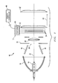
- FIG 5 illustrates again the housing assembly 10 of an exemplary embodiment of the present invention.
- the housing assembly is positioned to project a light beam towards a target (not shown) thereby to illuminate the target.
- the elements of the housing shown previously in the exploded view of Figure 1, are housed within a housing 78.
- the lens 44 through which the light beam is projected extends to a surface of the housing.
- the positioners 38 (shown in Figures 1 and 4) are all housed within the housing section 82 to position the dichroic filter supported therefrom at the same side of the light beam. Actuation of the translating actuators of the positioners cause the respective filters selectably to be positioned in the path of the light beam within the housing of the light assembly.
- Figure 6 illustrates a method flow diagram, shown generally at 86, representative of the method of operation of an embodiment of the present invention.
- the method facilitates formation of a light beam that exhibits selected color characteristics.
- selection is made of the color that the light beam is to exhibit.
- selectably position each dichroic filter in a selected position relative to the light beam generated by the housing assembly.
- the light beam is projected through the dichroic filters that filter the light beam and form a resultant, filtered light beam of desired color characteristics.
- dichroic filters Because the color characteristics of the light beam generated by the lighting assembly is easily changeable, merely by translating the dichroic filters to position a desired combination of filter portions in the path of the light beam, successive changes of light colors are readily implemented.
- the use of dichroic filters also advantageously increases the longevity of the lighting assembly as the dichroic filters are relatively unsusceptible to damage caused by heat.
- One or more dichroic filters are selectably positioned in the path of a light beam generated by a light source.
- a positioner supportively positions the dichroic filter and effectuates its translation into and out of the path of the light beam.
- a set of dichroic filters, each separately supported by a separate actuating positioner permits a combination of dichroic filters to be combined to cause the light color of the light beam to be of any desired color.
Landscapes
- Engineering & Computer Science (AREA)
- General Engineering & Computer Science (AREA)
- Physics & Mathematics (AREA)
- Spectroscopy & Molecular Physics (AREA)
- Non-Portable Lighting Devices Or Systems Thereof (AREA)
- Mechanical Light Control Or Optical Switches (AREA)
Applications Claiming Priority (2)
| Application Number | Priority Date | Filing Date | Title |
|---|---|---|---|
| US48884803P | 2003-07-21 | 2003-07-21 | |
| US488848P | 2003-07-21 |
Publications (2)
| Publication Number | Publication Date |
|---|---|
| EP1505337A2 true EP1505337A2 (fr) | 2005-02-09 |
| EP1505337A3 EP1505337A3 (fr) | 2008-10-01 |
Family
ID=33552103
Family Applications (1)
| Application Number | Title | Priority Date | Filing Date |
|---|---|---|---|
| EP04017006A Withdrawn EP1505337A3 (fr) | 2003-07-21 | 2004-07-19 | Appareil de changement de couleur et méthode correspondant pour dispositif d'éclairage |
Country Status (2)
| Country | Link |
|---|---|
| US (1) | US7163317B2 (fr) |
| EP (1) | EP1505337A3 (fr) |
Cited By (1)
| Publication number | Priority date | Publication date | Assignee | Title |
|---|---|---|---|---|
| GB2438921A (en) * | 2006-06-02 | 2007-12-12 | Hilclare Ltd | Light fitting |
Families Citing this family (15)
| Publication number | Priority date | Publication date | Assignee | Title |
|---|---|---|---|---|
| JP2005326777A (ja) * | 2004-05-17 | 2005-11-24 | Fujinon Corp | レンズ鏡胴 |
| DE602006006026D1 (de) * | 2005-02-04 | 2009-05-14 | Whiterock Design Llc | Optisches system für ein washlight |
| US7600891B2 (en) * | 2006-09-07 | 2009-10-13 | Belliveau Richard S | Theatre light apparatus incorporating LED tracking system |
| US7832902B2 (en) * | 2007-06-20 | 2010-11-16 | Barco Lighting Systems, Inc. | Heat resistant color mixing flag for a multiparameter light |
| US20090196044A1 (en) * | 2008-01-23 | 2009-08-06 | Omnicolor, L.P. | Method and apparatus for bidirectional control of the color and diffusion of a light beam |
| US8113691B2 (en) * | 2008-03-11 | 2012-02-14 | Robe Lighting S.R.O. | Color change mechanism |
| DK177579B1 (en) * | 2010-04-23 | 2013-10-28 | Martin Professional As | Led light fixture with background lighting |
| FR2988808B1 (fr) | 2012-03-27 | 2014-03-21 | Maquet Sas | Dispositif d'eclairage a led blanche, appareil d'eclairage |
| CN102818221B (zh) * | 2012-09-13 | 2015-11-25 | 广州市浩洋电子有限公司 | 一种用于舞台灯具的光学系统 |
| WO2014119277A1 (fr) * | 2013-01-30 | 2014-08-07 | キヤノン電子株式会社 | Dispositif de réglage de la quantité de lumière et dispositif optique |
| US10880963B2 (en) * | 2017-06-20 | 2020-12-29 | Harman Professional Denmark Aps | Method of providing color temperature correction of a light beam using a color filter system |
| CN107842815B (zh) * | 2017-10-19 | 2023-12-01 | 广州市浩洋电子股份有限公司 | 一种舞台灯色温补偿系统及方法 |
| US20190219249A1 (en) * | 2019-03-28 | 2019-07-18 | Robe Lighting S.R.O. | LED Light Engine with Integrated Color System |
| US10845030B1 (en) | 2020-02-26 | 2020-11-24 | Electronic Theatre Controls, Inc. | Lighting fixture with internal shutter blade |
| CN118295190A (zh) * | 2023-01-03 | 2024-07-05 | 中强光电股份有限公司 | 光调节模块 |
Citations (1)
| Publication number | Priority date | Publication date | Assignee | Title |
|---|---|---|---|---|
| US6142652A (en) | 1998-06-15 | 2000-11-07 | Richardson; Brian Edward | Color filter module for projected light |
Family Cites Families (19)
| Publication number | Priority date | Publication date | Assignee | Title |
|---|---|---|---|---|
| US3260152A (en) * | 1962-03-26 | 1966-07-12 | Pavelle Corp | Color printing apparatus |
| FR2503396A1 (fr) * | 1981-04-03 | 1982-10-08 | Kis France Sa | Filtre soustractif pour le tirage de film photographique en couleurs |
| US4894760A (en) * | 1982-11-19 | 1990-01-16 | Michael Callahan | Additive color-mixing light fixture employing a single moveable multi-filter array |
| US4958265A (en) * | 1988-03-04 | 1990-09-18 | Altman Stage Lighting Co., Inc. | Symmetrical color changer system |
| US4914556A (en) * | 1988-07-26 | 1990-04-03 | Morpheus Lights, Inc. | Spectral filter module |
| US4984143A (en) * | 1988-07-26 | 1991-01-08 | Morpheus Lights, Inc. | Color filter changer |
| US5126886A (en) * | 1989-04-10 | 1992-06-30 | Morpheus Lights, Inc. | Scrolling primary color changer |
| US5188452A (en) * | 1991-09-27 | 1993-02-23 | Altman Stage Lighting Co., Inc. | Color mixing lighting assembly |
| US5515254A (en) * | 1995-03-07 | 1996-05-07 | High End Systems, Inc. | Automated color mixing wash luminaire |
| US6466372B1 (en) * | 1997-05-16 | 2002-10-15 | G. Michael Morris | Systems for projecting images from diffractive phase plates |
| US5825548A (en) * | 1997-09-11 | 1998-10-20 | Vari-Lite, Inc. | Cross-fading color filter and system |
| US5969868A (en) * | 1997-09-11 | 1999-10-19 | Vari-Lite, Inc. | Sequential cross-fading color filters and system |
| EP1234197B1 (fr) * | 1999-11-18 | 2004-03-24 | Martin Professional A/S | Systeme optique permettant de creer des zones de lumiere coloree et ses composants |
| US6379025B1 (en) * | 2000-03-31 | 2002-04-30 | Pacfab, Inc. | Submersible lighting fixture with color wheel |
| US6578987B1 (en) * | 2000-05-03 | 2003-06-17 | Vari-Lite, Inc. | Intra-lens color and dimming apparatus |
| DE10048988C1 (de) * | 2000-09-27 | 2002-02-28 | Feddersen Clausen Oliver | Subtraktives Farbmischsystem für Beleuchtung mit in der Farbsättigung abgestuften Farbmischelementen |
| US6502961B1 (en) * | 2000-11-20 | 2003-01-07 | Brian Edward Richardson | Conical lens array to control projected light beam color, divergence, and shape |
| US6796683B2 (en) * | 2003-05-09 | 2004-09-28 | High End Systems, Inc. | Color mixing apparatus for theatrical ellipsoidal spotlights |
| US6974232B1 (en) * | 2003-10-14 | 2005-12-13 | Brian Edward Richardson | Compact lighting system with improved light transmission and color filters |
-
2004
- 2004-03-19 US US10/804,572 patent/US7163317B2/en not_active Expired - Fee Related
- 2004-07-19 EP EP04017006A patent/EP1505337A3/fr not_active Withdrawn
Patent Citations (1)
| Publication number | Priority date | Publication date | Assignee | Title |
|---|---|---|---|---|
| US6142652A (en) | 1998-06-15 | 2000-11-07 | Richardson; Brian Edward | Color filter module for projected light |
Cited By (1)
| Publication number | Priority date | Publication date | Assignee | Title |
|---|---|---|---|---|
| GB2438921A (en) * | 2006-06-02 | 2007-12-12 | Hilclare Ltd | Light fitting |
Also Published As
| Publication number | Publication date |
|---|---|
| EP1505337A3 (fr) | 2008-10-01 |
| US7163317B2 (en) | 2007-01-16 |
| US20050018423A1 (en) | 2005-01-27 |
Similar Documents
| Publication | Publication Date | Title |
|---|---|---|
| EP1505337A2 (fr) | Appareil de changement de couleur et méthode correspondant pour dispositif d'éclairage | |
| EP0192882B1 (fr) | Source lumineuse avec variation automatique de la couleur, de la saturation et de la divergence du faisceau | |
| US6578987B1 (en) | Intra-lens color and dimming apparatus | |
| US4298920A (en) | Automatic gel changer for a spotlight | |
| KR940001584B1 (ko) | 가변색상 조명장치 | |
| US5186536A (en) | Lighting instrument with movable filters and associated actuation mechanism | |
| EP2920507B1 (fr) | Luminaire muni d'un homogénéisateur de faisceau lumineux allongé articulé | |
| US6513954B2 (en) | Rainbow projection light | |
| EP2885576A1 (fr) | Système de diffusion amélioré pour un luminaire automatique | |
| US20110103074A1 (en) | Diffusion system for and automated luminaire | |
| US20060268558A1 (en) | Method and apparatus for controlling diffusion and color of a light beam | |
| EP2550673B1 (fr) | Luminaire automatisé à source de lumière à plasma | |
| US12066172B2 (en) | Stage light fixture having light effect elements server | |
| US7896525B2 (en) | Heat resistant color mixing flag for a multiparameter light | |
| US6520662B1 (en) | Projector particularly for projecting light in infinite colors, with high-power beam | |
| JPH09204810A (ja) | 照明装置 |
Legal Events
| Date | Code | Title | Description |
|---|---|---|---|
| PUAI | Public reference made under article 153(3) epc to a published international application that has entered the european phase |
Free format text: ORIGINAL CODE: 0009012 |
|
| 17P | Request for examination filed |
Effective date: 20040719 |
|
| AK | Designated contracting states |
Kind code of ref document: A2 Designated state(s): AT BE BG CH CY CZ DE DK EE ES FI FR GB GR HU IE IT LI LU MC NL PL PT RO SE SI SK TR |
|
| AX | Request for extension of the european patent |
Extension state: AL HR LT LV MK |
|
| PUAL | Search report despatched |
Free format text: ORIGINAL CODE: 0009013 |
|
| AK | Designated contracting states |
Kind code of ref document: A3 Designated state(s): AT BE BG CH CY CZ DE DK EE ES FI FR GB GR HU IE IT LI LU MC NL PL PT RO SE SI SK TR |
|
| AX | Request for extension of the european patent |
Extension state: AL HR LT LV MK |
|
| 17Q | First examination report despatched |
Effective date: 20090225 |
|
| AKX | Designation fees paid |
Designated state(s): DE FR GB IT NL |
|
| STAA | Information on the status of an ep patent application or granted ep patent |
Free format text: STATUS: THE APPLICATION IS DEEMED TO BE WITHDRAWN |
|
| 18D | Application deemed to be withdrawn |
Effective date: 20101007 |