EP1505361A2 - Appareil d'échange de chaleur et son procédé de fabrication - Google Patents
Appareil d'échange de chaleur et son procédé de fabrication Download PDFInfo
- Publication number
- EP1505361A2 EP1505361A2 EP04018175A EP04018175A EP1505361A2 EP 1505361 A2 EP1505361 A2 EP 1505361A2 EP 04018175 A EP04018175 A EP 04018175A EP 04018175 A EP04018175 A EP 04018175A EP 1505361 A2 EP1505361 A2 EP 1505361A2
- Authority
- EP
- European Patent Office
- Prior art keywords
- refrigerant
- particular according
- lid
- degrees
- devices
- Prior art date
- Legal status (The legal status is an assumption and is not a legal conclusion. Google has not performed a legal analysis and makes no representation as to the accuracy of the status listed.)
- Withdrawn
Links
- 238000004519 manufacturing process Methods 0.000 title claims abstract description 11
- 238000000034 method Methods 0.000 title claims description 7
- 239000007788 liquid Substances 0.000 claims abstract description 6
- 239000003507 refrigerant Substances 0.000 claims description 106
- 238000003466 welding Methods 0.000 claims description 3
- 238000005476 soldering Methods 0.000 claims description 2
- 150000001875 compounds Chemical class 0.000 claims 2
- 238000009795 derivation Methods 0.000 claims 1
- 238000009826 distribution Methods 0.000 abstract description 32
- 239000002826 coolant Substances 0.000 abstract 2
- 238000000926 separation method Methods 0.000 description 7
- 238000004080 punching Methods 0.000 description 2
- 239000003990 capacitor Substances 0.000 description 1
- 238000011161 development Methods 0.000 description 1
- 230000018109 developmental process Effects 0.000 description 1
- 238000005516 engineering process Methods 0.000 description 1
- 239000002689 soil Substances 0.000 description 1
Images

Classifications
-
- F—MECHANICAL ENGINEERING; LIGHTING; HEATING; WEAPONS; BLASTING
- F28—HEAT EXCHANGE IN GENERAL
- F28F—DETAILS OF HEAT-EXCHANGE AND HEAT-TRANSFER APPARATUS, OF GENERAL APPLICATION
- F28F9/00—Casings; Header boxes; Auxiliary supports for elements; Auxiliary members within casings
- F28F9/02—Header boxes; End plates
- F28F9/0219—Arrangements for sealing end plates into casing or header box; Header box sub-elements
- F28F9/0224—Header boxes formed by sealing end plates into covers
-
- F—MECHANICAL ENGINEERING; LIGHTING; HEATING; WEAPONS; BLASTING
- F28—HEAT EXCHANGE IN GENERAL
- F28D—HEAT-EXCHANGE APPARATUS, NOT PROVIDED FOR IN ANOTHER SUBCLASS, IN WHICH THE HEAT-EXCHANGE MEDIA DO NOT COME INTO DIRECT CONTACT
- F28D1/00—Heat-exchange apparatus having stationary conduit assemblies for one heat-exchange medium only, the media being in contact with different sides of the conduit wall, in which the other heat-exchange medium is a large body of fluid, e.g. domestic or motor car radiators
- F28D1/02—Heat-exchange apparatus having stationary conduit assemblies for one heat-exchange medium only, the media being in contact with different sides of the conduit wall, in which the other heat-exchange medium is a large body of fluid, e.g. domestic or motor car radiators with heat-exchange conduits immersed in the body of fluid
- F28D1/04—Heat-exchange apparatus having stationary conduit assemblies for one heat-exchange medium only, the media being in contact with different sides of the conduit wall, in which the other heat-exchange medium is a large body of fluid, e.g. domestic or motor car radiators with heat-exchange conduits immersed in the body of fluid with tubular conduits
- F28D1/053—Heat-exchange apparatus having stationary conduit assemblies for one heat-exchange medium only, the media being in contact with different sides of the conduit wall, in which the other heat-exchange medium is a large body of fluid, e.g. domestic or motor car radiators with heat-exchange conduits immersed in the body of fluid with tubular conduits the conduits being straight
- F28D1/0535—Heat-exchange apparatus having stationary conduit assemblies for one heat-exchange medium only, the media being in contact with different sides of the conduit wall, in which the other heat-exchange medium is a large body of fluid, e.g. domestic or motor car radiators with heat-exchange conduits immersed in the body of fluid with tubular conduits the conduits being straight the conduits having a non-circular cross-section
- F28D1/05366—Assemblies of conduits connected to common headers, e.g. core type radiators
- F28D1/05391—Assemblies of conduits connected to common headers, e.g. core type radiators with multiple rows of conduits or with multi-channel conduits combined with a particular flow pattern, e.g. multi-row multi-stage radiators
-
- F—MECHANICAL ENGINEERING; LIGHTING; HEATING; WEAPONS; BLASTING
- F28—HEAT EXCHANGE IN GENERAL
- F28F—DETAILS OF HEAT-EXCHANGE AND HEAT-TRANSFER APPARATUS, OF GENERAL APPLICATION
- F28F9/00—Casings; Header boxes; Auxiliary supports for elements; Auxiliary members within casings
- F28F9/02—Header boxes; End plates
- F28F9/0202—Header boxes having their inner space divided by partitions
- F28F9/0204—Header boxes having their inner space divided by partitions for elongated header box, e.g. with transversal and longitudinal partitions
- F28F9/0207—Header boxes having their inner space divided by partitions for elongated header box, e.g. with transversal and longitudinal partitions the longitudinal or transversal partitions being separate elements attached to header boxes
-
- F—MECHANICAL ENGINEERING; LIGHTING; HEATING; WEAPONS; BLASTING
- F28—HEAT EXCHANGE IN GENERAL
- F28F—DETAILS OF HEAT-EXCHANGE AND HEAT-TRANSFER APPARATUS, OF GENERAL APPLICATION
- F28F9/00—Casings; Header boxes; Auxiliary supports for elements; Auxiliary members within casings
- F28F9/02—Header boxes; End plates
- F28F9/0219—Arrangements for sealing end plates into casing or header box; Header box sub-elements
- F28F9/0221—Header boxes or end plates formed by stacked elements
-
- F—MECHANICAL ENGINEERING; LIGHTING; HEATING; WEAPONS; BLASTING
- F28—HEAT EXCHANGE IN GENERAL
- F28F—DETAILS OF HEAT-EXCHANGE AND HEAT-TRANSFER APPARATUS, OF GENERAL APPLICATION
- F28F9/00—Casings; Header boxes; Auxiliary supports for elements; Auxiliary members within casings
- F28F9/02—Header boxes; End plates
- F28F9/026—Header boxes; End plates with static flow control means, e.g. with means for uniformly distributing heat exchange media into conduits
-
- F—MECHANICAL ENGINEERING; LIGHTING; HEATING; WEAPONS; BLASTING
- F28—HEAT EXCHANGE IN GENERAL
- F28F—DETAILS OF HEAT-EXCHANGE AND HEAT-TRANSFER APPARATUS, OF GENERAL APPLICATION
- F28F9/00—Casings; Header boxes; Auxiliary supports for elements; Auxiliary members within casings
- F28F9/26—Arrangements for connecting different sections of heat-exchange elements, e.g. of radiators
- F28F9/262—Arrangements for connecting different sections of heat-exchange elements, e.g. of radiators for radiators
-
- F—MECHANICAL ENGINEERING; LIGHTING; HEATING; WEAPONS; BLASTING
- F28—HEAT EXCHANGE IN GENERAL
- F28D—HEAT-EXCHANGE APPARATUS, NOT PROVIDED FOR IN ANOTHER SUBCLASS, IN WHICH THE HEAT-EXCHANGE MEDIA DO NOT COME INTO DIRECT CONTACT
- F28D21/00—Heat-exchange apparatus not covered by any of the groups F28D1/00 - F28D20/00
- F28D2021/0019—Other heat exchangers for particular applications; Heat exchange systems not otherwise provided for
- F28D2021/0068—Other heat exchangers for particular applications; Heat exchange systems not otherwise provided for for refrigerant cycles
- F28D2021/0073—Gas coolers
Definitions
- the present invention relates to an apparatus for replacement of heat, in particular for a motor vehicle, and a method for the same Production.
- Such devices for the exchange of heat are from the prior Technics known, such as capacitors for gas cooler and the like.
- These devices have a variety of flow devices, such as For example, flat tubes, through which a liquid or gaseous Medium, in particular - but not exclusively - a refrigerant flows.
- a liquid or gaseous Medium in particular - but not exclusively - a refrigerant flows.
- At the ends of the flat tubes are collecting and / or distribution facilities provided which the refrigerant either on the individual Distribute flat tubes or the refrigerant leaving the flat tubes collect.
- the invention is therefore based on the object, the cost of production to reduce a device for the exchange of heat. Besides should the assembly costs be reduced during manufacture and a greater freedom in the wiring choice of the device for replacement be ensured by heat.
- the invention relates to a device for exchanging heat, in particular for a motor vehicle, with at least one heat exchanger assembly, this at least one heat exchanger assembly at least a supply for a liquid and / or gaseous medium, at least a collection and / or distribution device, a plurality of Flow-through devices and at least one derivative for the medium.
- the at least one collecting and / or distribution device at least one bottom device, at least one refrigerant guide device and at least one lid device, wherein the Refrigerant guide device between the bottom device and the Dekkel wisdom is provided.
- the bottom device, the refrigerant guiding device and the lid device are designed as a modular unit.
- the collection and / or distribution facilities serve to liquid and / or gaseous medium either to the plurality of flow devices to distribute or the emerging from the flow devices To collect medium.
- a refrigerant guiding device is understood to mean a device which the refrigerant, that is the liquid and / or gaseous medium, leads to a substantially predetermined flow path.
- the refrigerant guiding device between the ground device and the lid device is understood to mean that the refrigerant guiding device sandwiched between the lid device and the bottom device lies.
- At least the bottom device and / or the refrigerant guiding device and / or the lid device a substantially plate-like shape.
- the device substantially in two to each other extends perpendicular directions and in contrast in a third Direction only a relatively small extent.
- plate-shaped structures are also understood to mean those which are in one to the first two mentioned vertical directions vaults, Have projections and the like.
- a plate-shaped is further considered if the facilities concerned Have recesses.
- an im essential rectangular hollow body conceived as a plate-shaped.
- the cross-section of the plate-shaped body does not necessarily have to may be rectangular, but may also have deviating cross sections.
- At least one refrigerant guiding device at least one recess.
- At least one refrigerant guiding device has a plurality of recesses on, wherein at least a portion of at least one recess substantially along a longitudinal direction of the refrigerant guiding means extends.
- At least two recesses essentially separated from each other gas- and / or liquid-tight. This means that the geometric areas of the recesses do not intersect and / or touch in any area.
- At least one refrigerant guiding device at least one refrigerant guide section on, which is at a predetermined angle to the longitudinal direction the refrigerant guide means extends.
- This predetermined angle of the at least one refrigerant guide section with respect to the longitudinal direction of the refrigerant guiding device lies between 0 ° and 90 °, preferably between 30 ° and 90 ° and especially preferably between 60 ° and 90 °. However, they are also larger angles conceivable as 90 °.
- a plurality of flow devices provided, wherein a proportion of the flow devices substantially arranged in a first level and another share in a second plane substantially parallel to this first plane.
- the Refrigerant guide section serves to the refrigerant from flow devices one level in flow-through facilities of the other level convert.
- the individual recesses which serve as flow channels for the refrigerant serve, can be uniform, that is under predetermined symmetries, be distributed over the refrigerant guide device or unevenly.
- several recesses, in particular also different geometric shape, in the depth of the refrigerant guide device be arranged or the cross section of the recess may be with Change the depth of the refrigerant guide device.
- At least one refrigerant guiding device at least one gas and / or liquid-tight completed end section on.
- at least one end section at least one refrigerant guide device designed in such a way is that substantially no recess extends in this end portion. Preference is given to all end sections of all the refrigerant guiding devices Completed gas and / or liquid-tight.
- At least the bottom device and / or the lid device at least one arched Section on.
- Under a curved section is understood a section, located in a to a level of the floor and / or cover device extends in the vertical direction.
- the vaulting can be arbitrary have geometric shapes, such as circular or general curved cross sections, rectangular, edgy, polygonal and like.
- the ground and the Cover device in each case two curved sections, wherein the respective two curved portions substantially along the longitudinal direction extend the bottom and / or lid means.
- the curved sections lie the bottom and / or the lid device at least partially below and / or above that provided in the refrigerant guide means Cutouts. This means that when the ground facility, the Refrigerant guide device and the lid device stacked be in the area in which the refrigerant guide means a recess also has a curvature in the bottom and / or lid device is provided.
- the individual vaults one have constant shape and / or size, but they can also in terms of their shape and / or size.
- the bottom and / or the lid means have curved portions. In addition, only the bottom device or the lid device Have bulges to a predetermined hydraulic Diameter to produce.
- At least the bottom device and / or the refrigerant guiding device and / or the Cover device at least one hole.
- the bottom device, the refrigerant guiding device and the Dekkel Schweikkel
- Holes which are arranged so that an im essentially elongated body through all three holes simultaneously can be passed. These holes serve the three bodies to hold each other in a predetermined position to this vorzufix Schl.
- recesses may be provided, in which Protrusions of each other's intervention to intervene on this Way to achieve a spatial prefixing.
- the heat exchanger assembly may be a collection and / or distribution device or several collection and / or distribution facilities exhibit.
- flow devices can be provided be, which with both end sections in a collection and / or Distribution device open.
- the bottom device a plurality of receiving means for the plurality of flow devices on.
- These recording devices can be any contour own and for example as passages for the flow devices be equipped.
- the receiving devices a substantially elongated shape. Under elongated is understood that the receiving devices themselves extend substantially in one direction and in contrast only slightly in another direction perpendicular to this direction.
- the receiving devices at a predetermined angle to the longitudinal direction of the Ground facility arranged.
- Angle is understood to mean the angle, opposite to the main expansion direction of the receiving device the longitudinal direction of the ground device occupies. This angle is between 0 ° and 90 °, preferably between 0 ° and 45 ° and especially preferably between 0 ° and 10 °.
- the receiving devices Auxiliary devices which as an introduction aids for Flow devices serve. This may be, for example, additional Deformations, such as chamfers, act.
- At least one bottom device at least one recess, preferably in the Longitudinal device of the bottom device is arranged.
- the recess preferably provided such that it is between two groups of Recording facilities is located.
- the two groups of reception facilities assigned to the two parts of the flow devices, which lie in different levels. The arrangement of the recess will be further discussed with reference to the figures.
- the flow-through devices a substantially flat tube-like cross section.
- the flow-through a Have cross section wherein the longer side of this cross section, the shorter By far surpasses page, such as a rectangle, which has a much longer longitudinal side than broadside.
- other cross sections for the flow devices provided such as rectangular, polygonal, elliptical and hybrids it.
- the flow-through devices an end portion, opposite to the other flow devices twisted and / or twisted.
- This twist can be Angle between 0 ° and 90 °, preferably between 45 ° and 90 ° and especially preferably between 80 ° and 90 ° occupy.
- a portion of the flow device is in one first level and a second portion of the flow device in a second, to this first plane parallel surface.
- the flow devices can also be designed so that they have a curved or Curved portion, so as not to be between two collection and / or To extend distribution devices, but that an end portion the flow-through of a section of a single collection and / or distribution means emanates, and a second end portion the same flow devices in another section of the collection and / or Distribution device opens.
- the rotation or twisting of the individual flow devices can at the same time as a pipe stop of the end portion in the collection and / or Distribution device serve.
- the device for exchanging heat may be from top to bottom or bottom to bottom of the refrigerant flows through the top.
- the individual collection and / or distribution facilities can be geometric above and below with respect to the device or laterally with respect to lie the device.
- a plurality of refrigerant guiding means is provided, which between the bottom device and the lid device are provided.
- These individual refrigerant guide devices can be different Recesses, that is recesses with different geometric cross section, have.
- the bottom device and / or the at least one refrigerant guiding device and / or the Cover means a connection on, which consists of a group of connections is selected, which riveting, soldering, welding and the like contains.
- the invention is further directed to a method of manufacturing a device directed to the exchange of heat of the kind mentioned above. It will be in a first method step, a bottom device of the above-designated Manufactured type, further at least one refrigerant guiding device of above-mentioned type, and a lid device of the above Art.
- refrigerant guide means are preferably recesses, for example, by punching introduced. Further, preferred introduced into the bottom and / or lid means buckles.
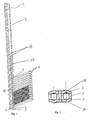
- reference numeral 1 denotes a collecting and / or distributing means in their entirety.
- the reference numeral 4 denotes a cover device, the reference numeral 3 the refrigerant guiding device, wherein the recesses are not shown here, and the reference numeral 2 the ground facility.
- the reference numeral 6 denotes a plurality of flat tube-like Flow devices.
- the flow devices can be inside Have one or more flow channels for the refrigerant.
- the Reference numeral 7 denotes an end portion of the flow device, which is opposite to the flow device (here by 90 °) twisted.
- the reference numeral 5 denotes a receiving device in which a flow device 6 can be inserted.
- the reference number 19 indicates holes, which for pre-fixing the Bodenund / or the refrigerant guiding and / or the lid device used becomes.
- the reference numerals 17 and 18 indicate in the ground device 2 provided punches, which promote the thermal separation serve the individual flow areas.
- FIG. 2 shows a cross section of the collecting and distributing device 1.
- Reference numerals 2, 3 and 4 again refer to a ground facility, a refrigerant guiding device and a lid device.
- both the bottom device and the lid device 4 Have vaults 16. These vaults are provided in the area in which also the recesses of the refrigerant guiding device 3 are provided and serve to increase the refrigerant flow cross-section and / or, if necessary, also for improving the printing technology Properties.
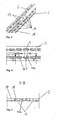
- FIG. 3 shows a detail of a ground device according to the invention.
- the reference numeral 5 indicates the receiving device for the flow devices.
- the reference numeral 16 refers to buckles, the are merely indicated here.
- the reference numeral 19 denotes two Holes, which serve for prefixing.
- Reference numeral 18 denotes a recess or a punched out area, which promotes the thermal separation is used.
- Fig. 4 shows a detailed view of the bottom device of Fig. 3 in one Top view.
- the reference numeral 16a denotes a curvature, the from the receiving device 5 to the receiving device 5 'ranges.
- this Area preferably has the belonging to this bottom device refrigerant guide device a recess that runs parallel to this camber 16 runs.
- Fig. 5 shows a side view along the lines B-B of Fig. 4.
- the reference numeral 19 denotes a bore
- the reference numeral 18 the recess for thermal separation
- the reference numeral 16 or 16a the vaults.
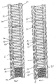
- Fig. 6 shows a refrigerant guiding device according to the invention in one first embodiment.
- the refrigerant guiding device four recesses 8, 9, 10 and 11 on.
- the recess 9 connected to the recess 10 via a portion 12.
- This Section facing the longitudinal direction L of the refrigerant guiding device an angle of 90 °.
- the angle can also be 90 ° differ.
- Reference numerals 17 and 18 relate to recesses or cutouts, which serve the thermal separation. Such cutouts can also be in the upper area, that is in the area that is parallel to the recess 11, be provided. A special meaning However, comes in the punching that serve the thermal separation in the area in which the refrigerant enters the device, since here the Temperature gradient of the refrigerant during the flow particularly are high.
- Reference numeral 19 denotes a bore and the reference numerals 13 and 14 indicate wall portions of the refrigerant guide device, through which the individual recesses are separated.
- the Reference numerals 15 refer to end sections or wall sections, through which the refrigerant guide device up and down is closed.
- FIG. 7 shows that assigned to the refrigerant guiding device shown in FIG. 6 Cover device 4.
- the reference numerals 16 refer to Vaults, which have corresponding recesses 8, 9, 10 and 11 of the Refrigerant guide device are mounted. Also in the lid device 18 are a recess or cutout for thermal separation and holes 19 are provided. Reference numeral 16 refers to the provided vaults.
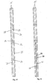
- the refrigerant guide is within the device for replacement represented by heat.
- the lid devices were illustrative omitted.
- the refrigerant first enters the region 20 the refrigerant guiding device. Within this range it can spread along its entire length and then passes through this Area associated flow means 6 in the lower Sammelund Distribution device 21 a. In this area, the refrigerant can essentially along the entire length of the collection and Distribute distribution device and passes through the flat tubes 6 in the Area 22 of the collection and / or distribution facility 1. From here the refrigerant passes through the section 12 in the region 23, which is limited by the wall sections 14 and 15.
- the refrigerant returns in the collecting and / or distribution device 21, where it again about whose entire length can spread, and finally passes through the Flat tubes 6 in the region 24 of the collection and / or distribution device 1. From here, the refrigerant flows through a drain (not shown) from the device.
- FIG. 8 shows a further possibility of the refrigerant guide within the Apparatus for exchanging heat, which is characterized by the (not shown) Design of the collection and distribution device 21 differs, as will be explained with reference to FIGS. 10 and 11. there the refrigerant passes from the region 20 via the flow devices 6 in the collecting and / or distribution device 21.
- FIG. 9 here extends the (not shown) Not recess along the entire length of the collection and Distribution device 21, but corresponds in length substantially the length of the recess 20.
- the refrigerant therefore passes through a (not shown) connecting portion in the lower collecting and distributing device and via the flow devices 6 in the area 23rd the collection and distribution device 1 and from there via the connection area 12 in the area 22 of the collection and distribution facility 1. From there, the refrigerant returns via the flow devices in the collection and distribution device 21 and finally again on the Flow-through devices 6 in the area 24, from where it leaves the device flows.
- Figures 10 and 11 show refrigerant guiding means of the collecting and Distribution devices 21, wherein the refrigerant guiding device in Fig. 10 is associated with the device of Fig. 8 and the refrigerant guiding means from FIG. 11 of the device from FIG. 9.
- the refrigerant guide device shown in Fig. 10 has four recesses 25, 26, 27 and 28.
- the recesses 25 and 27 are over a section 29 fluidly connected to each other and also the sections 26 and 28 via a section 29.
- the reference numerals 14 and 13 mark wall portions which the recesses 27 and the recesses 25 and 26 from each other gas and / or liquid-tight split off.
- FIG. 11 shows a refrigerant guiding device in a further embodiment, here only two recesses are provided, which essentially along the longitudinal direction of the refrigerant guiding device extend and which of each other gas and / or liquid-tight are separated.
- recesses 17 and 18 for thermal Separation provided. In this case, there is no connection between the recesses, that is no overflow or the like provided.
Landscapes
- Engineering & Computer Science (AREA)
- Physics & Mathematics (AREA)
- Thermal Sciences (AREA)
- Mechanical Engineering (AREA)
- General Engineering & Computer Science (AREA)
- Heat-Exchange Devices With Radiators And Conduit Assemblies (AREA)
- Cooling Or The Like Of Semiconductors Or Solid State Devices (AREA)
- Cooling Or The Like Of Electrical Apparatus (AREA)
Applications Claiming Priority (2)
| Application Number | Priority Date | Filing Date | Title |
|---|---|---|---|
| DE10336625 | 2003-08-05 | ||
| DE2003136625 DE10336625A1 (de) | 2003-08-05 | 2003-08-05 | Vorrichtung zum Austausch von Wärme und Verfahren zu deren Herstellung |
Publications (2)
| Publication Number | Publication Date |
|---|---|
| EP1505361A2 true EP1505361A2 (fr) | 2005-02-09 |
| EP1505361A3 EP1505361A3 (fr) | 2007-11-21 |
Family
ID=33547173
Family Applications (1)
| Application Number | Title | Priority Date | Filing Date |
|---|---|---|---|
| EP04018175A Withdrawn EP1505361A3 (fr) | 2003-08-05 | 2004-07-30 | Appareil d'échange de chaleur et son procédé de fabrication |
Country Status (2)
| Country | Link |
|---|---|
| EP (1) | EP1505361A3 (fr) |
| DE (1) | DE10336625A1 (fr) |
Family Cites Families (10)
| Publication number | Priority date | Publication date | Assignee | Title |
|---|---|---|---|---|
| JP2801373B2 (ja) * | 1990-07-02 | 1998-09-21 | サンデン株式会社 | 熱交換器 |
| US5241839A (en) * | 1991-04-24 | 1993-09-07 | Modine Manufacturing Company | Evaporator for a refrigerant |
| US5205347A (en) * | 1992-03-31 | 1993-04-27 | Modine Manufacturing Co. | High efficiency evaporator |
| DE19649129A1 (de) * | 1996-11-27 | 1998-05-28 | Behr Gmbh & Co | Flachrohr-Wärmeübertrager mit umgeformtem Flachrohrendabschnitt |
| JPH11226685A (ja) * | 1998-02-16 | 1999-08-24 | Denso Corp | 熱交換器およびヘッダタンクの製造方法 |
| FR2793016B1 (fr) * | 1999-04-30 | 2001-09-07 | Valeo Climatisation | Boite collectrice allongee pour echangeur de chaleur resistant aux fortes pressions internes |
| JP4026277B2 (ja) * | 1999-05-25 | 2007-12-26 | 株式会社デンソー | 熱交換器 |
| US6745827B2 (en) * | 2001-09-29 | 2004-06-08 | Halla Climate Control Corporation | Heat exchanger |
| JP2005513403A (ja) * | 2001-12-21 | 2005-05-12 | ベール ゲーエムベーハー ウント コー カーゲー | 特に自動車用の熱交換器 |
| DE10202768A1 (de) * | 2002-01-25 | 2003-07-31 | Behr Gmbh & Co | Wärmeübertrager |
-
2003
- 2003-08-05 DE DE2003136625 patent/DE10336625A1/de not_active Ceased
-
2004
- 2004-07-30 EP EP04018175A patent/EP1505361A3/fr not_active Withdrawn
Also Published As
| Publication number | Publication date |
|---|---|
| DE10336625A1 (de) | 2005-03-10 |
| EP1505361A3 (fr) | 2007-11-21 |
Similar Documents
| Publication | Publication Date | Title |
|---|---|---|
| DE69306065T2 (de) | Wärmetauscher | |
| EP2575418B1 (fr) | Refroidisseur électronique et procédé destiné à la fabrication d'un refroidisseur électronique | |
| DE3908266A1 (de) | Waermeaustauscher und verfahren zur fluessigkeitsdichten befestigung einer bodenplatte an einem waermetauschernetz | |
| EP0714008A2 (fr) | Echangeur de chaleur avec boîte à eau | |
| EP3106823B1 (fr) | Échangeur de chaleur | |
| EP2859295A1 (fr) | Échangeur de chaleur | |
| DE10132617A1 (de) | Wärmeaustauscher | |
| DE69203388T2 (de) | Verfahren zur Herstellung eines Rohrbündelwärmetauschers. | |
| DE202019105238U1 (de) | Temperiermodul für eine Batterie, insbesondere Fahrzeugbatterie | |
| DE69406401T2 (de) | Wärmetauscher | |
| DE102020118216A1 (de) | Plattenartiger Fluidbehälter | |
| DE69311652T2 (de) | Wärmetauscher | |
| EP1759159A1 (fr) | Echangeur de chaleur | |
| DE202025105615U1 (de) | Batteriepack | |
| EP0674148B1 (fr) | Radiateur pour chauffer | |
| EP2167895A1 (fr) | Échangeur de chaleur | |
| EP1819458B1 (fr) | Procédé de production d'un échangeur de chaleur | |
| EP1505361A2 (fr) | Appareil d'échange de chaleur et son procédé de fabrication | |
| DE102018113339A1 (de) | Batteriekühlvorrichtung zur Kühlung einer Batterie, insbesondere der Batterie eines Kraftfahrzeugs bzw. Anordnungsstruktur mit mindestens einer Batterie, insbesondere einer Batterie eines Kraftfahrzeugs und mit der zuvor genannten Batteriekühlvorrichtung | |
| EP3239641A1 (fr) | Tube plat pour un caloporteur | |
| EP3077750B1 (fr) | Échangeur de chaleur avec canal collecteur pour l'extraction d'une phase liquide | |
| DE112015003901B4 (de) | Sammelkammer für einen Wärmetauscher, Verbindungssystem und Wärmetauscher | |
| EP1668304A1 (fr) | Unite d'echange thermique pour vehicules automobiles | |
| EP1011178A1 (fr) | Amplificateur laser de puissance, procédé de production et son utilisation | |
| DE102005058177A1 (de) | Verfahren zur Herstellung eines Wärmeaustauschers |
Legal Events
| Date | Code | Title | Description |
|---|---|---|---|
| PUAI | Public reference made under article 153(3) epc to a published international application that has entered the european phase |
Free format text: ORIGINAL CODE: 0009012 |
|
| AK | Designated contracting states |
Kind code of ref document: A2 Designated state(s): AT BE BG CH CY CZ DE DK EE ES FI FR GB GR HU IE IT LI LU MC NL PL PT RO SE SI SK TR |
|
| AX | Request for extension of the european patent |
Extension state: AL HR LT LV MK |
|
| PUAL | Search report despatched |
Free format text: ORIGINAL CODE: 0009013 |
|
| AK | Designated contracting states |
Kind code of ref document: A3 Designated state(s): AT BE BG CH CY CZ DE DK EE ES FI FR GB GR HU IE IT LI LU MC NL PL PT RO SE SI SK TR |
|
| AX | Request for extension of the european patent |
Extension state: AL HR LT LV MK |
|
| 17P | Request for examination filed |
Effective date: 20080521 |
|
| AKX | Designation fees paid |
Designated state(s): AT BE BG CH CY CZ DE DK EE ES FI FR GB GR HU IE IT LI LU MC NL PL PT RO SE SI SK TR |
|
| STAA | Information on the status of an ep patent application or granted ep patent |
Free format text: STATUS: THE APPLICATION IS DEEMED TO BE WITHDRAWN |
|
| 18D | Application deemed to be withdrawn |
Effective date: 20120201 |