EP1505376A1 - Formation d'image d'un objet avec détermination de phases d'un champ d'ondes de rayonnement - Google Patents
Formation d'image d'un objet avec détermination de phases d'un champ d'ondes de rayonnement Download PDFInfo
- Publication number
- EP1505376A1 EP1505376A1 EP04027179A EP04027179A EP1505376A1 EP 1505376 A1 EP1505376 A1 EP 1505376A1 EP 04027179 A EP04027179 A EP 04027179A EP 04027179 A EP04027179 A EP 04027179A EP 1505376 A1 EP1505376 A1 EP 1505376A1
- Authority
- EP
- European Patent Office
- Prior art keywords
- intensity
- representation
- integral transform
- produce
- measure
- Prior art date
- Legal status (The legal status is an assumption and is not a legal conclusion. Google has not performed a legal analysis and makes no representation as to the accuracy of the status listed.)
- Granted
Links
Images


Classifications
-
- G—PHYSICS
- G01—MEASURING; TESTING
- G01J—MEASUREMENT OF INTENSITY, VELOCITY, SPECTRAL CONTENT, POLARISATION, PHASE OR PULSE CHARACTERISTICS OF INFRARED, VISIBLE OR ULTRAVIOLET LIGHT; COLORIMETRY; RADIATION PYROMETRY
- G01J9/00—Measuring optical phase difference; Determining degree of coherence; Measuring optical wavelength
- G01J9/02—Measuring optical phase difference; Determining degree of coherence; Measuring optical wavelength by interferometric methods
-
- G—PHYSICS
- G01—MEASURING; TESTING
- G01B—MEASURING LENGTH, THICKNESS OR SIMILAR LINEAR DIMENSIONS; MEASURING ANGLES; MEASURING AREAS; MEASURING IRREGULARITIES OF SURFACES OR CONTOURS
- G01B9/00—Measuring instruments characterised by the use of optical techniques
- G01B9/02—Interferometers
- G01B9/02083—Interferometers characterised by particular signal processing and presentation
- G01B9/02084—Processing in the Fourier or frequency domain when not imaged in the frequency domain
-
- G—PHYSICS
- G01—MEASURING; TESTING
- G01B—MEASURING LENGTH, THICKNESS OR SIMILAR LINEAR DIMENSIONS; MEASURING ANGLES; MEASURING AREAS; MEASURING IRREGULARITIES OF SURFACES OR CONTOURS
- G01B9/00—Measuring instruments characterised by the use of optical techniques
- G01B9/02—Interferometers
- G01B9/02083—Interferometers characterised by particular signal processing and presentation
-
- G—PHYSICS
- G01—MEASURING; TESTING
- G01J—MEASUREMENT OF INTENSITY, VELOCITY, SPECTRAL CONTENT, POLARISATION, PHASE OR PULSE CHARACTERISTICS OF INFRARED, VISIBLE OR ULTRAVIOLET LIGHT; COLORIMETRY; RADIATION PYROMETRY
- G01J1/00—Photometry, e.g. photographic exposure meter
- G01J1/42—Photometry, e.g. photographic exposure meter using electric radiation detectors
- G01J1/44—Electric circuits
-
- G—PHYSICS
- G01—MEASURING; TESTING
- G01J—MEASUREMENT OF INTENSITY, VELOCITY, SPECTRAL CONTENT, POLARISATION, PHASE OR PULSE CHARACTERISTICS OF INFRARED, VISIBLE OR ULTRAVIOLET LIGHT; COLORIMETRY; RADIATION PYROMETRY
- G01J9/00—Measuring optical phase difference; Determining degree of coherence; Measuring optical wavelength
-
- G—PHYSICS
- G02—OPTICS
- G02B—OPTICAL ELEMENTS, SYSTEMS OR APPARATUS
- G02B27/00—Optical systems or apparatus not provided for by any of the groups G02B1/00 - G02B26/00, G02B30/00
- G02B27/42—Diffraction optics, i.e. systems including a diffractive element being designed for providing a diffractive effect
- G02B27/46—Systems using spatial filters
-
- G—PHYSICS
- G06—COMPUTING OR CALCULATING; COUNTING
- G06T—IMAGE DATA PROCESSING OR GENERATION, IN GENERAL
- G06T5/00—Image enhancement or restoration
- G06T5/10—Image enhancement or restoration using non-spatial domain filtering
-
- G—PHYSICS
- G06—COMPUTING OR CALCULATING; COUNTING
- G06T—IMAGE DATA PROCESSING OR GENERATION, IN GENERAL
- G06T5/00—Image enhancement or restoration
- G06T5/70—Denoising; Smoothing
-
- G—PHYSICS
- G01—MEASURING; TESTING
- G01J—MEASUREMENT OF INTENSITY, VELOCITY, SPECTRAL CONTENT, POLARISATION, PHASE OR PULSE CHARACTERISTICS OF INFRARED, VISIBLE OR ULTRAVIOLET LIGHT; COLORIMETRY; RADIATION PYROMETRY
- G01J3/00—Spectrometry; Spectrophotometry; Monochromators; Measuring colours
- G01J3/28—Investigating the spectrum
- G01J3/2803—Investigating the spectrum using photoelectric array detector
- G01J2003/282—Modified CCD or like
-
- G—PHYSICS
- G01—MEASURING; TESTING
- G01J—MEASUREMENT OF INTENSITY, VELOCITY, SPECTRAL CONTENT, POLARISATION, PHASE OR PULSE CHARACTERISTICS OF INFRARED, VISIBLE OR ULTRAVIOLET LIGHT; COLORIMETRY; RADIATION PYROMETRY
- G01J9/00—Measuring optical phase difference; Determining degree of coherence; Measuring optical wavelength
- G01J9/02—Measuring optical phase difference; Determining degree of coherence; Measuring optical wavelength by interferometric methods
- G01J2009/0203—Phased array of beams
-
- G—PHYSICS
- G06—COMPUTING OR CALCULATING; COUNTING
- G06T—IMAGE DATA PROCESSING OR GENERATION, IN GENERAL
- G06T2207/00—Indexing scheme for image analysis or image enhancement
- G06T2207/20—Special algorithmic details
- G06T2207/20048—Transform domain processing
- G06T2207/20056—Discrete and fast Fourier transform, [DFT, FFT]
Definitions
- This invention relates to the determination of phase of a radiation wave field.
- the invention also relates to a range of applications in which phase information about a radiation wave field can be used.
- the term "radiation wave field" is intended to include all forms of radiation that propagate in a wave like manner including but not limited to examples such as X-rays, visible light and electrons.
- phase measurement techniques include the fields of x-ray imaging, electron microscopy, optical microscopy as well as optical tomography and x-ray phase tomography.
- Phase is typically measured using interferometers of various types.
- the key feature of interferometry is the ability to quantitatively measure the phase of a wave field. Whilst interferometry based techniques retain significant importance it has been recognised that non-interferometric techniques may be used to provide phase information.
- a number of non-interferometric approaches involve attempting to solve a transport of intensity equation for a radiation wave field. This equation relates the irradiance and phase of a paraxial monochromatic wave to its longitudinal irradiance derivative and is described in M.R. Teague, "Deterministic Phase Retrieval: A Green's Function Solution” J. Opt. Soc. Am. 73 1434-1441 (1983). The article "Phase imaging by the transport of intensity equation” by N.
- the present invention provides a non-interferometric method and apparatus for the measurement of phase.
- a measurement of phase allows the phase and intensity at any other plane in the radiation wave field to be determined using known techniques.
- the invention also provides the basis for a number of measurement techniques.
- a method of quantitative determination of the phase of a radiation wave field including the steps of
- an apparatus for quantitative determination of the phase of a radiation wave field including
- the selected surface can take any form that extends across the direction of propagation of the radiation including planar, part-spherical and part-cylindrical surfaces.
- the first and second integral transforms can be of any suitable type and include approximations employed for computational convenience, speed or efficiency.
- the first and second integral transforms are preferably produced using a Fourier transform. More preferably, the transform is a Fast Fourier transform.
- the method and apparatus of this invention provide for determination of phase of a radiation wave field in a manner that is computationally significantly less complex than prior art approaches. This results in significantly lower computation times. In some examples computation times improved by many orders of magnitude have been achieved.
- the first and second differential operators are preferably second order differential operators.
- the first filter is substantially the same as the second filter. It is further preferred that at least one of the first and second filters includes a correction for noise in the representative measure of intensity.
- the first filter can comprise selectively suppressing first higher frequencies of the first integral transform representation.
- the second filter can comprise selectively suppressing second higher frequencies of said second integral transform representation.
- the correction based on the measure of intensity over a selected surface can be a nil correction where the intensity variations are less than a predetermined selected amount.
- the measure of the rate of change of intensity and intensity distribution over the selected surface are produced from measurements of the intensity distribution over at least two surfaces extending across the wave field and spaced apart along the direction of propagation of the radiation.
- the representative measure of rate of change intensity in the direction of radiation propagation is produced by obtaining a first representative measurement over a measurement surface extending across the direction of propagation for radiation of a first energy and obtaining a second representative measurement over said measurement surface for radiation of a second different energy.
- the change in radiation energy can be achieved by changing the X-ray target or by suitable filtering.
- the selected surface for which measurements of intensity and rate of change of intensity are produced is preferably located between two of the spaced apart surfaces over which intensity distribution is measured.
- the selected surface and spaced apart surfaces are planar. It is further preferred that the planes are generally perpendicular to the average direction of propagation of the radiation.
- the method and apparatus of this invention can be at least partly implemented using a suitably programmed computer.
- the processing means preferably comprises a suitably programmed computer and the steps of the method are preferably performed using a suitably programmed computer.
- intensity input information may take the form of digitised images or data containing information from such images.
- a dedicated Fast Fourier transform chip can be employed as at least part of the processing means.
- the representative measure of rate of change of intensity is preferably produced by subtraction of representative measurements respectively made at locations over the spaced apart surfaces.
- the representative measures of intensity and rate of change of intensity are obtained by sampling measurements at selected locations over the surface.
- the sampling and measurements are made at locations defining a regular array over the surface. This can be readily achieved for example by using a CCD (charge coupled device) as the detector.
- CCD charge coupled device
- the direction of propagation of the radiation wave field is selected to be the z direction of a Cartesian co-ordinate system and x and y components of phase are produced separately.
- the measure of rate of change of intensity is preferably multiplied by the negative of the average wave number of the radiation before the integral transformation into the Fourier domain.
- the representative measure of intensity over the spaced apart surfaces can be obtained by imaging of that surface through an appropriate imaging system. That is, the intensity information may be imaged to a detector rather than measured at the surface.
- the method of this invention thus provides for the quantitative and decoupled determination of phase and intensity of a radiation wave field at any surface across the direction of propagation of the radiation. From this phase and intensity determination it is possible to calculate the phase and intensity at any other surface along the direction of propagation. Accordingly, the invention provides the basis for a number of measurement techniques.
- an apparatus for imaging an object including
- the radiation used to irradiate the object can be a planar wave field or spherical wave field or an arbitrary wave field. If it is desired to reproduce the phase in the object plane the phase wave field determined by the above method and apparatus is back propagated and the wave field used to irradiate is subtracted.
- the method and apparatus of imaging substantially incorporates the determination of phase as disclosed in relation to the first and second aspects of the invention.
- the preferred aspects of the invention described in relation to those aspects above are also applicable to the method and apparatus of imaging.
- the object can be reconstructed in the object plane by back propagating the intensity and quantitative phase information to numerically reconstruct an image of the actual object phase and intensity structure.
- more than two image plane intensity distribution measurements can be made to obtain a better estimate of the rate of change of intensity or intensity derivative.
- one or both of the source to object or object to image plane distances is changed and another intensity distribution measurement is made. The procedure is repeated until the desired number of measurements is made.
- the measurements provide data to which a function can be fitted for the determination of rate of change of intensity.
- the method of imaging an object has particular application to point projection microscopy using X-rays, visible light or electrons.
- this invention provides a method of phase amplitude imaging including the steps of
- an apparatus for phase amplitude imaging of an object including
- the numerical aperture of the irradiating wave field is smaller than the numerical aperture of the imaging system.
- the imaging surface is a detector.
- the detector is of any suitable form, such as for example a CCD camera.
- the first focus corresponds to an in focus image at the surface and the changed focus to a slightly defocussed image.
- Either negative or positive defocus may be used.
- the defocus is preferably small so that degradation in spatial resolution is minimised. In some applications more than two images may be obtained to obtain a better estimate of the rate of change of intensity.
- the method and apparatus for phase amplitude imaging substantially incorporates the determination of phase as disclosed in relation to the first and second aspects of the invention.
- the preferred aspects of the invention described in relation to those aspects above are also applicable to the method and apparatus of imaging.
- the method is used for quantitative phase amplitude microscopy.
- the imaging system is a magnification system.
- the surface is preferably planar.
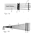
- Figures 1(a) and (b) show a schematic arrangement for phase determination in accordance with this invention where an object is illuminated by plane-wave radiation 2 or point source radiation 2 to produce reflected beams 3.
- an optical beam At each point in space, an optical beam possesses two properties: intensity and phase. Intensity is a measure of the amount of energy flowing through each point, while phase gives a measure of the direction of the energy flow.
- Intensity may be measured directly, for example by recording an image on film.
- Phase is typically measured using interference with a "reference beam”.
- the present method gives a non-interferometric method for measuring phase.
- Intensity can be measured over two parallel planes A, B extending across the direction of propagation of the wave field on the side remote from the incident radiation.
- I is the intensity in the plane
- the gradient operator in the plane is denoted ⁇ ⁇
- k is the wave number of the radiation
- ⁇ l / ⁇ z is the intensity derivative or rate of change of intensity. Note that ⁇ l / ⁇ z is estimated from the difference of the measurements in the planes A & B shown in Figure 1, while the intensity I is given by the average of the measurements.
- a suitably-well-behaved function f(x,y) may be written in the form of a two-dimensional Fourier integral:
- the function f ( k x , k y ) is called the "Fourier transform" of f(x,y).
- F denotes Fourier transformation
- F -1 denotes inverse Fourier transformation
- (k x k y ) are the Fourier variables conjugate to (x,y)
- k 2 r k 2 x + k 2 y .
- Equations (13) can be used to rewrite equation (10) in the form
- Equation (14) relating to the experimental setup in use to quantify the variables k x , k y . This can be done by rewriting equation (14) in the following form suitable for implementation using a fast Fourier transform:
- the pixel size can be determined directly for example from the CCD detector geometry (in the case of direct imaging), or by existing techniques for calibrating the transverse distance scales (in the case of an imaging system), the defocus distance can be measured directly, and the spectral distribution of the illumination can be determined either by monochromating the incident field or by analysing the spectral distribution of the radiation using existing spectroscopic methods.
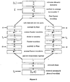
- phase-retrieval method implementing the solution of equation (14) can be represented by the flowchart shown in Figure 2.
- the quantitative determination of phase of a radiation wave field proceeds from a set of intensity measurements ⁇ I n ⁇ over the two spaced apart planes A and B.
- a measurement of central intensity I(x,y) in a selected plane parallel to and midway between the planes A and B is also obtained.
- the intensity measurements are performed over a defined array on each of the two planes A and B and the respective values subtracted to produce a measure of the intensity derivative. This value is multiplied by the negative of the average wave number.
- the data are split into two component sets and a fast Fourier transform is performed to produce the respective x and y components in the Fourier domain.
- a filter is then applied to the Fourier domain representations to correspond to the inversion of a differential operator reflected in the untransformed representation.
- the differential operator is represented by ⁇ -1 / x ⁇ 2 / ⁇ for the x component and ⁇ -1 / y ⁇ 2 / ⁇ for the y component.
- An inverse Fourier transform is then performed on each of the x and y components to produce a spatial domain value from which the differential operator has been removed.
- a division by the central intensity I(x,y) obtained by averaging the intensity measurements over planes A and B is then performed if the intensity level is above a selected threshold level.
- the resultant data is again Fourier transformed and multiplied by the same filter to again correspond to the inversion of a differential operator reflected in the untransformed data.
- the differential operator is again represented by ⁇ -1 / x ⁇ 2 / ⁇ for the x component and ⁇ -1 / y ⁇ 2 / y ⁇ for the y component .
- the resultant components are again inverse Fourier transformed and summed to provide a retrieved phase measurement.
- the method according to this invention can proceed from any suitable representative determination of intensity derivative or rate of change of intensity over a selected surface extending across the propagation direction and the intensity over that same surface.
- these data can be obtained in a variety of ways and the method implemented to yield phase of the radiation wave field.
- the solution to the transport of intensity equation (1) assumes a perfect imaging system. That is, there are no "aberrations" present in the optical system used to obtain the intensity data which is fed into the algorithm. Of course, no imaging system is perfect.
- the imperfections present in an imaging system may be quantified by a set of numbers: (16) A 1 , A 2 , A 3 ,... which are termed aberration coefficients.
- phase-retrieval algorithm For the special case of a non-absorbing phase object in a radiation wave field of uniform intensity with weak (i.e. much less than 2 ⁇ radians) phase variations the appropriate modified filters lead to the following functional form for the phase-retrieval algorithm: where:
- ⁇ I aberrated ( x , y )-1 ⁇ is a measure of rate of change of intensity.
- I 0 intensity is a measurable constant for uniform intensity so that (20) is the same general form as (15). Consequently the special case of aberration can be dealt with by changing the filter in the general method described above.
- the x and y component filters ⁇ x and ⁇ y are given by
- FIG. 1(a) A simulation was conducted in accordance with the arrangement shown in Figure 1(a) corresponding to planar illumination.
- the example shows the operation of the method on simulated noise-free data.
- Diffraction patterns are calculated using the "angular-spectrum" formalism, an orthodox procedure.
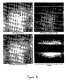
- Figures 3(a) to 3(f) show images produced in the simulation.
- Figures 3(b) and (f) are plotted on the same greyscale levels, indicating that the recovered phase is quantitatively correct.
- Figures 4(c) through (e) respectively show the propagated intensity at propagation distances of 199,200 and 201 mm; note the intermixing of information from Figures 4 (a) and (b) in the intensity measurements of Figures 4 (c), (d) and (e).
- the phase-retrieval algorithm obtained the phase map given in Figure 4(f) for the phase of the propagated field at distance 200 mm.
- Images of Figures (d) and (f) were used to numerically back-propagate the field back to the initial plane. This gave Figures 4(g) and (h) for the back-propagated intensity and phase, respectively.
- radiation such as X-rays, visible light or electrons from a point source 10 is allowed to propagate through free space to the object 11, located at a distance d so from the source.
- the radiation passes through the object 11, and is allowed to propagate a further distance d od to one of the image planes I 1 , I 2 ...I n in which the intensity of the radiation is detected.
- This detection is performed using a standard device such as a CCD camera, image plate or other device capable of registering and digitising the intensity distribution.
- One or both of the distances d so and/or d sd is then changed so as to introduce defocus into the images and the intensity distribution is measured once again.
- the case of d od 0 corresponding to contact-imaging with zero propagation distance is included as one possible measurement.
- the intensity data is then processed using the above phase recovery method, to recover the decoupled intensity and phase information in the imaging plane.
- Parameters such as wavelength, pixel size, and defocus distances are inserted into the algorithm as explained above, to yield quantitative information about the magnitude of the phase shift in the image plane.
- a reconstruction of the object in the object plane, as opposed to the downstream diffraction planes I 1 ...I n is desired.
- the intensity and quantitative phase information obtained above can be used to back propagate the light field to the object plane, thereby numerically reconstructing an image of the actual object phase and intensity structure. This can be done using standard diffraction code.
- Figure 6 schematically shows an arrangement for quantitative phase amplitude microscopy.
- a sample is illuminated using a source of white light. Köhler illumination 15, commonly found on optical microscopes.
- the light is transmitted through an object 16 and collected by a microscope imaging system 17 and relayed to a CCD camera 18 or other digital imaging device having a planar imaging surface.
- Three images are collected: an in-focus image, I o , and two slightly out of focus images I + and I - .
- the defocus is obtained by suitable means such as a drive system 19 to adjust the microscope focus knob.
- the defocus introduced is usually quite small so that degradation in spatial resolution is minimised, although the optimal amount of defocus to use is determined by sample properties and imaging geometry such as magnification, numerical apertures, etc.
- the numerical aperture of the condenser is chosen to be less than the numerical aperture of the objective being used. If this is not the case then serious image degradation will occur, although the precise amount by which the condenser and objective numerical apertures should differ involves a tradeoff between image fidelity and spatial resolution, with the optimal difference depending on the sample properties and the optics used.
- Intensity data from the collected images I + and I - are subtracted to produce a representative measure of rate of change of intensity (intensity derivative). From this and the intensity data of collected image I o the method described above can be used to produce quantitative information about the magnitude of the phase shift in the image plane.
- Example 2 for point projection, there may be cases in which it is desirable to take more than two images in order to obtain a better estimate of the intensity derivative dl/dz.
- a function can then be fitted to this data from which dl/dz can be computed and used in the phase determination method in place of the simple subtraction of two images normally used.
- FIG. 7 An experimental implementation is shown in Figure 7.
- An Olympus BX-60 optical microscope 20 was equipped with a set of UMPlan metallurgical objectives and a universal condenser to provide Köhler illumination.
- Nomarski DIC optics and a set of cover-slip corrected UplanApo objectives were also acquired for this microscope, enabling images to be taken of the same field of view using both phase retrieval and Nomarski DIC for the purposes of qualitative comparison.
- a 12-bit scientific grade Photometrics SenSys CCD camera 21 equipped with a 1300x1035 pixel Kodak KAF-1400 CCD chip was added to the 0.5x video port on the microscope to acquire digital images of the sample.
- phase recovery technique of this embodiment of the invention' requires the acquisition of defocused images.
- a stepper motor drive system 22 was attached to the focus knob of the microscope. This stepper motor 22 was attached to the parallel port of a 133MHz Pentium PC 23 also used to control the CCD camera 21, enabling full automation of the acquisition of through-focus image sequences.
- This data acquisition system was linked to custom software written to recover phase images from the CCD images, thereby enabling full automation of the image acquisition and data processing sequences.
- phase imaging using this invention can accurately measure the phase structure of microscopic samples it was necessary to have a sample with a well-characterised geometry and refractive index distribution.
- a 3M F-SN-3224 optical fibre (a commercial fibre made by 3M) was used. Independent measurements of the refractive index distribution obtained using atomic force microscopy and commercial profiling techniques were available enabling accurate prediction of the phase structure of the exit wave field.
- Another advantage of this fibre was that it had three regions of different refractive indices, an inner and outer cladding as well as the core, whereas most fibres simply have a cladding and core. This provided an additional test for the phase imaging system because it had to accurately image three transitions in refractive index rather than just two.
- the optical fibre was imaged side-on so as to obtain a projection of the refractive index through all layers of the fibre structure. This was done by first stripping the plastic sheath from the fibre by soaking it in isopropyl alcohol then using a commercial fibre stripper to remove the plastic coating. A small segment of fibre, typically a strand of approximately one to two centimetres in length, was placed on a microscope slide, immersed in a pool of index matching fluid and covered with a 0.15mm thick cover glass. Any tilt on the cover glass would introduce a spurious tilt into the recovered phase so two small sections of fibre, both of similar diameter to the sample, were placed parallel to and about 0.5cm either side of the main fibre. The cover class was then placed across all three fibres to ensure that it was as parallel to the microscope slide as practically possible.
- Figure 9 shows a comparison of the measured and expected phase profiles with the uncertainties indicated in the figure representing one standard deviation of the data along the length of the fibre. This variation is thought to be primarily due to spatial variations in thickness of the cover glass and microscope slide. As can be seen, the recovered and expected phase profiles are in good agreement with one another, with the predicted profile lying within the error bars of the profile produced using the technique of this invention.
- This example demonstrates the application of quantitative phase microscopy to the three-dimensional imaging of objects through the use of computed-tomography techniques. This is possible using the techniques of this invention because the phase shifts introduced by the object can be directly measured independently of any intensity variations in the object, thus an inverse Radon transform can be used to recover the three-dimensional structure directly from the projection data.
- an inverse Radon transform can be used to recover the three-dimensional structure directly from the projection data.
- the previously described arrangements included a stepper motor drive system 22 attached to the parallel port of the same 133MHz Pentium PC used to control the CCD camera 21 to drive the focus knob of the microscope.
- a second stepper motor 25 was connected to the second channel of the motor drive system 24 for the purposes of rotating the sample.
- This data acquisition system was linked to custom software written to recover phase images from the CCD images, thereby enabling full automation of the image acquisition and data processing sequence.
- Each data set was collected using the same microscope as in Example 3 - an Olympus BX-60 optical microscope equipped with a set of cover-slip corrected UplanApo objectives and a universal condenser to provide Köhler illumination.
- Digital images were captured using a 12-bit Photometrics SenSys CCD camera equipped with a Kodak KAF-1400 1300x1035 pixel CCD chip on the 0.5x video port of the microscope.
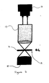
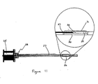
- the plastic sheath was removed from a small segment of the end of a section of fibre, typically about one centimetre in length, by soaking the fibre in isopropyl alcohol then using a commercial fibre stripper to remove the plastic coating. The fibre was then cut into a small segment of approximately one inch in length, with the unstripped end then being slid into the end of a 26 gauge, 100mm syringe needle 27 and fixed into position with a small' amount of 5 minute Araldite. A mount 28 was used to attach the needle 27 to stepper motor 25. A pool of index-matching fluid 29 surrounds the fibre 26 as shown in Figure 11, with a microscope slide 30 affixed underneath the fibre using silicone grease and a 0.15mm thick cover glass 31 placed over the top.
- the images taken were 500x500 pixels in size which conveniently spanned not only the width of the fibre but also the whole region of precession.
- As the refractive index profile of this fibre was known for 632.8nm (HeNe laser) light, a 625 ⁇ 10nm band-pass interference filter was inserted into the illumination system to ensure that the recovered phase profiles were obtained at a wavelength as close as possible to that for which data on the fibre was available.
- Each phase image was processed from images taken at ⁇ 2 ⁇ m either side of best focus, and data was collected from 100 independent angles through 180 degrees equally spaced in steps of 1.8 degrees between images.
- a typical tomographic phase image is shown in Figure 12.
- the projection data in the form the reconstructed phase images, were then processed into three-dimensional data sets using a simple slice-by-slice implementation of the summation of filtered back-projections algorithm, with code to perform the tomographic reconstruction written in the IDUPV-Wave programming language.
- the data sets were aligned to a common rotation axis by taking profiles through the phase data sets and compiling them into a sinogram.
- a sinusoid was then fitted to prominent features on the data in order to determine the location of the rotation axis and the data was digitally shifted so that the rotation axis coincided with the middle column of the sinogram to simplify the reconstruction process.
- Fitting a curve to the phase profiles also enabled misaligned data sets to be moved back into line, which in turn improved the quality of the reconstructed image.
- This realigned projection data was then transformed into a single slice through the object by back-projecting the collated phase data after filtering the projections to suppress the 1/ r point spread function associated with back-projected reconstructions. These slices through the object were then stacked up on top of each other to produce a full three-dimensional refractive index distribution of the sample.
- FIG. 13 A slice through the reconstructed refractive index distribution is shown in Figure 13. Note that all three regions of different refractive index are clearly resolved and that these regions form concentric cylinders, as is expected for this sample.
- a line profile through the centre of this reconstruction is shown in Figure 13 (dashed line) alongside the known refractive index distribution for this fibre (solid line). The values in the tomographic reconstruction are very close to those of the known profile, which confirms the quantitative phase tomography technique.
Landscapes
- Physics & Mathematics (AREA)
- General Physics & Mathematics (AREA)
- Engineering & Computer Science (AREA)
- Spectroscopy & Molecular Physics (AREA)
- Signal Processing (AREA)
- Theoretical Computer Science (AREA)
- Optics & Photonics (AREA)
- Mathematical Physics (AREA)
- Analysing Materials By The Use Of Radiation (AREA)
- Investigating Or Analysing Materials By Optical Means (AREA)
- Control Of High-Frequency Heating Circuits (AREA)
- Inorganic Insulating Materials (AREA)
- Power Steering Mechanism (AREA)
- Apparatus For Radiation Diagnosis (AREA)
- Investigating Or Analyzing Materials By The Use Of Ultrasonic Waves (AREA)
- Length Measuring Devices By Optical Means (AREA)
- Measurement Of Radiation (AREA)
Applications Claiming Priority (3)
| Application Number | Priority Date | Filing Date | Title |
|---|---|---|---|
| AUPP690098 | 1998-11-02 | ||
| AUPP6900A AUPP690098A0 (en) | 1998-11-02 | 1998-11-02 | Phase determination of a radiation wave field |
| EP99957223A EP1127252B1 (fr) | 1998-11-02 | 1999-11-01 | Determination de phases d'un champ d'ondes de rayonnement |
Related Parent Applications (1)
| Application Number | Title | Priority Date | Filing Date |
|---|---|---|---|
| EP99957223A Division EP1127252B1 (fr) | 1998-11-02 | 1999-11-01 | Determination de phases d'un champ d'ondes de rayonnement |
Publications (2)
| Publication Number | Publication Date |
|---|---|
| EP1505376A1 true EP1505376A1 (fr) | 2005-02-09 |
| EP1505376B1 EP1505376B1 (fr) | 2015-05-27 |
Family
ID=3811114
Family Applications (2)
| Application Number | Title | Priority Date | Filing Date |
|---|---|---|---|
| EP99957223A Expired - Lifetime EP1127252B1 (fr) | 1998-11-02 | 1999-11-01 | Determination de phases d'un champ d'ondes de rayonnement |
| EP04027179.3A Expired - Lifetime EP1505376B1 (fr) | 1998-11-02 | 1999-11-01 | Formation d'image d'un objet avec détermination de phases d'un champ d'ondes de rayonnement |
Family Applications Before (1)
| Application Number | Title | Priority Date | Filing Date |
|---|---|---|---|
| EP99957223A Expired - Lifetime EP1127252B1 (fr) | 1998-11-02 | 1999-11-01 | Determination de phases d'un champ d'ondes de rayonnement |
Country Status (15)
| Country | Link |
|---|---|
| US (2) | US6885442B1 (fr) |
| EP (2) | EP1127252B1 (fr) |
| JP (1) | JP4391698B2 (fr) |
| KR (1) | KR100642388B1 (fr) |
| CN (1) | CN100402996C (fr) |
| AT (1) | ATE290687T1 (fr) |
| AU (1) | AUPP690098A0 (fr) |
| BR (1) | BR9914976A (fr) |
| CA (1) | CA2348912C (fr) |
| DE (1) | DE69924136T2 (fr) |
| ES (1) | ES2239854T3 (fr) |
| RU (1) | RU2237871C2 (fr) |
| TW (1) | TW487810B (fr) |
| WO (1) | WO2000026622A1 (fr) |
| ZA (1) | ZA200103169B (fr) |
Cited By (2)
| Publication number | Priority date | Publication date | Assignee | Title |
|---|---|---|---|---|
| EP3712596A4 (fr) * | 2017-11-14 | 2021-11-24 | Nikon Corporation | Procédé de génération d'image de phase quantitative, dispositif de génération d'image de phase quantitative et programme |
| WO2023165667A1 (fr) * | 2022-03-01 | 2023-09-07 | Danmarks Tekniske Universitet | Imagerie de champ lumineux basée sur une aberration d'inclinaison |
Families Citing this family (35)
| Publication number | Priority date | Publication date | Assignee | Title |
|---|---|---|---|---|
| AUPR672601A0 (en) * | 2001-07-31 | 2001-08-23 | Iatia Imaging Pty Ltd | Apparatus and method of imaging an object |
| AUPR830801A0 (en) * | 2001-10-16 | 2001-11-08 | Iatia Imaging Pty Ltd | Phase determination of a radiation wavefield |
| US20070182844A1 (en) * | 2003-03-09 | 2007-08-09 | Latia Imaging Pty Ltd | Optical system for producing differently focused images |
| JP4662935B2 (ja) * | 2003-09-23 | 2011-03-30 | イアティア イメージング プロプライアタリー リミティド | 試料の面積またはコンフルエンスを決定するための方法と装置 |
| WO2005083377A1 (fr) * | 2004-03-01 | 2005-09-09 | Iatia Imaging Pty Ltd | Procede et appareil de production d'une image renfermant des informations de profondeur |
| GB0409572D0 (en) * | 2004-04-29 | 2004-06-02 | Univ Sheffield | High resolution imaging |
| US20080094634A1 (en) * | 2004-10-01 | 2008-04-24 | Jacob Rubinstein | Phase Determination System and Method |
| FR2881520B1 (fr) * | 2005-02-03 | 2007-10-12 | Lyuboshenko Igor | Obtention d'une image de phase a partir d'une image d'intensite |
| DE102007009661A1 (de) * | 2006-08-31 | 2008-03-13 | Carl Zeiss Sms Gmbh | Verfahren und Vorrichtung zur ortsaufgelösten Bestimmung der Phase und Amplitude des elektromagnetischen Feldes in der Bildebene einer Abbildung eines Objektes |
| DE102006061978A1 (de) * | 2006-12-21 | 2008-06-26 | Forschungszentrum Jülich GmbH | Elektronenmikroskop und Verfahren zur Messung der Defokusstreuung |
| US7564545B2 (en) * | 2007-03-15 | 2009-07-21 | Kla-Tencor Technologies Corp. | Inspection methods and systems for lithographic masks |
| AU2008278275A1 (en) * | 2007-07-18 | 2009-01-22 | Iatia Imaging Pty Ltd | Method and apparatus for determining the surface profile of an object |
| ES2369432B2 (es) * | 2007-09-27 | 2012-05-03 | Universidade De Santiago De Compostela | Procedimiento para la optimización de la medida de la derivada direccional de la intensidad de radiación electromagnética y dispositivo para su puesta en pr�?ctica. |
| JP2009186679A (ja) * | 2008-02-05 | 2009-08-20 | Olympus Corp | 観察装置 |
| DE102009019514A1 (de) | 2009-04-30 | 2010-11-11 | Siemens Aktiengesellschaft | CT-System und Verfahren zur Phasenkontrast- und Absorptionsbildgebung |
| GB2495537B (en) | 2011-10-14 | 2017-02-15 | Solentim Ltd | Method of and apparatus for analysis of a sample of biological tissue cells |
| US9423307B2 (en) | 2013-02-20 | 2016-08-23 | Mesa Photonics, LLC | Method and apparatus for determining wave characteristics using interaction with a known wave |
| JP6730659B2 (ja) * | 2016-02-17 | 2020-07-29 | 日本電気株式会社 | 透過波面測定方法、装置およびシステム |
| DE102016203275B4 (de) * | 2016-02-29 | 2019-07-18 | Carl Zeiss Industrielle Messtechnik Gmbh | Verfahren und Vorrichtung zur Bestimmung eines Defokussierungswerts und Verfahren und Vorrichtung zur bildbasierten Bestimmung einer dimensionellen Größe |
| DE102016114375A1 (de) | 2016-08-03 | 2018-02-08 | Humboldt-Universität Zu Berlin | Vorrichtung zur Erzeugung einer Bildserie |
| JP2018180296A (ja) | 2017-04-13 | 2018-11-15 | 横河電機株式会社 | 顕微鏡システム、顕微鏡、処理装置、及び顕微鏡用カメラ |
| CN107942147B (zh) * | 2017-11-15 | 2019-09-20 | 北京邮电大学 | 一种天线的远场方向图的测量方法和装置 |
| US10274378B1 (en) | 2018-04-26 | 2019-04-30 | Mesa Photonics, LLC | Method and apparatus for determining wave characteristics using constrained interactions of waves |
| FR3091347B1 (fr) * | 2018-12-26 | 2021-11-05 | Commissariat Energie Atomique | Procédé de caractérisation d'un échantillon par imagerie de phase |
| US11501420B2 (en) | 2019-09-26 | 2022-11-15 | Perkinelmer Cellular Technologies Germany Gmbh | Reconstructing phase images with deep learning |
| US11362481B2 (en) | 2020-05-01 | 2022-06-14 | Mesa Photonics, LLC | Method and apparatus for measuring optical pulses |
| US11237059B1 (en) * | 2020-12-14 | 2022-02-01 | Gerchberg Ophthalmic Dispensing, PLLC | Totagraphy: Coherent diffractive/digital information reconstruction by iterative phase recovery using special masks |
| CN112540460A (zh) * | 2020-12-29 | 2021-03-23 | 华东交通大学 | 基于tir与微透镜阵列组合的光学系统设计方法 |
| CN113376448B (zh) * | 2021-04-29 | 2023-02-28 | 北京邮电大学 | 一种用于紧缩场测试中静区相位恢复的方法及装置 |
| WO2023039702A1 (fr) * | 2021-09-14 | 2023-03-23 | Shenzhen Xpectvision Technology Co., Ltd. | Imagerie par rayons x en microscopie à expansion |
| US12579803B2 (en) | 2022-02-01 | 2026-03-17 | Wavefront Analysis Systems Llc | Totagraphy for superresolution imaging and signal processing of positive, real-valued images and signals |
| US12388639B2 (en) | 2022-02-01 | 2025-08-12 | Wavefront Analysis Systems Llc | Encryption and decryption using phase recovery |
| CN114912347B (zh) * | 2022-04-12 | 2025-10-24 | 中国辐射防护研究院 | 一种未知源项辐射场重构方法、存储介质及系统 |
| CN116399551B (zh) * | 2023-06-06 | 2023-08-04 | 中国航空工业集团公司沈阳空气动力研究所 | 一种用于高超声速风洞的模型三维密度场测量方法 |
| CN119395872B (zh) * | 2024-10-23 | 2025-05-16 | 广东工业大学 | 基于pix2pix网络的微分干涉相衬显微术相位重构方法 |
Citations (1)
| Publication number | Priority date | Publication date | Assignee | Title |
|---|---|---|---|---|
| US5633714A (en) * | 1994-12-19 | 1997-05-27 | International Business Machines Corporation | Preprocessing of image amplitude and phase data for CD and OL measurement |
Family Cites Families (14)
| Publication number | Priority date | Publication date | Assignee | Title |
|---|---|---|---|---|
| US4309602A (en) * | 1979-11-01 | 1982-01-05 | Eikonix Corportation | Wavefront sensing by phase retrieval |
| US4690555A (en) * | 1985-11-01 | 1987-09-01 | Hughes Aircraft Company | Solid-state wavefront slope determination |
| CH678663A5 (fr) | 1988-06-09 | 1991-10-15 | Zeiss Carl Fa | |
| JP2563134B2 (ja) | 1989-01-25 | 1996-12-11 | 日本電子株式会社 | 走査透過型位相差電子顕微鏡 |
| RU2028577C1 (ru) * | 1990-11-16 | 1995-02-09 | Санкт-Петербургский технологический институт холодильной промышленности | Способ измерения оптической разности фаз |
| JP3039563B2 (ja) | 1990-11-29 | 2000-05-08 | 株式会社日立製作所 | 走査電子顕微鏡及び走査電子顕微方法 |
| RU2023982C1 (ru) * | 1991-06-28 | 1994-11-30 | Московский государственный технологический университет "СТАНКИН" | Интерференционный способ измерения фазового сдвига световых волн |
| US5367375A (en) * | 1992-02-07 | 1994-11-22 | Hughes Aircraft Company | Spatial wavefront evaluation by intensity relationship |
| KR960019415A (ko) * | 1994-11-23 | 1996-06-17 | 윤종용 | 플라즈마 표시 패널 |
| AUPN201295A0 (en) | 1995-03-28 | 1995-04-27 | Commonwealth Scientific And Industrial Research Organisation | Simplified conditions and configurations for phase-contrast imaging with hard x-rays |
| JPH09187455A (ja) | 1996-01-10 | 1997-07-22 | Hitachi Ltd | 位相型x線ct装置 |
| AU716800B2 (en) * | 1996-12-24 | 2000-03-09 | Xrt Limited | Phase retrieval in phase contrast imaging |
| US5841125A (en) * | 1997-06-06 | 1998-11-24 | Trw Inc. | High energy laser focal sensor (HELFS) |
| US6219142B1 (en) * | 1997-10-17 | 2001-04-17 | Southwest Sciences Incorporated | Method and apparatus for determining wave characteristics from wave phenomena |
-
1998
- 1998-11-02 AU AUPP6900A patent/AUPP690098A0/en not_active Abandoned
-
1999
- 1999-11-01 CN CNB99812916XA patent/CN100402996C/zh not_active Expired - Fee Related
- 1999-11-01 DE DE69924136T patent/DE69924136T2/de not_active Expired - Lifetime
- 1999-11-01 BR BR9914976-1A patent/BR9914976A/pt not_active IP Right Cessation
- 1999-11-01 WO PCT/AU1999/000949 patent/WO2000026622A1/fr not_active Ceased
- 1999-11-01 EP EP99957223A patent/EP1127252B1/fr not_active Expired - Lifetime
- 1999-11-01 JP JP2000579955A patent/JP4391698B2/ja not_active Expired - Fee Related
- 1999-11-01 RU RU2001115107A patent/RU2237871C2/ru not_active IP Right Cessation
- 1999-11-01 ES ES99957223T patent/ES2239854T3/es not_active Expired - Lifetime
- 1999-11-01 KR KR1020017005491A patent/KR100642388B1/ko not_active Expired - Fee Related
- 1999-11-01 CA CA002348912A patent/CA2348912C/fr not_active Expired - Fee Related
- 1999-11-01 AT AT99957223T patent/ATE290687T1/de not_active IP Right Cessation
- 1999-11-01 EP EP04027179.3A patent/EP1505376B1/fr not_active Expired - Lifetime
- 1999-11-01 US US09/830,393 patent/US6885442B1/en not_active Expired - Lifetime
- 1999-11-02 TW TW088119033A patent/TW487810B/zh not_active IP Right Cessation
-
2001
- 2001-04-18 ZA ZA200103169A patent/ZA200103169B/en unknown
-
2004
- 2004-11-02 US US10/979,554 patent/US7039553B2/en not_active Expired - Lifetime
Patent Citations (1)
| Publication number | Priority date | Publication date | Assignee | Title |
|---|---|---|---|---|
| US5633714A (en) * | 1994-12-19 | 1997-05-27 | International Business Machines Corporation | Preprocessing of image amplitude and phase data for CD and OL measurement |
Cited By (2)
| Publication number | Priority date | Publication date | Assignee | Title |
|---|---|---|---|---|
| EP3712596A4 (fr) * | 2017-11-14 | 2021-11-24 | Nikon Corporation | Procédé de génération d'image de phase quantitative, dispositif de génération d'image de phase quantitative et programme |
| WO2023165667A1 (fr) * | 2022-03-01 | 2023-09-07 | Danmarks Tekniske Universitet | Imagerie de champ lumineux basée sur une aberration d'inclinaison |
Also Published As
| Publication number | Publication date |
|---|---|
| ES2239854T3 (es) | 2005-10-01 |
| US20050062957A1 (en) | 2005-03-24 |
| EP1127252A1 (fr) | 2001-08-29 |
| EP1127252A4 (fr) | 2002-03-13 |
| KR100642388B1 (ko) | 2006-11-03 |
| CN1334916A (zh) | 2002-02-06 |
| CN100402996C (zh) | 2008-07-16 |
| DE69924136D1 (de) | 2005-04-14 |
| EP1505376B1 (fr) | 2015-05-27 |
| CA2348912A1 (fr) | 2000-05-11 |
| RU2237871C2 (ru) | 2004-10-10 |
| KR20010080375A (ko) | 2001-08-22 |
| TW487810B (en) | 2002-05-21 |
| ATE290687T1 (de) | 2005-03-15 |
| US6885442B1 (en) | 2005-04-26 |
| BR9914976A (pt) | 2001-07-24 |
| JP4391698B2 (ja) | 2009-12-24 |
| JP2002529689A (ja) | 2002-09-10 |
| DE69924136T2 (de) | 2006-04-13 |
| WO2000026622A1 (fr) | 2000-05-11 |
| ZA200103169B (en) | 2002-08-19 |
| US7039553B2 (en) | 2006-05-02 |
| AUPP690098A0 (en) | 1998-11-26 |
| CA2348912C (fr) | 2008-01-08 |
| EP1127252B1 (fr) | 2005-03-09 |
Similar Documents
| Publication | Publication Date | Title |
|---|---|---|
| EP1127252B1 (fr) | Determination de phases d'un champ d'ondes de rayonnement | |
| US7649160B2 (en) | Wave front sensing method and apparatus | |
| Liebling et al. | Complex-wave retrieval from a single off-axis hologram | |
| EP2206008B1 (fr) | Microscope optique à nouveau procédé numérique permettant d'obtenir une super-résolution | |
| Preza | Rotational-diversity phase estimation from differential-interference-contrast microscopy images | |
| Bostan et al. | Variational phase imaging using the transport-of-intensity equation | |
| Trusiak et al. | Hilbert-Huang processing for single-exposure two-dimensional grating interferometry | |
| WO2011033287A1 (fr) | Procédé et appareil pour récupérer une phase d'un champ d'ondes | |
| US20150100278A1 (en) | Systems and methods for quantitative phase imaging with partially coherent illumination | |
| Zhou et al. | Fast automatic multiple positioning for lensless coherent diffraction imaging | |
| Dong et al. | Automatic filtering for zero-order and twin-image elimination in off-axis digital holography | |
| Shield et al. | Diffraction theory of optical interference moiré and a device for production of variable virtual reference gratings: A moiré microscope | |
| US8693091B2 (en) | Optical microscope system and method carried out therewith for reconstructing an image of an object | |
| AU766636B2 (en) | Phase determination of a radiation wave field | |
| Larkin et al. | Direct method for phase retrieval from the intensity of cylindrical wave fronts | |
| GB2474442A (en) | Retrieving a phase of a wavefield | |
| WO2003034010A1 (fr) | Determination de phase de champ d'onde de rayonnement | |
| Preza et al. | Image reconstruction for three-dimensional transmitted-light DIC microscopy | |
| Kus et al. | Limited-angle hybrid diffraction tomography for biological samples | |
| CN112258628B (zh) | 一种基于光栅相位衬度的成像系统及方法 | |
| Bao | Theory, Development, and Application of Quantitative Phase Imaging Modalities on Standard Microscope Platforms | |
| Preza et al. | Phase estimation from transmitted-light DIC images using rotational diversity | |
| Wei et al. | Single-shot lensless imaging based on iterative denoising phase retrieval | |
| von Hofsten et al. | Simulation of partially coherent image formation in x-ray microscopy |
Legal Events
| Date | Code | Title | Description |
|---|---|---|---|
| PUAI | Public reference made under article 153(3) epc to a published international application that has entered the european phase |
Free format text: ORIGINAL CODE: 0009012 |
|
| AC | Divisional application: reference to earlier application |
Ref document number: 1127252 Country of ref document: EP Kind code of ref document: P |
|
| AK | Designated contracting states |
Kind code of ref document: A1 Designated state(s): AT BE CH CY DE DK ES FI FR GB GR IE IT LI LU MC NL PT SE |
|
| AX | Request for extension of the european patent |
Extension state: AL LT LV MK |
|
| 17P | Request for examination filed |
Effective date: 20050620 |
|
| AKX | Designation fees paid |
Designated state(s): DE ES FR GB IT |
|
| 17Q | First examination report despatched |
Effective date: 20071127 |
|
| GRAP | Despatch of communication of intention to grant a patent |
Free format text: ORIGINAL CODE: EPIDOSNIGR1 |
|
| INTG | Intention to grant announced |
Effective date: 20141202 |
|
| GRAS | Grant fee paid |
Free format text: ORIGINAL CODE: EPIDOSNIGR3 |
|
| GRAA | (expected) grant |
Free format text: ORIGINAL CODE: 0009210 |
|
| AC | Divisional application: reference to earlier application |
Ref document number: 1127252 Country of ref document: EP Kind code of ref document: P |
|
| AK | Designated contracting states |
Kind code of ref document: B1 Designated state(s): DE ES FR GB IT |
|
| REG | Reference to a national code |
Ref country code: GB Ref legal event code: FG4D |
|
| REG | Reference to a national code |
Ref country code: DE Ref legal event code: R096 Ref document number: 69945341 Country of ref document: DE Effective date: 20150702 |
|
| PG25 | Lapsed in a contracting state [announced via postgrant information from national office to epo] |
Ref country code: ES Free format text: LAPSE BECAUSE OF FAILURE TO SUBMIT A TRANSLATION OF THE DESCRIPTION OR TO PAY THE FEE WITHIN THE PRESCRIBED TIME-LIMIT Effective date: 20150527 |
|
| REG | Reference to a national code |
Ref country code: DE Ref legal event code: R097 Ref document number: 69945341 Country of ref document: DE |
|
| PLBE | No opposition filed within time limit |
Free format text: ORIGINAL CODE: 0009261 |
|
| STAA | Information on the status of an ep patent application or granted ep patent |
Free format text: STATUS: NO OPPOSITION FILED WITHIN TIME LIMIT |
|
| PG25 | Lapsed in a contracting state [announced via postgrant information from national office to epo] |
Ref country code: IT Free format text: LAPSE BECAUSE OF FAILURE TO SUBMIT A TRANSLATION OF THE DESCRIPTION OR TO PAY THE FEE WITHIN THE PRESCRIBED TIME-LIMIT Effective date: 20150527 |
|
| 26N | No opposition filed |
Effective date: 20160301 |
|
| REG | Reference to a national code |
Ref country code: FR Ref legal event code: PLFP Year of fee payment: 18 |
|
| PGFP | Annual fee paid to national office [announced via postgrant information from national office to epo] |
Ref country code: FR Payment date: 20161125 Year of fee payment: 18 Ref country code: GB Payment date: 20161124 Year of fee payment: 18 Ref country code: DE Payment date: 20161125 Year of fee payment: 18 |
|
| REG | Reference to a national code |
Ref country code: DE Ref legal event code: R119 Ref document number: 69945341 Country of ref document: DE |
|
| GBPC | Gb: european patent ceased through non-payment of renewal fee |
Effective date: 20171101 |
|
| REG | Reference to a national code |
Ref country code: FR Ref legal event code: ST Effective date: 20180731 |
|
| PG25 | Lapsed in a contracting state [announced via postgrant information from national office to epo] |
Ref country code: FR Free format text: LAPSE BECAUSE OF NON-PAYMENT OF DUE FEES Effective date: 20171130 Ref country code: DE Free format text: LAPSE BECAUSE OF NON-PAYMENT OF DUE FEES Effective date: 20180602 |
|
| PG25 | Lapsed in a contracting state [announced via postgrant information from national office to epo] |
Ref country code: GB Free format text: LAPSE BECAUSE OF NON-PAYMENT OF DUE FEES Effective date: 20171101 |