EP1505389A1 - Appareil d'échantillonage de fluide personnel et environnemental - Google Patents
Appareil d'échantillonage de fluide personnel et environnemental Download PDFInfo
- Publication number
- EP1505389A1 EP1505389A1 EP03254873A EP03254873A EP1505389A1 EP 1505389 A1 EP1505389 A1 EP 1505389A1 EP 03254873 A EP03254873 A EP 03254873A EP 03254873 A EP03254873 A EP 03254873A EP 1505389 A1 EP1505389 A1 EP 1505389A1
- Authority
- EP
- European Patent Office
- Prior art keywords
- sample
- pipe
- sampling apparatus
- reservoir
- micro
- Prior art date
- Legal status (The legal status is an assumption and is not a legal conclusion. Google has not performed a legal analysis and makes no representation as to the accuracy of the status listed.)
- Withdrawn
Links
Images




Classifications
-
- G—PHYSICS
- G01—MEASURING; TESTING
- G01N—INVESTIGATING OR ANALYSING MATERIALS BY DETERMINING THEIR CHEMICAL OR PHYSICAL PROPERTIES
- G01N33/00—Investigating or analysing materials by specific methods not covered by groups G01N1/00 - G01N31/00
- G01N33/48—Biological material, e.g. blood, urine; Haemocytometers
- G01N33/483—Physical analysis of biological material
- G01N33/497—Physical analysis of biological material of gaseous biological material, e.g. breath
Definitions
- the present invention relates to a sampling device and, more particularly, to a sampling device with built-in reservoirs and pumps.
- samples for some sampling devices used for diagnosis is taken through patients' blowing or breath.
- the inlet tubes of these sampling devices are disposed and replaced after use in order to prevent the prevailing of contagious diseases and to maintain the devices to be clean.
- the operators still have chance to contact the patients' saliva and then indirectly pass the saliva to the new inlet tubes, which may cause the prevailing of the contagious diseases.
- inlet tubes of these sampling devices are designed as an extended tube protruding from the outer case of the sampling devices, the inlet tubes of these sampling devices are easy to be contaminated as the sampling devices dropped on the ground or in some polluted environment. In some cases, the contaminated inlet tubes also cause serious errors or inaccuracy for detection.
- the inlet tube may be stained by some hazard or toxicant. If the operators replace the inlet tubes by hands, the hazards or toxicants may cause serious injuries.
- breathalyser In some special cases, it is required to detect and analyze the sample in a long-term, constant flow-rate mode so as to provide more accurate result.
- a good example is the breathalyser.
- the result made by a breathalyser is based on the amount of alcohol vapors contained in one's breath. However, since the volume of each breath is different even for the same single person, thus the test results based on different breaths are not the same and depend on how deep the breaths are.
- US patent 4,947,861 a sampling method requiring operators to analyze the test result is disclosed in US patent 4,947,861.
- the sampling method in US patent 4,947,861 cannot be applied with constant sample flow-rate.
- Another sensing apparatus comprising a housing, a sensor module and a sample chamber to hold the sample is disclosed in US patent 6,234,006.
- the apparatus in US patent 6,234,006 can't be used for an inconstant flow-rate detection because there is no room for holding the sample and then transmitting the sample to the sensor module in a constant flow-rate. But for most illness detection or for the operation of hyper-sensitivity sensing apparatus, it is necessary to provide a space for sample storage to transmitting the sample to the sensor module constantly.
- An object of the present invention is to provide a sampling apparatus capable to hide or hold the sample inlet tube to prevent contamination of the inlet tube and the apparatus, and to reduce the size of the whole apparatus.
- Another object of the present invent is to provide a sampling apparatus which comprises a sampling device having a reservoir so as to provide a constant flow-rate sample for detection.
- Another object of the present invention is to provide an analyzer with reduced size for preventing possible contamination from outside environment.
- the present invention also provides a portable sampling apparatus used for detecting and analyzing a sample, includes: a housing; and a sample inlet mounted on the housing, wherein said sample inlet can rotate, flip-flop, slide, fold, or extend to be received into said housing.
- the sampling apparatus of the present invention used to detect a sample includes: a housing; a sample inlet mounted in said housing; a sensor module mounted in said housing; and a sampling device comprising a reservoir, said sampling device is used for the transporting of the sample and controls the flow rate of the sample.
- the analyzer of the present invention includes: a housing; and a sample inlet mounted on the housing, wherein said sample inlet is able to extend out from said housing through rotation, flip-flopping, sliding, folding or springing.
- FIG. 1A A schematic view of the first embodiment of the sampling apparatus is shown in FIG. 1A.
- the inlet tube 21 of the sampling apparatus can be received and folded in the concave 8 of the sampling apparatus.
- the inlet tube 21 can be received in a concave 8 or be extended from the concave 8 through folding means.
- the folding mean is the combination of holes 81, 82 and protrusion pins 211,212.
- two holes 81, 82 opposing each other can be found at one end of the concave 8 of the housing.
- two protrusion pins 211,212 corresponding to the two holes 81 are arranged to connect the holes 81, 82 on the housing.
- the inlet tube 21 is mounted on the housing.
- the two protrusion pins 211,212 inserting into the two holes function as a hinge, and thereby the inlet tube 21 can rotate by the hinge, as shown in FIG. 1B.
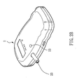
- FIG. 2A of the present invention shows a schematic view of the second embodiment.
- the inlet tube 23 of the sampling apparatus can be received in the receiving hole 25 by a holding means (not shown in the figure) when it's not applied.
- the releasing button 13 are pushed or triggered to release the holding means, and then the inlet tube flipps out from the receiving hole 25, as shown in FIG 2B.
- Other ways for receiving and holding the inlet tube in the housing of the sampling apparatus can be conceived, but not limited Preferably, these ways include sliding in and out, folding up, stretching out, or compressing in the inlet tube.
- the passing of the fluid sample is controlled by valves.
- the passing of the fluid sample is controlled through electrical micro-valves.
- the sample is stored in a reservoir as the micro-valves between the inlet tube and the reservoir are opened, the micro-valves between the reservoir and the pump are closed.
- the micro-valves between the reservoir and the pump are then opened and the micro-valves between the inlet tube and the reservoir are closed as a micro-pump creates pressure difference to transmit the sample from the reservoir to the sensor module through the pipes. All the actuation of the micro-valves and the micro-pumps are controlled by a microprocessor.
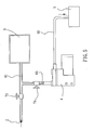
- FIG. 3 is a diagram of the third embodiment showing the components of the sampling apparatus comprising a sample inlet 2, a reservoir 3, a micro-pump 4, a sensor module 5, a first pipe 61, a second pipe 62, a third pipe 63 and a micro-valve 71, wherein the sample inlet 2 is connected to the reservoir 3 by the first pipe 61 through an opening 31 on the reservoir so that the sample coming from the sample inlet 2 can be stored in the reservoir 3.
- the micro-pump 4 is connected to the sensor module by the second pipe 62 and connected to the first pipe 61 by the third pipe 63.
- the micro-valve 71 is connected to the first pipe 61 at a position between the sample inlet 2 and the intersection of the first pipe 61 and the third pipe 63 so as to control the amount of the sample fluid.
- the microprocessor (not shown in the figure) will turn off the micro-valve 71 and turn on the micro-pump 4 to pump the sample fluid stored in the reservoir 3 to the sensor-module 5 at a constant flow rate.
- the microprocessor and a D/A converter works together to convert the digital signals to analogous signals, and then linearly amplify the analogous signals by an operational amplifier to provide the amplified voltage to drive the micro-pump 4. Therefore, the micro-pump 4 can be driven by a digital microprocessor. In this way, the sample can be pumped to the sensor-module by the operation of the micro-pump 4. By actuating micro-valve 71 and the micro-pump 4 at the same time, the sample can be transmitted from the sample inlet directly to the sensor-module 5 without storing in the reservoir 3. One can also "clean up" the sampling apparatus by simply replace the sample with a clean fluid (e.g. clean air).
- a clean fluid e.g. clean air
- FIG. 4 is the diagram of the fourth embodiment showing the modification of the third embodiment.
- the micro-valve 72 is a 3-way valve having a first exit port 721 directing to the reservoir and a second exit port 722 directing to the micro-pump 4.
- the micro-valve is connected to the first pipe 61 right at the intersection of the first pipe 61 and the third pipe 63. Therefore when the operator is doing sampling, the microprocessor turns on the first exit port 721 and turns off the second exit port 722. When doing analyzing, the microprocessor turns off the first exit port and turns on the second exit port 722 so as to pump the sample from the reservoir 3 to the sensor-module 5 at a constant flow rate.
- FIG 5 is the diagram of the fifth embodiment showing another modification of the third embodiment.
- the first micro-valve 73 in this figure remains at its position as in FIG 3.
- another connection between a second micro-valve 74 and the third pipe 63 is made. Therefore when doing sampling, the microprocessor turns on the first micro-valve 73 and turns off the second micro-valve 74 so that the sample can be conducted to the reservoir 3 rather than to the pump 4.
- the microprocessor turns off the first micro-valve 73 and turn on the second micro-valve 74 so as to pump the sample from the reservoir 3 to the sensor-module 5 at a constant flow rate.
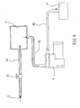
- the sixth and seventh embodiments are another type of arrangement of the piping and valves wherein the reservoir 3 comprises a first opening 32 and a second opening 33 so that the sample comes into the reservoir through the first opening 32 and being pumped out of the reservoir through the second opening 33.
- FIG. 6 This is the diagram of the sixth embodiment.
- a first micro-valve is connected to the first pipe 61, and the first pipe 61 is connected to the reservoir 3 through a first opening 32.
- the reservoir 3 is connected to the micro-pump 4 through a second opening 33.
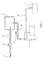
- FIG. 7 This is the diagram of the seventh embodiment which shows a modification of the sixth embodiment.
- the difference of the sixth and the seventh embodiment lies in that there is a second micro-valve 77 connecting to the third pipe 63 in the seventh embodiment. Therefore when doing sampling, the microprocessor turns on the first micro-valve 76 and turns off the second micro-valve 77 so that the sample stops and being stored in the reservoir 3. When doing analyzing, the microprocessor turns off the first micro-valve 76 and turns on the second micro-valve 77 so as to pump the sample from the reservoir 3 to the sensor-module at a constant flow rate.
- the advantages of foldable sample inlet tubes can be amplified to reduce or prevent any possible contamination.
- the embedded sample inlet tubes also reduce the size of the sampling apparatus and make the sampling apparatus much more convenient for carrying.
- the arrangement of the reservoir-pump design can provide a sample fluid in a relatively constant flow rate. Therefore, constant-rate or non-constant-rate sampling can be achieved smoothly since the buffering of the built-in reservoir can provide a fluid in a relatively constant flow rate to the sensor module.
- the sampling apparatus of the present invention provides a more stable and accurate result, as well as a faster analyzing time.
Landscapes
- Health & Medical Sciences (AREA)
- Life Sciences & Earth Sciences (AREA)
- Engineering & Computer Science (AREA)
- Molecular Biology (AREA)
- Physics & Mathematics (AREA)
- Biomedical Technology (AREA)
- Chemical & Material Sciences (AREA)
- Urology & Nephrology (AREA)
- Hematology (AREA)
- Biophysics (AREA)
- Food Science & Technology (AREA)
- Medicinal Chemistry (AREA)
- Analytical Chemistry (AREA)
- Biochemistry (AREA)
- General Health & Medical Sciences (AREA)
- General Physics & Mathematics (AREA)
- Immunology (AREA)
- Pathology (AREA)
- Sampling And Sample Adjustment (AREA)
Priority Applications (1)
| Application Number | Priority Date | Filing Date | Title |
|---|---|---|---|
| EP03254873A EP1505389A1 (fr) | 2003-08-05 | 2003-08-05 | Appareil d'échantillonage de fluide personnel et environnemental |
Applications Claiming Priority (1)
| Application Number | Priority Date | Filing Date | Title |
|---|---|---|---|
| EP03254873A EP1505389A1 (fr) | 2003-08-05 | 2003-08-05 | Appareil d'échantillonage de fluide personnel et environnemental |
Publications (1)
| Publication Number | Publication Date |
|---|---|
| EP1505389A1 true EP1505389A1 (fr) | 2005-02-09 |
Family
ID=33547788
Family Applications (1)
| Application Number | Title | Priority Date | Filing Date |
|---|---|---|---|
| EP03254873A Withdrawn EP1505389A1 (fr) | 2003-08-05 | 2003-08-05 | Appareil d'échantillonage de fluide personnel et environnemental |
Country Status (1)
| Country | Link |
|---|---|
| EP (1) | EP1505389A1 (fr) |
Cited By (1)
| Publication number | Priority date | Publication date | Assignee | Title |
|---|---|---|---|---|
| EP1850748A4 (fr) * | 2005-02-07 | 2009-05-06 | Apieron Inc | Controle de flux d'expiration en cours d'analyse |
Citations (5)
| Publication number | Priority date | Publication date | Assignee | Title |
|---|---|---|---|---|
| FR2716693A1 (fr) * | 1994-02-25 | 1995-09-01 | Laurec Francois Xavier | Clé à blocage incorporé et tête de clé permettant la constitution d'une telle clé. |
| WO1995026889A1 (fr) * | 1994-03-30 | 1995-10-12 | Drager Australia Pty. Ltd. | Dispositif de controle et embout |
| WO1998016812A1 (fr) * | 1996-10-11 | 1998-04-23 | Alcohol Sensors International, Ltd. | Appareil de surveillance de l'air expire par une personne |
| US6234006B1 (en) * | 1998-03-20 | 2001-05-22 | Cyrano Sciences Inc. | Handheld sensing apparatus |
| WO2001084112A1 (fr) * | 2000-05-01 | 2001-11-08 | Respiratory Research, Inc. | Procede et dispositif pour recueillir et analyser de l'air exhale |
-
2003
- 2003-08-05 EP EP03254873A patent/EP1505389A1/fr not_active Withdrawn
Patent Citations (5)
| Publication number | Priority date | Publication date | Assignee | Title |
|---|---|---|---|---|
| FR2716693A1 (fr) * | 1994-02-25 | 1995-09-01 | Laurec Francois Xavier | Clé à blocage incorporé et tête de clé permettant la constitution d'une telle clé. |
| WO1995026889A1 (fr) * | 1994-03-30 | 1995-10-12 | Drager Australia Pty. Ltd. | Dispositif de controle et embout |
| WO1998016812A1 (fr) * | 1996-10-11 | 1998-04-23 | Alcohol Sensors International, Ltd. | Appareil de surveillance de l'air expire par une personne |
| US6234006B1 (en) * | 1998-03-20 | 2001-05-22 | Cyrano Sciences Inc. | Handheld sensing apparatus |
| WO2001084112A1 (fr) * | 2000-05-01 | 2001-11-08 | Respiratory Research, Inc. | Procede et dispositif pour recueillir et analyser de l'air exhale |
Cited By (3)
| Publication number | Priority date | Publication date | Assignee | Title |
|---|---|---|---|---|
| EP1850748A4 (fr) * | 2005-02-07 | 2009-05-06 | Apieron Inc | Controle de flux d'expiration en cours d'analyse |
| US8932230B2 (en) | 2005-02-07 | 2015-01-13 | Aerocrine Ab | Controlling flow of exhaled breath during analysis |
| US9919123B2 (en) | 2005-02-07 | 2018-03-20 | Circassia Ab | Controlling flow of exhaled breath during analysis |
Similar Documents
| Publication | Publication Date | Title |
|---|---|---|
| US8776622B2 (en) | Apparatus for mobile collection of atmospheric sample for chemical analysis | |
| US7485153B2 (en) | Fluid free interface for a fluidic analyzer | |
| US8182767B2 (en) | Needle-septum interface for a fluidic analyzer | |
| US20130323126A1 (en) | Fluid sensing and control in a fluidic analyzer | |
| EP2205969B1 (fr) | Cartouche destiné à un appareil d'analyse chimique du sang et appareil utilisant cette cartouche | |
| JP2014232110A (ja) | 医療用途のためのハンドヘルドガス分析システム | |
| WO2006077530A3 (fr) | Capsule a commande electronique pouvant etre ingeree pour l'echantillonnage de liquides dans le tractus alimentaire | |
| CN219871370U (zh) | 生物样本分析设备、试剂收纳装置 | |
| WO2004074813A3 (fr) | Cartouche d'essai, systeme permettant de detecter un fluide et procede | |
| JP2013519901A (ja) | 素早く変形する複合的な壁を備えた流体用の容器 | |
| JP3834357B2 (ja) | 小型分析装置及びその駆動方法 | |
| EP3700421A1 (fr) | Dispositif d'échantillonnage de fluide portable, système pour utiliser ce dispositif et procédé de fabrication et d'utilisation de ce dispositif | |
| EP1505389A1 (fr) | Appareil d'échantillonage de fluide personnel et environnemental | |
| CN212228483U (zh) | 检测试样多序反应处理器 | |
| US9849231B2 (en) | Fluid pump assembly and loading of same into a fluid delivery system | |
| EP3463081A1 (fr) | Dispositif de capture d'haleine. | |
| CN111323269A (zh) | 一种检测试样多序反应处理器 | |
| CN212228482U (zh) | 手动负压式进样器 | |
| TWI276800B (en) | Sampling apparatus | |
| CN221841047U (zh) | 流控组件和医疗检测设备 | |
| US20250020550A1 (en) | Sample collection device and system | |
| CN212228484U (zh) | 手动进样器样本载体安装结构 | |
| CN120233073A (zh) | 流控组件和医疗检测设备 | |
| EP3523031B1 (fr) | Dispositif d'analyse, cartouche et procédé de test d'un échantillon | |
| JP4028865B2 (ja) | 検体と加え液を混合した混合検体から液状成分を分離するための分離構造 |
Legal Events
| Date | Code | Title | Description |
|---|---|---|---|
| PUAI | Public reference made under article 153(3) epc to a published international application that has entered the european phase |
Free format text: ORIGINAL CODE: 0009012 |
|
| AK | Designated contracting states |
Kind code of ref document: A1 Designated state(s): AT BE BG CH CY CZ DE DK EE ES FI FR GB GR HU IE IT LI LU MC NL PT RO SE SI SK TR |
|
| AX | Request for extension of the european patent |
Extension state: AL LT LV MK |
|
| AKX | Designation fees paid |
Designated state(s): AT BE BG CH CY CZ DE DK EE ES FI FR GB GR HU IE IT LI LU MC NL PT RO SE SI SK TR |
|
| AXX | Extension fees paid |
Extension state: MK Payment date: 20030820 Extension state: LV Payment date: 20030820 Extension state: LT Payment date: 20030820 Extension state: AL Payment date: 20030820 |
|
| STAA | Information on the status of an ep patent application or granted ep patent |
Free format text: STATUS: THE APPLICATION IS DEEMED TO BE WITHDRAWN |
|
| 18D | Application deemed to be withdrawn |
Effective date: 20050810 |