EP1505457B1 - Frame de chargement, cartouche d'un membre photosensible et appareil de formation d'images - Google Patents
Frame de chargement, cartouche d'un membre photosensible et appareil de formation d'images Download PDFInfo
- Publication number
- EP1505457B1 EP1505457B1 EP04018500.1A EP04018500A EP1505457B1 EP 1505457 B1 EP1505457 B1 EP 1505457B1 EP 04018500 A EP04018500 A EP 04018500A EP 1505457 B1 EP1505457 B1 EP 1505457B1
- Authority
- EP
- European Patent Office
- Prior art keywords
- wire
- roller
- positioning member
- charger
- frame
- Prior art date
- Legal status (The legal status is an assumption and is not a legal conclusion. Google has not performed a legal analysis and makes no representation as to the accuracy of the status listed.)
- Expired - Lifetime
Links
- 238000004140 cleaning Methods 0.000 description 111
- 239000000843 powder Substances 0.000 description 30
- 238000000034 method Methods 0.000 description 21
- 239000000463 material Substances 0.000 description 15
- 230000001105 regulatory effect Effects 0.000 description 6
- 238000000926 separation method Methods 0.000 description 6
- 229910052751 metal Inorganic materials 0.000 description 5
- 239000002184 metal Substances 0.000 description 5
- PPBRXRYQALVLMV-UHFFFAOYSA-N Styrene Chemical compound C=CC1=CC=CC=C1 PPBRXRYQALVLMV-UHFFFAOYSA-N 0.000 description 4
- 238000011161 development Methods 0.000 description 4
- 230000018109 developmental process Effects 0.000 description 4
- 239000000178 monomer Substances 0.000 description 4
- 238000003825 pressing Methods 0.000 description 4
- 239000010410 layer Substances 0.000 description 3
- 239000002245 particle Substances 0.000 description 3
- 238000005192 partition Methods 0.000 description 3
- 229920002379 silicone rubber Polymers 0.000 description 3
- 239000004945 silicone rubber Substances 0.000 description 3
- VYPSYNLAJGMNEJ-UHFFFAOYSA-N Silicium dioxide Chemical compound O=[Si]=O VYPSYNLAJGMNEJ-UHFFFAOYSA-N 0.000 description 2
- 229920006311 Urethane elastomer Polymers 0.000 description 2
- NIXOWILDQLNWCW-UHFFFAOYSA-N acrylic acid group Chemical group C(C=C)(=O)O NIXOWILDQLNWCW-UHFFFAOYSA-N 0.000 description 2
- 125000000217 alkyl group Chemical group 0.000 description 2
- 229910052782 aluminium Inorganic materials 0.000 description 2
- XAGFODPZIPBFFR-UHFFFAOYSA-N aluminium Chemical compound [Al] XAGFODPZIPBFFR-UHFFFAOYSA-N 0.000 description 2
- SMZOUWXMTYCWNB-UHFFFAOYSA-N 2-(2-methoxy-5-methylphenyl)ethanamine Chemical compound COC1=CC=C(C)C=C1CCN SMZOUWXMTYCWNB-UHFFFAOYSA-N 0.000 description 1
- NIXOWILDQLNWCW-UHFFFAOYSA-M Acrylate Chemical compound [O-]C(=O)C=C NIXOWILDQLNWCW-UHFFFAOYSA-M 0.000 description 1
- OKTJSMMVPCPJKN-UHFFFAOYSA-N Carbon Chemical compound [C] OKTJSMMVPCPJKN-UHFFFAOYSA-N 0.000 description 1
- JOYRKODLDBILNP-UHFFFAOYSA-N Ethyl urethane Chemical compound CCOC(N)=O JOYRKODLDBILNP-UHFFFAOYSA-N 0.000 description 1
- PXGOKWXKJXAPGV-UHFFFAOYSA-N Fluorine Chemical compound FF PXGOKWXKJXAPGV-UHFFFAOYSA-N 0.000 description 1
- CERQOIWHTDAKMF-UHFFFAOYSA-M Methacrylate Chemical compound CC(=C)C([O-])=O CERQOIWHTDAKMF-UHFFFAOYSA-M 0.000 description 1
- 239000000654 additive Substances 0.000 description 1
- 230000000996 additive effect Effects 0.000 description 1
- 229910052799 carbon Inorganic materials 0.000 description 1
- 239000006229 carbon black Substances 0.000 description 1
- 239000003795 chemical substances by application Substances 0.000 description 1
- 239000011247 coating layer Substances 0.000 description 1
- 238000004040 coloring Methods 0.000 description 1
- 238000010276 construction Methods 0.000 description 1
- 230000001419 dependent effect Effects 0.000 description 1
- 239000013013 elastic material Substances 0.000 description 1
- 229920001971 elastomer Polymers 0.000 description 1
- 229910052731 fluorine Inorganic materials 0.000 description 1
- 239000011737 fluorine Substances 0.000 description 1
- 229910052736 halogen Inorganic materials 0.000 description 1
- 150000002367 halogens Chemical class 0.000 description 1
- 230000001678 irradiating effect Effects 0.000 description 1
- 238000012986 modification Methods 0.000 description 1
- 230000004048 modification Effects 0.000 description 1
- 238000006116 polymerization reaction Methods 0.000 description 1
- 238000007790 scraping Methods 0.000 description 1
- 239000000377 silicon dioxide Substances 0.000 description 1
- 238000010558 suspension polymerization method Methods 0.000 description 1
- WFKWXMTUELFFGS-UHFFFAOYSA-N tungsten Chemical compound [W] WFKWXMTUELFFGS-UHFFFAOYSA-N 0.000 description 1
Images


Classifications
-
- G—PHYSICS
- G03—PHOTOGRAPHY; CINEMATOGRAPHY; ANALOGOUS TECHNIQUES USING WAVES OTHER THAN OPTICAL WAVES; ELECTROGRAPHY; HOLOGRAPHY
- G03G—ELECTROGRAPHY; ELECTROPHOTOGRAPHY; MAGNETOGRAPHY
- G03G15/00—Apparatus for electrographic processes using a charge pattern
- G03G15/02—Apparatus for electrographic processes using a charge pattern for laying down a uniform charge, e.g. for sensitising; Corona discharge devices
-
- G—PHYSICS
- G03—PHOTOGRAPHY; CINEMATOGRAPHY; ANALOGOUS TECHNIQUES USING WAVES OTHER THAN OPTICAL WAVES; ELECTROGRAPHY; HOLOGRAPHY
- G03G—ELECTROGRAPHY; ELECTROPHOTOGRAPHY; MAGNETOGRAPHY
- G03G21/00—Arrangements not provided for by groups G03G13/00 - G03G19/00, e.g. cleaning, elimination of residual charge
- G03G21/16—Mechanical means for facilitating the maintenance of the apparatus, e.g. modular arrangements
- G03G21/18—Mechanical means for facilitating the maintenance of the apparatus, e.g. modular arrangements using a processing cartridge, whereby the process cartridge comprises at least two image processing means in a single unit
- G03G21/1803—Arrangements or disposition of the complete process cartridge or parts thereof
- G03G21/1814—Details of parts of process cartridge, e.g. for charging, transfer, cleaning, developing
-
- G—PHYSICS
- G03—PHOTOGRAPHY; CINEMATOGRAPHY; ANALOGOUS TECHNIQUES USING WAVES OTHER THAN OPTICAL WAVES; ELECTROGRAPHY; HOLOGRAPHY
- G03G—ELECTROGRAPHY; ELECTROPHOTOGRAPHY; MAGNETOGRAPHY
- G03G15/00—Apparatus for electrographic processes using a charge pattern
- G03G15/02—Apparatus for electrographic processes using a charge pattern for laying down a uniform charge, e.g. for sensitising; Corona discharge devices
- G03G15/0258—Apparatus for electrographic processes using a charge pattern for laying down a uniform charge, e.g. for sensitising; Corona discharge devices provided with means for the maintenance of the charging apparatus, e.g. cleaning devices, ozone removing devices G03G15/0225, G03G15/0291 takes precedence
-
- G—PHYSICS
- G03—PHOTOGRAPHY; CINEMATOGRAPHY; ANALOGOUS TECHNIQUES USING WAVES OTHER THAN OPTICAL WAVES; ELECTROGRAPHY; HOLOGRAPHY
- G03G—ELECTROGRAPHY; ELECTROPHOTOGRAPHY; MAGNETOGRAPHY
- G03G15/00—Apparatus for electrographic processes using a charge pattern
- G03G15/02—Apparatus for electrographic processes using a charge pattern for laying down a uniform charge, e.g. for sensitising; Corona discharge devices
- G03G15/0291—Apparatus for electrographic processes using a charge pattern for laying down a uniform charge, e.g. for sensitising; Corona discharge devices corona discharge devices, e.g. wires, pointed electrodes, means for cleaning the corona discharge device
Definitions
- the invention relates to a frame of a charger, a photosensitive member cartridge provided with the frame, and an image forming apparatus provided with the photosensitive member.
- a known image forming apparatus such as a laser printer sets therein a process cartridge including a photosensitive drum and a charger having a wire that generates a corona discharge.
- the wire of the charger is positioned by engaging the wire in a substantially V-shaped slit formed in a positioning plate, as disclosed in for example, Japanese Laid-Open Patent Publication No. 7-140754 .
- a high degree of accuracy is required for a mold of the positioning plate. Further, to make the width of the slit narrow, a mold of the positioning plate with the narrow slit is susceptible to damages.
- the process cartridge is provided with a cleaning device that removes paper powders attached to a surface of the photosensitive drum.
- a cleaning device that removes paper powders attached to a surface of the photosensitive drum.
- the cleaning device is integrally formed with a corona charger, as a cleaning unit.
- the cleaning unit as a whole, is detached from the process cartridge.
- the cleaning device may not uniformly contact the photosensitive drum, according to a setting accuracy of the cleaning unit, leading to a poor paper powder removing performance. If the position of the cleaning device relative to the photosensitive drum is deviated every time the cleaning device is set in the process cartridge, paper powders attached to the photosensitive drum are not sufficiently removed.
- JP 2000 267 470 discloses a corona discharge wire supported by blocks and positioned by means of two screws positioning the center block in two orthogonal directions.
- one aspect of the invention is to provide a charger according to claim 1 and a frame of charger that is readily and accurately formed, as well as that is readily assembled, a photosensitive member cartridge provided with the frame of the charger, and an image forming apparatus provided with the photosensitive member cartridge.
- the photosensitive member cartridge includes a foreign material removing member, as a unit, with a sufficient and a stable foreign material removing performance.
- the wire may be positioned in the second direction perpendicular to the longitudinal direction of the wire and the third direction perpendicular to the second direction, by the first positioning member and the second positioning member, respectively, at the first fixing portion.
- the positioning accuracy required for each first and second positioning member may be only the accuracy in the second direction and the third direction, respectively. Therefore, as compared with a case where the wire is positioned by a single positioning member, the positioning accuracy required for each positioning member may be reduced.
- the first and second positioning members may be formed with a simple structure and with sufficient strength. Thus, easier and more reliable positioning of the wire may be achieved than the positioning of the wire using a single positioning plate.
- the first positioning member and the second positioning member are disposed with a predetermined distance therebetween in a direction parallel to the longitudinal direction of the wire.
- the wire is positioned by the first positioning member and the second positioning member disposed with a predeterniined distance therebetween in the direction parallel to the longitudinal direction of the wire. Therefore, the positioning accuracy of the wire is improved.
- the first fixing portion further includes a supporting member wherein the at least one end of the wire is pulled toward a side of the first positioning member and toward a side of the second positioning member.
- the end of the wire is supported while being pulled toward the side of the first positioning member, with respect to the first contact position and toward the side of the second positioning member, with respect to the second contact position.
- the wire may be properly positioned by the first and second positioning members, and supported by the supporting member.
- the wire may be guided by the first guide portion to the first contact portion where the wire is be positioned.
- the wire may be effectively positioned by the first positioning member.
- the wire may be guided by the second guide portion to the second contact portion where the wire is to be positioned.
- the wire may be effectively positioned by the second positioning member.
- the other end of the wire may be fixed by the second fixing portion at a height substantially the same as a height of the wire positioned at the first fixing portion in the second direction by the first positioning member.
- the accuracy of positioning the wire over the length of the wire may be improved.
- the photosensitive member may be supported in the lower frame and the charger may be supported in the upper frame, so that the charger may be positioned relative to the photosensitive member as the upper and lower frames are assembled.
- the wire may be disposed with a predetermined distance between the wire and the photosensitive member, so that the photosensitive member may be uniformly charged.
- the first positioning member may position the wire in the direction that the charger and the photosensitive member face each other.
- the second positioning member may position the wire in the longitudinal direction thereof and in a direction perpendicular to the direction that the charger and the photosensitive member face each other.
- the reliable positioning of the wire may be achieved.
- the wire may be positioned in the direction that the charger and the photosensitive member face each other by the first positioning member, and in the longitudinal direction of the wire and in the direction perpendicular to the direction that the charger and the photosensitive member face each other, by the second positioning member disposed outward of the first positioning member in the longitudinal direction of the wire.
- the positioning of the wire with the first positioning member in the direction that the charger and the photosensitive member face each other may take precedence over the positioning of the wire in the direction perpendicular to the direction that the charger and the photosensitive member face each other. Accordingly, the photosensitive member may be uniformly charged by the charger.
- the urging member may urge the foreign material removing unit toward the photosensitive member. Therefore, regardless of a mounting accuracy of the foreign material removing unit, the foreign material removing member may uniformly contact the photosensitive member. Even if a position of the foreign material removing unit relative to the photosensitive member is deviated every time the foreign material removing unit is mounted on the photosensitive member cartridge, a stable foreign material removing performance may be obtained.
- FIG. 1 is a side sectional view showing an essential portion of a laser printer 1 as an image terming apparatus according to an embodiment of the invention.
- the laser printer 1 is an electrophotographic laser printer that forms an image in non-magnetic single-component development system.
- the laser printer 1 is provided in a main frame 2 with a feeder section 4 for feeding sheets 3 and an image forming section 5 for forming images on the fed sheets 3.
- the feeder section 4 includes a sheet supply tray 6 removably set on a bottom of the main frame 2, a sheet supply mechanism portion 7 disposed at one side (front side) of the sheet supply tray 6 (hereinafter an opposite side to the front side is referred to as the rear side), conveying rollers 8, 9, 10 disposed downstream of the sheet supply mechanism portion 7 in a sheet feeding direction, and register rollers 11 disposed downstream of the conveying rollers 8, 9, 10 in the sheet feeding direction.
- the sheet supply tray 6 is of a box shape with an upper open construction so as to accommodate therein a stack of sheets 3.
- the sheet supply tray 6 is slidable substantially horizontally to the bottom of the main frame 2.
- a sheet mount plate 12 is provided in the sheet supply tray 6 so as to allow the sheets 3 to be stacked on the sheet mount plate 12.
- the sheet mount plate 12 is pivotally supported on one end far from the sheet supply mechanism portion 7, so that the other end of the sheet mount plate 12 near the sheet supply mechanism portion 7 is movable in a vertically direction.
- a spring Disposed on the underside of the sheet mount plate 12 that urges the sheet mount plate 12 upwardly. As the amount of the sheets 3 slacked on the sheet mount plate 12 increases, the sheet mount plate 12 pivots downward about the one end far from the sheet supply mechanism portion 7, against an urging force of the spring.
- the sheet supply mechanism portion 7 includes a pick-up roller 13, a separation pad 14 disposed so as to face the pick-up roller 13, and a spring 15 disposed on an underside of the separation pad 14.
- the separation pad 14 is pressed against the pick-up roller 13 by an urging force of the spring 15.
- An uppermost sheet 3 on the sheet mount plate 12 is pressed toward the pick-up roller 13 as the sheet mount plate 12 is urged upwardly by the spring.
- a leading end portion of the uppermost sheet 3 is nipped between the pick-up roller 13 and the separation pad 14.
- the sheets 3 are separated one by one in cooperation with the pick-up roller 13 and the separation pad 14.
- the separated sheet 3 is delivered to the register rollers 11 by the conveying rollers 8, 9, 10.
- the register rollers 11 include a pair of rollers.
- the register rollers 11 correct the skew of the sheets 3, and then feed the sheets 3 to an image forming position where a photosensitive drum 47 and a transfer roller 49 (described below) contact each other.
- the feeder section 4 of the laser printer 1 further includes a multi-purpose tray 16 on which any sizes of the sheets 3 are mountable, a multi-purpose pick-up roller 18 that feeds the sheets 3 mounted on the multi-purpose tray 16, and a multi-purpose separation pad 19 disposed so as to face the multi-purpose pick-up roller 18.
- the multi-purpose tray 16 is accommodated in a folded manner inside a front cover 29 (described below) when not in use.
- the image forming section 5 includes a scanner unit 20, a process unit 21, and a fixing unit 22.
- the scanner unit 20 is provided in an upper portion of the main frame 2.
- the scanner unit 20 includes a laser emitting portion (not shown), a polygon mirror 23 that is driven so as to spin, lenses 24, 25, and reflecting mirrors 26, 27, 28.
- a laser beam modulated based on image data is emitted from the laser emitting portion.
- the laser beam emitted from the laser emitting portion passes through or reflects off the polygon mirror 23, the lens 24, the reflecting mirrors 26, 27, the lens 25, and the reflecting mirror 28 in this order, as indicated by broken lines in FIG. 1 , to irradiate with the laser beam a surface of the photosensitive drum 47 (described in detail below) of the process unit 21.
- the process unit 21 is disposed below the scanner unit 20.
- the process unit 21 is removably set into the main frame 2.
- the main frame 2 includes a main accommodating portion 30 for accommodating the process unit 21, an opening 31 leading to the main accommodating portion 30 for removably setting the process unit 21 in the main frame 2, and the front cover 29 for covering or uncovering the opening 31.
- the main accommodating portion 30 is provided as a space below the scanner unit 20.
- the opening 31 is formed at a front side of the main accommodating portion 30.
- the front cover 29 is provided so as to extend from a front face of the main frame 2 to an upper face of the main frame 2.
- the front cover 29 pivots between an open position where the front cover 29 uncovers the opening 31 and a closed position where the front cover 29 covers the opening 31.
- the process unit 21 is removably set into the main accommodating portion 30, through the opening 31.
- the process unit 21 includes a photosensitive member cartridge 32 detachably mounted on the main frame 2 and a developing cartridge 33 detachably set in the photosensitive member cartridge 32.
- the developing cartridge 33 includes a case 34, and a toner hopper 35, a supply roller 36, a developing roller 37, and a layer thickness regulating blade 38 that are disposed in the case 34.
- the toner hopper 35 accommodates, as a developing agent, positively chargeable non-magnetic single component toner.
- the toner is, for example, polymerized toner that is obtained by copolymerizing polymerizable monomers using a known polymerization method, such as a suspension polymerization method.
- the polymerizable monomers may be styrene-based monomers, such as styrene, and acrylic-based monomers, such as acrylic acid, alkyl (C1-C4) acrylate, and alkyl (C1-C4) methacrylate.
- Polymerized toner particles are spherical in shape, having excellent fluidity. Toner particle sizes are approximately 6 to 10 ⁇ m.
- the toner is mixed with a coloring material, such as carbon black, and wax, as well as an external additive, such as silica, to improve the fluidity of the toner.
- An agitator 39 is disposed in the toner hopper 35 along the width direction of the case 34.
- the agitator 39 includes a rotating shaft 40 rotatably supported at a central portion of the toner hopper 35, and an agitating wing 41 provided on the rotating shaft 40.
- a film is attached to a free end of the agitating wing 41.
- the agitating wing 41 moves in a circumferential direction of the rotating shaft 40. Accordingly, the toner in the toner hopper 35 is scooped up by the film and is conveyed to the supply roller 36.
- Disposed on an opposite side of the agitating wing 41 with respect to the rotating shaft 40 is a wiper 43 that wipes off a residual toner amount detecting window 42 provided on a side wall of the case 34.
- the supply roller 36 is disposed on a rear portion of the toner hopper 35, along the width direction of the case 34.
- the supply roller 36 is rotatably supported at each end of the case 34 in the width direction thereof.
- the supply roller 36 is rotatable in a direction opposite to a rotating direction of the agitator 39.
- the supply roller 36 includes a metal roller shaft covered by a roller portion formed of conductive urethane sponge.
- the developing roller 37 is disposed behind the supply roller 36, along the width direction of the case 34.
- the developing roller 37 is rotatably supported at each end of the case 34 in the width direction thereof.
- the developing roller 37 is rotatable in the same direction as the supply roller 36.
- the developing roller 37 includes a metal roller shaft covered by a roller portion formed of a conductive elastic material. More specifically, the roller portion of the developing roller 37 is formed of conductive urethane rubber or silicone rubber including fine carbon particles. A surface of the roller portion of the developing roller 37 is coated with urethane rubber or silicone rubber including fluorine. A power supply (not shown) is connected to the roller shaft of the developing roller 37, to apply a development bias during development.
- the supply roller 36 and the developing roller 37 are disposed so as to face each other.
- the supply roller 36 and the developing roller 37 contact each other such that the supply roller 36 applies some pressures to the developing roller 37.
- the supply roller 36 and the developing roller 37 rotate or move in the opposite directions from each other.
- the layer thickness regulating blade 38 is disposed above the supply roller 36 between positions where the developing roller 37 faces the supply roller 36 and the photosensitive drum 28 in the rotating direction of the developing roller 37.
- the regulating blade 38 is disposed to face the developing roller 37 along an axial direction of the developing roller 37 across the width of the case 34.
- the regulating blade 38 includes a flat spring member 44, and a pressing portion 45 attached to one end of the flat spring member 44 so as to contact the developing roller 37 and formed of insulating silicone rubber. With the flat spring member 44 being supported by the case 34, the pressing portion 45 presses the surface of the developing roller 37 with the elasticity of the flat spring member 44.
- the toner in the toner hopper 35 is scooped up by the rotation of the agitator 39 and is conveyed to the supply roller 36.
- the toner conveyed to the supply roller 36 is supplied to the developing roller 37 by the rotation of the supply roller 36.
- the toner is supplied from the supply roller 36 to the developing roller 37, the toner is positively charged by the friction between the supply roller 36 and the developing roller 37.
- the charged toner is carried onto the surface of the developing roller 37, and enters between the developing roller 37 and the pressing portion 45 of the regulating blade 38, as the developing roller 37 rotates. At the time when the toner enters between the developing roller 37 and the pressing portion 45, the toner is further frictionally charged and carried on the surface of the developing roller 37 as a thin layer whose thickness has been regulated.
- the photosensitive member cartridge 32 includes a photosensitive member frame 46, as a frame, a photosensitive drum 47, as a photosensitive member, a scorotron charger 48, a transfer roller 49, and a cleaning unit 50, as a foreign material removing unit.
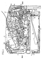
- the photosensitive member frame 46 includes a lower frame 51, and an upper frame 52, as a charger frame, that is disposed above the lower frame 51 and attached to the lower frame 51, as shown in FIG 2 .
- the lower frame 51 is integrally provided with a process accommodating portion 53 that accommodates the developing cartridge 33 and a drum accommodating portion 54 that accommodates the photosensitive drum 47 and the transfer roller 49.
- the process accommodating portion 53 is integrally provided with a bottom plate 55 that receives the developing cartridge 33, a side plate 56 that extends upwardly from each end of the bottom plate 55 in the width direction thereof perpendicular to the frontward and rearward direction.
- the process accommodating portion 53 is of substantially U shape and open upwardly.
- One of the register rollers 11 (disposed on an upper side) is rotatably supported on an underside of the bottom plate 55.
- Each side plate 56 has a developing cartridge guiding groove 57 that receives the roller shaft of the developing roller 37 protruding outwardly in the width direction of the case 34, from the case 34 of the developing cartridge 33.
- the developing cartridge guiding groove 57 has a wider opening at an upper end thereof and extends rearward to form a substantially U-shape.
- the roller shaft of the developing roller 37 is received and guided by the developing cartridge guiding grooves 57 and positioned in the rearmost portion of the developing-cartridge guiding groove 57.
- the developing cartridge 33 is accommodated in the process accommodating portion 53 in which the developing roller 37 and the photosensitive drum 47 contact each other.
- the drum accommodating portion 54 is integrally provided with a transfer roller receiver 58 that receives the transfer roller 49 and a side plate 59 that extends upwardly from each end of the transfer roller receiver 58 in the width direction thereof perpendicular to the frontward and rearward direction.
- the drum accommodating portion 54 is of substantially U shape and open upwardly.
- the side plates 56 of the process accommodating portion 53 are continuously and integrally formed with the relevant side plates 59 of the drum accommodating portion 54.
- the transfer roller receiver 58 includes front and rear guide plates 60, 61 of flat plates extending in the frontward and rearward direction, and a transfer roller accommodating portion 62 that is formed into a recess curving downwardly between the front and rear guide plates 60, 61.
- the front guide plate 60 and the rear guide plate 61 guide the sheet 3 in the neighborhood of a transfer position where the toner is transferred on the sheet 3, as will be described below.
- the transfer roller 49 is disposed in the transfer roller accommodating portion 62, along the width direction thereof.
- the transfer roller 49 is supported by the side plates 59 provided on both sides of the transfer roller accommodating portion 62, to rotate in an opposite direction to the rotating direction of the photosensitive drum 47.
- the transfer roller 49 includes a metal roller shaft covered by a roller portion formed of conductive rubber. A transfer bias is applied to the roller shaft of the transfer roller 49, to transfer the toner onto the sheet 3.
- the photosensitive drum 47 is rotatably supported between the side plates 59.
- the photosensitive drum 47 is disposed above the transfer roller 49, to face the transfer roller 49.
- the photosensitive drum 47 includes a cylindrical drum body 63 and a metal drum shaft 64 that supports the drums body 63 and provided on the center of an axis of the drum body 63.
- the drum body 63 is made of an aluminum drum and a positively chargeable photosensitive coating layer formed on a surface of the aluminum drum.
- each side plate 59 Disposed on an upper front end of each side plate 59 is a lower engagement portion 65 that engages with the upper frame 52.
- the lower engagement portion 65 is of substantially recessed shape that extends in the frontward and rearward direction and is open forwardly.
- a protrusion 66 is disposed on an upper portion of the lower engagement portion 65.
- the upper frame 52 is integrally formed with an upper plate 68 that covers an upper portion of the drum accommodating portion 54 of the lower frame 51, a rear plate 69 that extends downwardly from a rear end of the upper plate 68, a front plate 70 that extends downwardly from a front end of the upper plate 68, and side plates 131, 132, provided on each end in the width direction of the upper plate 68, the rear plate 69, and the front plate 70, perpendicular to the frontward and rearward direction.
- a pair of supporting plates 98 is disposed at some positions in the forward and rearward direction with a predetermined distance therebetween, to extend along the width direction of the upper plate 68.
- the supporting plates 98 extend downwardly from the upper plate 68.
- Disposed between the supporting plates 98 is the scorotron charger 48.
- the scorotron charger 48 is disposed above the photosensitive drum 47 with a predetermined distance therebetween, to prevent the scorotron charger 48 from contacting the photosensitive drum 47.
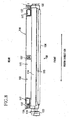
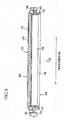
- the charger 48 is a positively charging scorotron charger. As shown in FIGS. 3 and 4 , the scorotron charger 48 includes a wire 71 that generates a corona discharge, a first fixing portion 72 and a second fixing portion 73 that fix ends of the wire 71 in a longitudinal direction of the wire 71, a grid electrode 74 disposed below the wire 71 to face the wire 71, and a wire cleaner 75 that cleans the wire 71.
- the wire 71 is a tungsten wire disposed between the supporting plates 98.
- the wire 71 is disposed with a predetermined distance between the wire 71 and the photosensitive drum 47, between the first and second fixing portions 72, 73 along the width direction of the upper frame 52, as indicated in FIGS. 3 and 4 , to face the photosensitive drum 47.
- a ring-shaped retainer 86 is disposed at each end of the wire 71 in the longitudinal direction thereof.
- the first fixing portion 72 is disposed on one side of the upper plate 68 of the upper frame 52 in the longitudinal direction of the wire 71.
- the first fixing portion 72 includes a first positioning member 76 that positions the wire 71 in a vertical direction, as a first direction (direction that the scorotron charger 48 and the photosensitive drum 47 face each other) perpendicular to the longitudinal direction of the wire 71, a second positioning member 77 that positions the wire 71 in the longitudinal direction thereof and in a horizontal (forward and rearward) direction, as a second direction, perpendicular to the vertical direction, and a supporting member 78 that supports one end of the wire 71.
- a first fixing portion supporting member 97 that extends inwardly in the width direction of the upper frame 52.
- the first positioning member 76 is disposed inwardly from the second positioning member 77 in the width direction of the upper frame 52 at a position parallel to the longitudinal direction of the wire 71.
- the first positioning member 76 is held upright at the first fixing portion supporting member 97 with a predetermined distance between the first positioning member 76 and the second positioning member 77.
- the second positioning member 77 is disposed outwardly from the first positioning member 76 in the width direction of the upper frame 52, so as to extend downwardly from the upper plate 68. With the structure, the second positioning member 77 is disposed closer to the end of the wire 71 in the longitudinal direction thereof than the first positioning member 76.
- the first positioning member 76 is of substantially "L" shape in side view.
- the first positioning member 76 is integrally formed with a first contact portion 79 where the wire 71 is positioned while contacting the first contact portion 79, and a first guide portion 80 that guides the wire 71 to the first contact portion 79.
- the first contact portion 79 is of a substantially rectangular plate shape. Formed on an upper end of the first contact portion 79 is a first contact surface 85 that positions the wire 71 in the vertical direction by contacting the wire 71 to the first contact surface 85.
- the first contact surface 85 extends levelly in the forward and rearward direction (in the horizontal direction), to prevent the wire 71 from moving in the vertical direction.
- the first contact surface 85 is chamfered to improve the accuracy of positioning the wire 71.
- the first guide portion 80 is of a substantially triangular plate shape. Formed on a rear end of the first guide portion 80 is a restriction surface 82 that is connected to a front end of the first contact surface 85. A first guide surface 81 is formed to connect an upper end of the restriction surface 82.
- the restriction surface 82 is a stepped portion formed between the first contact surface 85 and the first guide surface 81.
- the restriction surface 82 stands upright at the front end of the first contact surface 85.
- the restriction surface 82 is a flat surface extending in the vertical direction.
- the restriction surface 82 is chamfered to improve the accuracy of positioning the wire 71.
- the first guide surface 81 is a flat surface extending forwardly in an upward slanting direction from an upper end of the restriction surface 82.
- the first guide surface 81 is chamfered to smoothly guide the wire 71.
- the second positioning member 77 is a flat plate extending in the width direction of the upper frame 52 and downwardly from the upper plate 68.
- the second positioning member 77 is integrally formed with a second contact surface 83, as a second contact portion, where the wire 71 is the positioned wire 71 while contacting the second contact surface 83, and a second guide surface 84, as a second guide portion, that guides the wire 71 to the second contact surface 83.
- the second contact surface 83 is formed as a lower edge of the second positioning member 77.
- the second contact surface 83 is rounded to prevent the wire 71 contacting the contact surface 83 from being moved in the forward or rearward direction.
- the second guide surface 84 is formed as a front face of the second positioning member 77 into a flat surface connected to the second contact surface 83.
- the supporting member 78 is disposed on a rear side of the second positioning member 77.
- the supporting member 78 includes an elastic engagement member 87 that is made of a wire, and a fixing member 88 that fixes the elastic engagement member 87.
- the fixing member 88 is integrally formed with a fixing plate 89 that extends downward from one side end of the upper plate 68, an engagement shaft 90 that is disposed on an upper portion of the fixing plate 89 and protrudes outwardly in the width direction of the upper plate 52, and a fixing portion 91 that is disposed on the fixing plate 89 behind the engagement shaft 90.
- the elastic engagement member 87 is of substantially "L" shape.
- the elastic engagement member 87 is integrally formed with a ring portion 92 that is wound in a circular shape and is fitted over the engagement shaft 90, a hook 93 that is connected or hooked to the retainer 86 provided on the one end of the wire 71, and an engagement fixed portion 94 that is fixed at the fixing portion 91.
- the second fixing portion 73 is disposed on the upper plate 68 of the upper frame 52 on an opposite side from the first fixing portion 72 in the longitudinal direction of the wire 71.
- the second fixing portion 73 includes a wire engagement portion 95 that fixes the other end of the wire 71.
- the wire engagement portion 95 is of a substantially rectangular plate shape.
- the wire engagement portion 95 is provided with a slit 96 into which the other end portion of the wire 71 inserted.
- the slit 96 has such a width that allows the other end of the wire 71 to pass through the slit 96.
- the slit 96 is formed at a substantially central portion of the wire engagement portion 95 in the frontward and rearward direction, into a recessed shape that extends downwardly from an upper edge of the wire engagement portion 95.
- the deepest portion of the slit 96 is substantially at the same level as the height of the first contact surface 85 of the first positioning member 76.
- the other end of the wire 71 is inserted into the slit 96 of the wire engagement portion 95 to fixedly dispose the retainer 86 provided on the other end of the wire 71 outwardly of the wire engagement portion 96 in the width direction of the upper frame 52, as shown in FIG 7 .
- the wire 71 is guided toward a lower slanting direction, to the first contact surface 85, through the restriction surface 82.
- the wire 71 is positioned in a first contact position where the wire 71 contacts the first contact surface 85.
- the wire 71 is positioned in the vertical direction.
- the one end of the wire 71 placed outwardly in the width direction of the upper plate 52 from the first contact position.
- the one end of the wire 71 is made contact with the second guide surface 84 of the second positioning member 77. While being made contact with the second guide surface 84, the wire 71 is guided downward and then pulled rearward to contact the second contact surface 83.
- the wire 71 is positioned in the second contact position where the wire 71 contacts the second contact surface 83.
- the wire 71 is positioned in the frontward and rearward direction (horizontal direction).
- the retainer 86 provided at the one end of the wire 71 is hooked or connected to the hook 93 of the elastic engagement member 87.
- the ring portion 92 of the elastic engagement member 87 is fitted over the engagement shaft 90.
- the engagement fixed portion 94 is fixed at the fixing portion 91.
- the wire 71 is supported under tension at a position below the first contact position where the wire 71 contacts the first contact surface 85 (i.e., the wire 71 is pulled toward the first contact portion 79) and on a rear side of the second contact position where the wire 71 contacts the second contact surface 83 (i.e., the wire 71 is pulled toward the second contact surface 83).
- the wire 71 is positioned in the longitudinal direction of the wire 71.
- the grid electrode 74 is disposed between a pair of the supporting plates 98.
- the grid electrode 74 is formed of a plurality of fine wires aligned in parallel in the frontward and rearward direction with a predetermined distance between the adjacent fine wires.
- the grid electrode 74 is disposed between the wire 71 and the photosensitive drum 47.
- the wire cleaner 75 includes a wire holding portion 99 that holds the wire 71 at the front and rear sides thereof, and a holder 100 provided above the wire holding portion 99.
- the holder 100 is supported by the supporting plates 98 to allow the holder 100 to slide along the longitudinal direction of the wire 71.
- the holder 100 While the wire 71 is held by the wire holding portion 99, the holder 100 is moved from the other end side of the wire 71 (left side end in FIG 3 ) to the one end side of the wire 71 (right side end in FIG 3 ).
- the wire cleaner 75 cleans the wire 71 with the wire holding portion 99 that removes materials attached to an outer surface of the wire 71 as the holding portion 99 holding the wire 71 is moved together with the holder 100.
- a light introducing opening 101 for irradiating the photosensitive drum 47 with the laser beam from the scanner unit 20, is formed in the upper plate 68 on the front side of the scorotron charger 48, to extend along the width direction of the upper plate 68.
- each front end of the upper plate 68 in the width direction thereof is an upper engagement portion 121 that engages with the relevant lower engagement portion 65 of the lower frame 51.
- the upper engagement portion 121 is of substantially "L" shape.
- the upper engagement portion 121 is integrally formed with a vertical portion 122 that extends downwardly along the front plate 70 and a protrusion123 that extends rearward and in a downward slanting direction from a lower edge of the vertical portion 122.
- a screw attaching portion 67 that is placed over the screw fixing portion formed on the lower frame 51 is provided at each rear end of the upper plate 68 in the width direction thereof.
- the upper frame 51 is made contact with the lower frame 51 at the front side thereof. More specifically an upper surface of the protrusion123 of the upper engagement portion 121 of the upper frame 52, is made contact with a lower surface (cornered surface) of the protrusion 66 of the lower engagement portion 65 of the lower frame 51.
- the upper frame 52 is rotated about the contact portion of the protrusions 66, 123 as a pivot, so as to place the screw attaching portions 67 over the screw fixing portions formed on the lower frame 51.
- the upper frame 52 is screwed onto the upper frame 51.
- the upper surface of the protrusion123 of the upper engagement portion 121 of the upper frame 52 contacts non-parallel with the lower surface of the protrusion 66 of the lower engagement portion 65 of the lower frame 51. That is, the cornered portion of the protrusion 66 of the lower engagement portion 65 and the upper surface of the protrusion123 of the upper engagement portion 121 contact in a slanting manner.
- a rear wall of the lower frame 51 and the rear plate 69 of the upper frame 52 forms an overlapped portion 124 where the rear wall of the lower frame 51 and the rear plate 69 of the upper frame 52 overlap in the frontward and rearward direction.
- the surface of the photosensitive drum 47 is uniformly and positively charged by the scorotron charger 48 while the photosensitive drum 47 rotates. As the surface of the photosensitive drum 47 is selectively exposed to the laser beam emitted from the scanner unit 20 based on image data, an electrostatic latent image is formed on the surface of the photosensitive drum 47.
- the toner which is carried on the developing roller 37 and is positively charged, is brought into confrontation with the photosensitive drum 47 in accordance with the rotation of the developing roller 37, the toner is supplied to parts of the photosensitive drum 47 selectively exposed to the laser beam where the potential level is lower than the remaining part of the photosensitive drum 47 surface uniformly positively charged.
- the toner is selectively carried on the photosensitive drum 47, making the toner image visible.
- the sheet 3 fed by the register rollers 11 makes contact with the surface of the photosensitive drum 47.
- the toner carried on the surface of the photosensitive drum 47 is transferred on the sheet 3 when the sheet 3 passes between the photosensitive drum 47 and the transfer roller 49.
- the sheet 3 having the toner transferred thereon is fed to the fixing unit 22.
- the cleaning unit 50 is disposed on the rear end portion of the lower frame 51 to face the photosensitive drum 47.
- the cleaning unit 50 includes a lower unit frame 102, an upper unit frame 103, first and second cleaning rollers 104, 105, as a foreign material removing member and a cleaning member, and a sponge scraper 106, as a foreign material removing member and a scraping member.
- a cleaning holder plate 108 Disposed on a rear end portion of the lower frame 51 is a cleaning holder plate 108.
- the lower unit frame 102 is supported above the cleaning holder plate 108.
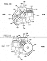
- the lower frame 102 is integrally provided with a bottom wall 109, a rear wall 110, and side walls 111, 112, as shown in FIGS. 10 and 11 .
- a partition wall 113 is provided at a position in the frontward and rearward direction to extend along the width direction perpendicular to the frontward and rearward direction.
- a front end wall 138 that protrudes upward is disposed on a front end side of the bottom plate 109 to extend in the width direction.
- the upper unit frame 103 is integrally provided with an upper wall 114, front and rear inclined walls 115, 116 that incline downwardly from front and rear of the upper wall 114, respectively, and side walls 139, 140, as shown in FIGS. 10 and 11 .
- a spring 117 as an urging member, is disposed on each end portion of the rear inclined wall 116 in the width direction thereof.
- Each spring 117 is formed of a flat spring, as shown in FIGS. 10 and 11 .
- the springs 117 are disposed to urge the first cleaning roller 104 of the cleaning unit 50 toward the photosensitive drum 47, as shown in FIG 2 .
- the upper unit frame 103 is disposed above the lower unit frame 102 to cover the lower unit frame 102. As shown in FIG 8 , the upper unit frame 103 is fixed onto the lower unit frame 102, using screws 137.
- the lower unit frame 102 and the upper unit frame 103 form a case 118 of the cleaning unit 50 that is open at the front side facing the photosensitive drum 47.
- the springs 117 are disposed between the upper frame 52 and the upper unit frame 103 and on an opposite side of the photosensitive drum 47 with respect to a facing position where the case 118 faces the photosensitive drum 47, as shown in FIG. 2 .
- a front side of the partition wall 113 is defined as a paper powder removing chamber 119, as a foreign material removing chamber, and a rear side of the partition wall 113 is defined as a paper powder reservoir 120 as a foreign material reservoir.
- the first cleaning roller 104 is rotatably supported in the side walls 111, 112 of the lower unit frame 102, such that a part of the first cleaning roller 104 is exposed from an opening of the case 118 to contact the photosensitive drum 47.
- a first cleaning roller drive gear 133 to which drive force from a motor (not shown) is input, is mounted on an end of the first cleaning roller 104 that protrudes outwardly from the side wall 111 in the width direction of the cleaning unit 50, as shown in FIG 9 .
- the first cleaning roller 104 is rotated by the drive force input to the first cleaning roller drive gear 133.
- a collar member 135 that functions as an electrode for applying a first cleaning bias to the first cleaning roller 104 is mounted on the other end of the first cleaning roller 104 that protrudes in the width direction of the cleaning unit 50 outwardly from the side wall 112.
- the first cleaning bias is applied by a power source (not shown) to the first cleaning roller 104 through the collar member 135.
- the second cleaning roller 105 is rotatably supported in the side walls 111, 112 of the lower unit frame 102, such that the second cleaning roller 105 is disposed behind the first cleaning roller 104 to contact the first cleaning roller 104.
- a second cleaning roller drive gear 134 that engages with the first cleaning roller drive gear 133 is mounted on an end of the second cleaning roller 105 that protrudes in the width direction of the cleaning unit 50 outwardly from the side wall 111. The second cleaning roller 105 is rotated by the drive force input to the second cleaning roller drive gear 134.
- a collar member 136 that functions as an electrode for applying a second cleaning bias to the second cleaning roller 105 is mounted on the other end of the second cleaning roller 105 that protrudes in the width direction of the cleaning unit 50 outwardly from the side wall 112.
- the second cleaning bias is applied by a power source (not shown) to the second cleaning roller 105 through the collar member 136.
- the sponge scraper 106 is disposed above the second cleaning roller 105 to contact the second cleaning roller 105.
- the sponge scraper 106 is supported on the upper wall 114 of the upper unit frame 103.
- the toner which remains on the photosensitive drum 47, without being transferred on the sheet 3, is collected by the cleaning unit 50. More specifically, in the cleaning unit 50, a bias (negative bias) lower than the potential of the photosensitive drum 47 surface is applied to the first cleaning roller 104 when opposing the portion of the photosensitive drum 47 carrying the toner that was to be transferred onto the sheet 3 but remains on the photosensitive drum 47, to temporarily catch the toner remaining on the photosensitive drum 47.
- a bias (negative bias) lower than the potential of the photosensitive drum 47 surface is applied to the first cleaning roller 104 when opposing the portion of the photosensitive drum 47 carrying the toner that was to be transferred onto the sheet 3 but remains on the photosensitive drum 47, to temporarily catch the toner remaining on the photosensitive drum 47.
- a bias (positive bis) higher than the potential of the photosensitive drum 47 surface is applied to the first cleaning roller 104 when opposing the portion of the photosensitive drum 47 that does not carry the toner for transfer onto the sheet 3, that is, when a part of the photosensitive drum 47 corresponding to an interval between two successive sheets 3 contacts the first cleaning roller 104, in order to return the toner temporarily caught by the first cleaning roller 104 to the photosensitive drum 47. Paper powders attached by the sheet 3 to the photosensitive drum 47 when the toner is transferred on the sheet 3 are caught by the first cleaning roller 104. The toner returned to the photosensitive drum 47 is collected by the developing roller 37.
- the paper powders caught by the first cleaning roller 104 are then electrically caught by the second cleaning roller 105 when the first cleaning roller 104 is brought into confrontation with the second cleaning roller 105.
- the paper powders.caught by then second cleaning roller 105 are scraped by the sponge scraper 106, when opposing the sponge scraper 106, and stored in the paper powder reservoir 120.
- the residual toner and the paper powders on the photosensitive drum 47 are electrically attracted to the first cleaning roller 104.
- the toner attracted to the first cleaning roller 104 is electrically returned to the photosensitive drum 47.
- the paper powders attracted to the first cleaning roller 104 is electrically attracted to the second cleaning roller 105 and caught by the second cleaning roller 105.
- the paper powders are effectively removed concurrently with the residual toner collection in a cleaner-less system.
- the fixing unit 22 is positioned downstream of the process unit 21 in the sheet feeding direction behind the process unit 21.
- the fixing unit 22 includes a heat roller 125, a pressure roller 126 and feed rollers 127.
- the heat roller 125 includes a metal tube accommodating a halogen lamp as a heat source.
- the pressure roller 126 is disposed below the heat roller 125 to press the heat roller 125 from below.
- the feed rollers 127 are disposed downstream of the heat roller 125 and the pressure roller 126 in the sheet feeding direction.
- the toner transferred onto the sheet 3 is thermally fixed to the sheet 3 while the sheet 3 passes through between the heat roller 125 and the pressure roller 126.
- the sheet 3 is guided by the feed rollers 127 to a guide plate 128 vertically disposed behind the feed rollers 125. Then, the sheet 3 is fed toward discharge rollers 129.
- the sheet 3 fed to the discharge rollers129 is discharged onto a discharge tray 130.
- the wire 71 is vertically and horizontally positioned by the first positioning member 76 and the second positioning member 77, respectively, at the first fixing portion 72.
- the positioning accuracy required for each first and second positioning member 76, 77 is only the accuracy in a vertical direction and a horizontal direction, respectively. Therefore, as compared with a case where the wire 71 is positioned by a single positioning member, the positioning accuracy required for each positioning member 76, 77 may be reduced. Accordingly, the first and second positioning members 76, 77 are formed with a simple structure and with sufficient strength.
- the first positioning member 76 positions the wire 71 in the vertical direction.
- the second positioning member 77 positions the wire 71 in the horizontal direction.
- the wire 71 is positioned by the first positioning member 76 and the second positioning member 77 that are disposed with a predetermined distance therebetween in the longitudinal direction of the wire 71. Therefore, the positioning accuracy of the wire 71 is improved.
- the wire 71 is disposed with a predetermined distance between the wire 71 and the photosensitive drum 47, so that the photosensitive drum 47 is uniformly charged.
- the wire 71 is first positioned in the vertical direction by the first positioning member 76 and then in the horizontal direction by the second positioning member 77 disposed outward of the first positioning member 76 in the longitudinal direction of the wire 71.
- the positioning of the wire 71 with the first positioning member 76 in the vertical direction in which the scorotron charger 48 and the photosensitive drum 47 face each other takes precedence over the positioning of the wire 71 in the horizontal direction. Accordingly, the photosensitive drum 47 is uniformly charged by the scorotron charger 48.
- the wire 71 is supported under tension at a position below the first contact position where the wire 71 contacts the first contact surface 85 (i.e., the wire 71 is pulled toward the first contact portion 79) and on a rear side of the second contact position where the wire 71 contacts the second contact surface 83 (i.e., the wire 71 is pulled toward the second contact surface 83).
- the wire 71 is properly positioned by the first and second positioning members 76, 77, and supported by the supporting member 78 while the wire 71 is positioned in the longitudinal direction thereof.
- the wire 71 is guided toward a lower slanting direction, to the first contact surface 85, through the restriction surface 82.
- the wire 71 is vertically positioned.
- the one end of the wire 71 placed outwardly in the width direction of the upper plate 52 from the position where the wire 71 is positioned by the first positioning member 76.
- the one end of the wire 71 is made contact with the second guide surface 84 of the second positioning member 77. While being made contact with the second guide surface 84, the wire 71 is guided downward and then pulled rearward to contact the second contact surface 83.
- the wire 71 is positioned in the horizontal direction.
- the deepest portion of the slit 96 is at substantially the same level as the height of the first contact surface 85 of the first positioning member 76. Therefore, the other end of the wire 71 and the one end of the wire 71 positioned by the first positioning member 76 are positioned substantially at the same level or height. Thus, the accuracy of positioning the wire 71 over the length of the wire 71 is improved.
- the photosensitive drum 47 is supported in the lower frame 51.
- the scorotron charger 48 is supported in the upper frame 52. With the lower and upper frames 51, 52 assembled together, the scorotron charger 48 is positioned relative to the photosensitive drum 47.
- each spring 117 urges the first cleaning roller 104 of the cleaning unit 50 toward the photosensitive drum 47. Therefore, regardless of the mounting accuracy of the cleaning unit 50, the first cleaning roller 104 uniformly contacts the photosensitive drum 47. Even if the position of the cleaning unit 50 relative to the photosensitive drum 47 is deviated every time then cleaning unit 50 is set in the photosensitive member cartridge 32, performances of removing the paper powders is stable. The cleaning unit 50 is urged toward the photosensitive drum 47 with a simple structure using the springs 117.
- Each spring 117 urges the cleaning unit 50 toward the photosensitive drum 47 from each end in the width direction of the rear inclined wall 116, that is, each end of the cleaning unit 50 in the axial direction of the photosensitive drum 47.
- the first cleaning roller 104 uniformly contacts the photosensitive drum 47 along the longitudinal direction of the photosensitive drum 47.
- the springs 117 are disposed on the rear inclined wall 116 of the upper unit frame 103. Due to the inclination of the wall 116, the urging forces of the springs 117 are directed toward the photosensitive drum 47. Thus, the springs 117 reliably urge the cleaning unit 50 and the first cleaning roller 104 is reliably urged toward the photosensitive drum 47.
- Each spring 117 urges the cleaning unit 50 that faces the photosensitive drum 47 from the opposite side of the photosensitive drum 47 with respect to a position where the cleaning unit 50 faces the photosensitive drum 47. Accordingly, the reliable contact of the first cleaning roller 104 to the photosensitive drum 47 is made.
- Each spring 117 is disposed between the upper frame 52 and the cleaning unit 50, so that the first cleaning roller 104 is reliably urged toward the photosensitive drum 47.
- the cleaning unit 50 is supported by the cleaning holder plate 108 of the lower frame 51.
- the cleaning unit 50 which is disposed in the lower frame 51, is urged by each spring 117 disposed between the upper frame 52 and the cleaning unit 50. Accordingly, the first cleaning roller 104 is reliably made contact with the photosensitive drum 47.
- the cleaning unit 50 paper powders on the photosensitive drum 47 are removed by the first cleaning roller 104. Thereafter, the paper powders caught by the first cleaning roller 104 are caught by the second cleaning roller 105. The paper powders caught by the second cleaning roller 105 are then removed by the sponge scraper 106. As the paper powders caught by the first and second cleaning rollers 104, 105 are removed by the sponge scraper 106, the paper powders are not left in either the first or second cleaning roller 104, 105. Thus, the paper powder removal efficiency may be maintained for a long period of time.
- the first and second cleaning rollers 104, 105 are disposed in the lower unit frame 102, and the sponge scraper 106 is disposed in the upper unit frame 103.
- the sponge scraper 106 is positioned relative to the first and second cleaning rollers 104, 105.
- the paper powder removing chamber 119 and the paper powder reservoir 120 are separated from each other in the case 118.
- the paper powders removed in the paper powder removing chamber 119 are stored in the paper powder reservoir 120.
- paper powders are prevented from being released or scattered, as well as being attached again to the first or second cleaning roller 104, 105. Accordingly, the paper removing efficiency is improved.
- the cleaning unit 50 is open on a side of the paper powder removing chamber 119 facing the photosensitive drum 47.
- the first cleaning roller 104 is exposed from the opening through which the first cleaning roller 104 contacts the photosensitive drum 47. Therefore, the paper powders on the photosensitive drum 47 are reliably removed.
- a charger frame, a photosensitive member cartridge including the charger frame, and an image forming apparatus including the photosensitive member cartridge according to the invention may be applied to various types of image forming apparatuses.
Landscapes
- Physics & Mathematics (AREA)
- Engineering & Computer Science (AREA)
- General Physics & Mathematics (AREA)
- Plasma & Fusion (AREA)
- Computer Vision & Pattern Recognition (AREA)
- Electrostatic Charge, Transfer And Separation In Electrography (AREA)
- Electrophotography Configuration And Component (AREA)
Claims (11)
- Dispositif de charge (48), comportant :un fil (71) qui génère une décharge à effet de couronne ;un châssis de dispositif de charge (52) qui supporte le fil (71) ; etune première partie de fixation (72) qui assure la fixation d'au moins une extrémité du fil (71) suivant une première direction qui est une direction longitudinale du fil (71), la première partie de fixation (72) étant disposée sur le châssis de dispositif de charge (52) ;dans lequel la première partie de fixation (72) comporte un premier élément de positionnement (76) qui vient en contact avec le fil (71) à une première position de contact afin de positionner ainsi le fil (71) suivant une deuxième direction perpendiculaire à la première direction, etdans lequel la première partie de fixation (72) comporte en outre un second élément de positionnement (77),caractérisé en ce que :le second élément de positionnement (77) est configuré de manière à venir en contact avec le fil (71) à une seconde position de contact afin de positionner ainsi le fil (71) suivant la première direction et suivant une troisième direction perpendiculaire à la deuxième direction,le premier élément de positionnement (76) et le second élément de positionnement (77) sont disposés avec une certaine distance prédéterminée entre eux suivant une direction parallèle à la première direction, etla première partie de fixation (72) comporte en outre un élément de support (78, 87) dans lequel la ou les extrémités du fil (71) sont tendues vers un côté du premier élément de positionnement (76) et vers un côté du second élément de positionnement (77).
- Dispositif de charge selon la revendication 1, dans lequel l'élément de support (78, 87) est configuré de manière à supporter la ou les extrémités du fil (71) à une hauteur différente d'une hauteur du fil au niveau de la première position de contact.
- Dispositif de charge selon la revendication 1 ou 2, dans lequel le premier élément de positionnement (76) comporte une première partie de contact (79) qui vient en contact avec le fil (71), et une première partie de guidage (80) qui guide le fil (71) vers la première partie de contact (79), le fil (71) étant positionné au niveau de la première partie de contact (79).
- Dispositif de charge selon l'une quelconque des revendications 1 à 3, dans lequel le second élément de positionnement (77) comporte une seconde partie de contact (83) qui vient en contact avec le fil, et une seconde partie de guidage (84) qui guide le fil vers la seconde partie de contact (83), le fil (71) étant positionné au niveau de la seconde partie de contact (83).
- Dispositif de charge selon l'une quelconque des revendications 1 à 4, comprenant en outre une seconde partie de fixation (73) qui assure la fixation d'une autre extrémité du fil (71) suivant la première direction, dans lequel la seconde partie de fixation (73) assure la fixation de l'autre extrémité du fil (71) à une hauteur sensiblement identique à la hauteur du fil positionné au niveau de la première partie de fixation (72) suivant la deuxième direction par le premier élément de positionnement (76).
- Dispositif de charge selon l'une quelconque des revendications 1 à 5, dans lequel la deuxième direction est une direction verticale et la troisième direction est une direction horizontale.
- Cartouche d'élément photosensible (32), comprenant :un dispositif de charge (48) selon l'une quelconque des revendications 1 à 6 ;un élément photosensible (47) ;un châssis d'élément photosensible (46) qui comporte un châssis supérieur pour le châssis de dispositif de charge (52) et un châssis inférieur (51) qui supporte l'élément photosensible (47).
- Cartouche d'élément photosensible selon la revendication 7, dans laquelle le fil (71) est disposé avec une certaine distance prédéterminée entre le fil (71) et l'élément photosensible (47).
- Cartouche d'élément photosensible selon la revendication 7 ou 8, dans laquelle une direction, suivant laquelle le dispositif de charge et l'élément photosensible (47) sont l'un face à l'autre, est la deuxième direction.
- Cartouche d'élément photosensible selon la revendication 9, dans laquelle le second élément de positionnement (77) est positionné plus près de la ou des extrémités du fil (71), suivant la direction longitudinale de celui-ci, que le premier élément de positionnement (76).
- Dispositif de formation d'image (1), comprenant :une cartouche d'élément photosensible (32) selon l'une quelconque des revendications 7 à 10, dans lequel la cartouche d'élément photosensible (32) est un ensemble amovible sur le dispositif de formation d'image.
Applications Claiming Priority (4)
| Application Number | Priority Date | Filing Date | Title |
|---|---|---|---|
| JP2003288154A JP4366633B2 (ja) | 2003-08-06 | 2003-08-06 | 帯電器フレーム、感光体カートリッジおよび画像形成装置 |
| JP2003288155 | 2003-08-06 | ||
| JP2003288154 | 2003-08-06 | ||
| JP2003288155A JP4389153B2 (ja) | 2003-08-06 | 2003-08-06 | 感光体カートリッジおよび画像形成装置 |
Publications (3)
| Publication Number | Publication Date |
|---|---|
| EP1505457A2 EP1505457A2 (fr) | 2005-02-09 |
| EP1505457A3 EP1505457A3 (fr) | 2006-05-03 |
| EP1505457B1 true EP1505457B1 (fr) | 2014-12-17 |
Family
ID=33554531
Family Applications (1)
| Application Number | Title | Priority Date | Filing Date |
|---|---|---|---|
| EP04018500.1A Expired - Lifetime EP1505457B1 (fr) | 2003-08-06 | 2004-08-04 | Frame de chargement, cartouche d'un membre photosensible et appareil de formation d'images |
Country Status (4)
| Country | Link |
|---|---|
| US (1) | US7236719B2 (fr) |
| EP (1) | EP1505457B1 (fr) |
| KR (1) | KR101062505B1 (fr) |
| CN (1) | CN100399208C (fr) |
Families Citing this family (9)
| Publication number | Priority date | Publication date | Assignee | Title |
|---|---|---|---|---|
| USD507295S1 (en) * | 2003-08-12 | 2005-07-12 | Brother Industries, Ltd. | Photosensitive drum unit |
| TWD103788S1 (zh) * | 2003-08-12 | 2005-03-21 | 兄弟工業股份有限公司 | 感光鼓單元 |
| USD521545S1 (en) * | 2004-08-13 | 2006-05-23 | Brother Industries, Ltd. | Photosensitive drum unit |
| USD523896S1 (en) * | 2004-08-13 | 2006-06-27 | Brother Industries, Ltd. | Photosensitive drum unit |
| AU303120S (en) * | 2004-10-21 | 2005-09-14 | Brother Ind Ltd | Photosensitive drum unit |
| US7618404B2 (en) * | 2005-06-23 | 2009-11-17 | The Procter & Gamble Company | Disposable absorbent article having doubled side flaps and backsheet strips |
| JP4596062B2 (ja) * | 2008-09-29 | 2010-12-08 | ブラザー工業株式会社 | 帯電ワイヤの取付方法、プロセスカートリッジの製造方法およびプロセスカートリッジ |
| JP5471020B2 (ja) * | 2009-05-01 | 2014-04-16 | ブラザー工業株式会社 | 感光体ユニットおよびタンデム型感光体ユニット |
| JP5333470B2 (ja) | 2011-01-28 | 2013-11-06 | ブラザー工業株式会社 | クリーニング装置 |
Citations (1)
| Publication number | Priority date | Publication date | Assignee | Title |
|---|---|---|---|---|
| JP2000267470A (ja) * | 1999-03-18 | 2000-09-29 | Copyer Co Ltd | コロナ転写帯電装置 |
Family Cites Families (16)
| Publication number | Priority date | Publication date | Assignee | Title |
|---|---|---|---|---|
| US4575221A (en) * | 1982-05-20 | 1986-03-11 | Canon Kabushiki Kaisha | Process kit and an image forming apparatus using the same |
| GB2132942B (en) * | 1982-09-30 | 1987-07-29 | Canon Kk | Detachable parts of image-forming apparatus |
| US4754305A (en) * | 1983-11-02 | 1988-06-28 | Xerox Corporation | Corona discharge device |
| US4551784A (en) * | 1984-06-29 | 1985-11-05 | Xerox Corporation | Corona generating device |
| JPS6276350U (fr) * | 1985-10-30 | 1987-05-15 | ||
| JPH046030Y2 (fr) * | 1986-05-16 | 1992-02-19 | ||
| JPS63226669A (ja) * | 1986-10-08 | 1988-09-21 | Nec Corp | 画像形成装置 |
| US4866482A (en) * | 1986-10-24 | 1989-09-12 | Ricoh Company, Ltd. | Image forming device for electrostatic recording apparatus having a slidable replacement holding case |
| US5258816A (en) * | 1990-01-26 | 1993-11-02 | Konica Corporation | Cleaning device for a color image forming apparatus |
| US5216465A (en) * | 1990-03-19 | 1993-06-01 | Fuji Xerox Co., Ltd. | Print cartridge insertable into an image forming apparatus |
| JPH07140754A (ja) | 1993-11-18 | 1995-06-02 | Canon Inc | 帯電器及び画像形成装置 |
| JPH07319362A (ja) * | 1994-05-19 | 1995-12-08 | Canon Inc | プロセスカートリッジの再生産方法及びプロセスカートリッジ |
| US6144826A (en) * | 1996-11-25 | 2000-11-07 | Xerox Corporation | Insert for mounting wires to corotron frames |
| JP3383745B2 (ja) * | 1997-01-18 | 2003-03-04 | 京セラミタ株式会社 | クリーニング装置の押圧機構 |
| JPH11161126A (ja) | 1997-11-27 | 1999-06-18 | Konica Corp | 画像形成装置 |
| JP4366633B2 (ja) * | 2003-08-06 | 2009-11-18 | ブラザー工業株式会社 | 帯電器フレーム、感光体カートリッジおよび画像形成装置 |
-
2004
- 2004-08-04 EP EP04018500.1A patent/EP1505457B1/fr not_active Expired - Lifetime
- 2004-08-04 US US10/910,326 patent/US7236719B2/en not_active Expired - Lifetime
- 2004-08-05 KR KR1020040061546A patent/KR101062505B1/ko not_active Expired - Fee Related
- 2004-08-06 CN CNB2004100564176A patent/CN100399208C/zh not_active Expired - Lifetime
Patent Citations (1)
| Publication number | Priority date | Publication date | Assignee | Title |
|---|---|---|---|---|
| JP2000267470A (ja) * | 1999-03-18 | 2000-09-29 | Copyer Co Ltd | コロナ転写帯電装置 |
Also Published As
| Publication number | Publication date |
|---|---|
| CN1580973A (zh) | 2005-02-16 |
| US20050031373A1 (en) | 2005-02-10 |
| EP1505457A2 (fr) | 2005-02-09 |
| EP1505457A3 (fr) | 2006-05-03 |
| KR101062505B1 (ko) | 2011-09-05 |
| CN100399208C (zh) | 2008-07-02 |
| US7236719B2 (en) | 2007-06-26 |
| KR20050016151A (ko) | 2005-02-21 |
Similar Documents
| Publication | Publication Date | Title |
|---|---|---|
| US7116919B2 (en) | Developing cartridge, process unit, and image forming apparatus | |
| US6415119B2 (en) | Paper powder collector, process cartridge and image forming apparatus | |
| CN100442156C (zh) | 处理盒和成像装置 | |
| US8078083B2 (en) | Image forming apparatus in which developing unit is easily detachable to photosensitive member unit | |
| EP1505457B1 (fr) | Frame de chargement, cartouche d'un membre photosensible et appareil de formation d'images | |
| KR100983444B1 (ko) | 프로세스 장치, 감광 본체 카트리지, 감광 본체 카트리지조립 방법 및 화상 형성 장치 | |
| US6920297B2 (en) | Image forming apparatus that cleans a wire of a charger | |
| JP4586620B2 (ja) | 現像カートリッジ、プロセスカートリッジおよび画像形成装置 | |
| US7570891B2 (en) | Developing cartridge, image carrier cartridge, process cartridge, and image forming apparatus | |
| EP1710634A2 (fr) | Cartouche de traitement, cartouche de révélateur et dispositif de formation dýimages | |
| JP4389153B2 (ja) | 感光体カートリッジおよび画像形成装置 | |
| US7212769B2 (en) | Process cartridge and image forming apparatus | |
| JP4366633B2 (ja) | 帯電器フレーム、感光体カートリッジおよび画像形成装置 | |
| JP2005024811A (ja) | 現像カートリッジ | |
| US7532840B2 (en) | Process cartridge and image forming apparatus | |
| US7697880B2 (en) | Process cartridge and image-forming device with brush holder member | |
| JP2006308882A (ja) | プロセスカートリッジおよび、画像形成装置 |
Legal Events
| Date | Code | Title | Description |
|---|---|---|---|
| PUAI | Public reference made under article 153(3) epc to a published international application that has entered the european phase |
Free format text: ORIGINAL CODE: 0009012 |
|
| AK | Designated contracting states |
Kind code of ref document: A2 Designated state(s): AT BE BG CH CY CZ DE DK EE ES FI FR GB GR HU IE IT LI LU MC NL PL PT RO SE SI SK TR |
|
| AX | Request for extension of the european patent |
Extension state: AL HR LT LV MK |
|
| 17P | Request for examination filed |
Effective date: 20060112 |
|
| PUAL | Search report despatched |
Free format text: ORIGINAL CODE: 0009013 |
|
| AK | Designated contracting states |
Kind code of ref document: A3 Designated state(s): AT BE BG CH CY CZ DE DK EE ES FI FR GB GR HU IE IT LI LU MC NL PL PT RO SE SI SK TR |
|
| AX | Request for extension of the european patent |
Extension state: AL HR LT LV MK |
|
| AKX | Designation fees paid |
Designated state(s): AT BE BG CH CY CZ DE DK EE ES FI FR GB GR HU IE IT LI LU MC NL PL PT RO SE SI SK TR |
|
| 17Q | First examination report despatched |
Effective date: 20070221 |
|
| REG | Reference to a national code |
Ref country code: DE Ref legal event code: R079 Ref document number: 602004046324 Country of ref document: DE Free format text: PREVIOUS MAIN CLASS: G03G0021000000 Ipc: G03G0021180000 |
|
| GRAP | Despatch of communication of intention to grant a patent |
Free format text: ORIGINAL CODE: EPIDOSNIGR1 |
|
| RIC1 | Information provided on ipc code assigned before grant |
Ipc: G03G 15/02 20060101ALI20131125BHEP Ipc: G03G 21/18 20060101AFI20131125BHEP |
|
| INTG | Intention to grant announced |
Effective date: 20131210 |
|
| GRAS | Grant fee paid |
Free format text: ORIGINAL CODE: EPIDOSNIGR3 |
|
| GRAP | Despatch of communication of intention to grant a patent |
Free format text: ORIGINAL CODE: EPIDOSNIGR1 |
|
| INTG | Intention to grant announced |
Effective date: 20140627 |
|
| GRAP | Despatch of communication of intention to grant a patent |
Free format text: ORIGINAL CODE: EPIDOSNIGR1 |
|
| GRAA | (expected) grant |
Free format text: ORIGINAL CODE: 0009210 |
|
| INTG | Intention to grant announced |
Effective date: 20141031 |
|
| AK | Designated contracting states |
Kind code of ref document: B1 Designated state(s): AT BE BG CH CY CZ DE DK EE ES FI FR GB GR HU IE IT LI LU MC NL PL PT RO SE SI SK TR |
|
| REG | Reference to a national code |
Ref country code: GB Ref legal event code: FG4D |
|
| REG | Reference to a national code |
Ref country code: CH Ref legal event code: EP |
|
| REG | Reference to a national code |
Ref country code: IE Ref legal event code: FG4D |
|
| REG | Reference to a national code |
Ref country code: AT Ref legal event code: REF Ref document number: 702317 Country of ref document: AT Kind code of ref document: T Effective date: 20150115 |
|
| REG | Reference to a national code |
Ref country code: DE Ref legal event code: R096 Ref document number: 602004046324 Country of ref document: DE Effective date: 20150129 |
|
| PG25 | Lapsed in a contracting state [announced via postgrant information from national office to epo] |
Ref country code: FI Free format text: LAPSE BECAUSE OF FAILURE TO SUBMIT A TRANSLATION OF THE DESCRIPTION OR TO PAY THE FEE WITHIN THE PRESCRIBED TIME-LIMIT Effective date: 20141217 |
|
| PG25 | Lapsed in a contracting state [announced via postgrant information from national office to epo] |
Ref country code: SE Free format text: LAPSE BECAUSE OF FAILURE TO SUBMIT A TRANSLATION OF THE DESCRIPTION OR TO PAY THE FEE WITHIN THE PRESCRIBED TIME-LIMIT Effective date: 20141217 Ref country code: GR Free format text: LAPSE BECAUSE OF FAILURE TO SUBMIT A TRANSLATION OF THE DESCRIPTION OR TO PAY THE FEE WITHIN THE PRESCRIBED TIME-LIMIT Effective date: 20150318 |
|
| REG | Reference to a national code |
Ref country code: AT Ref legal event code: MK05 Ref document number: 702317 Country of ref document: AT Kind code of ref document: T Effective date: 20141217 |
|
| PG25 | Lapsed in a contracting state [announced via postgrant information from national office to epo] |
Ref country code: NL Free format text: LAPSE BECAUSE OF FAILURE TO SUBMIT A TRANSLATION OF THE DESCRIPTION OR TO PAY THE FEE WITHIN THE PRESCRIBED TIME-LIMIT Effective date: 20141217 |
|
| PG25 | Lapsed in a contracting state [announced via postgrant information from national office to epo] |
Ref country code: CZ Free format text: LAPSE BECAUSE OF FAILURE TO SUBMIT A TRANSLATION OF THE DESCRIPTION OR TO PAY THE FEE WITHIN THE PRESCRIBED TIME-LIMIT Effective date: 20141217 Ref country code: ES Free format text: LAPSE BECAUSE OF FAILURE TO SUBMIT A TRANSLATION OF THE DESCRIPTION OR TO PAY THE FEE WITHIN THE PRESCRIBED TIME-LIMIT Effective date: 20141217 Ref country code: EE Free format text: LAPSE BECAUSE OF FAILURE TO SUBMIT A TRANSLATION OF THE DESCRIPTION OR TO PAY THE FEE WITHIN THE PRESCRIBED TIME-LIMIT Effective date: 20141217 Ref country code: RO Free format text: LAPSE BECAUSE OF FAILURE TO SUBMIT A TRANSLATION OF THE DESCRIPTION OR TO PAY THE FEE WITHIN THE PRESCRIBED TIME-LIMIT Effective date: 20141217 Ref country code: SK Free format text: LAPSE BECAUSE OF FAILURE TO SUBMIT A TRANSLATION OF THE DESCRIPTION OR TO PAY THE FEE WITHIN THE PRESCRIBED TIME-LIMIT Effective date: 20141217 Ref country code: PT Free format text: LAPSE BECAUSE OF FAILURE TO SUBMIT A TRANSLATION OF THE DESCRIPTION OR TO PAY THE FEE WITHIN THE PRESCRIBED TIME-LIMIT Effective date: 20150417 |
|
| PG25 | Lapsed in a contracting state [announced via postgrant information from national office to epo] |
Ref country code: PL Free format text: LAPSE BECAUSE OF FAILURE TO SUBMIT A TRANSLATION OF THE DESCRIPTION OR TO PAY THE FEE WITHIN THE PRESCRIBED TIME-LIMIT Effective date: 20141217 Ref country code: AT Free format text: LAPSE BECAUSE OF FAILURE TO SUBMIT A TRANSLATION OF THE DESCRIPTION OR TO PAY THE FEE WITHIN THE PRESCRIBED TIME-LIMIT Effective date: 20141217 |
|
| REG | Reference to a national code |
Ref country code: DE Ref legal event code: R097 Ref document number: 602004046324 Country of ref document: DE |
|
| PLBE | No opposition filed within time limit |
Free format text: ORIGINAL CODE: 0009261 |
|
| STAA | Information on the status of an ep patent application or granted ep patent |
Free format text: STATUS: NO OPPOSITION FILED WITHIN TIME LIMIT |
|
| PG25 | Lapsed in a contracting state [announced via postgrant information from national office to epo] |
Ref country code: DK Free format text: LAPSE BECAUSE OF FAILURE TO SUBMIT A TRANSLATION OF THE DESCRIPTION OR TO PAY THE FEE WITHIN THE PRESCRIBED TIME-LIMIT Effective date: 20141217 |
|
| 26N | No opposition filed |
Effective date: 20150918 |
|
| PG25 | Lapsed in a contracting state [announced via postgrant information from national office to epo] |
Ref country code: IT Free format text: LAPSE BECAUSE OF FAILURE TO SUBMIT A TRANSLATION OF THE DESCRIPTION OR TO PAY THE FEE WITHIN THE PRESCRIBED TIME-LIMIT Effective date: 20141217 |
|
| PG25 | Lapsed in a contracting state [announced via postgrant information from national office to epo] |
Ref country code: SI Free format text: LAPSE BECAUSE OF FAILURE TO SUBMIT A TRANSLATION OF THE DESCRIPTION OR TO PAY THE FEE WITHIN THE PRESCRIBED TIME-LIMIT Effective date: 20141217 |
|
| PG25 | Lapsed in a contracting state [announced via postgrant information from national office to epo] |
Ref country code: MC Free format text: LAPSE BECAUSE OF FAILURE TO SUBMIT A TRANSLATION OF THE DESCRIPTION OR TO PAY THE FEE WITHIN THE PRESCRIBED TIME-LIMIT Effective date: 20141217 Ref country code: LU Free format text: LAPSE BECAUSE OF FAILURE TO SUBMIT A TRANSLATION OF THE DESCRIPTION OR TO PAY THE FEE WITHIN THE PRESCRIBED TIME-LIMIT Effective date: 20150804 |
|
| REG | Reference to a national code |
Ref country code: CH Ref legal event code: PL |
|
| PG25 | Lapsed in a contracting state [announced via postgrant information from national office to epo] |
Ref country code: LI Free format text: LAPSE BECAUSE OF NON-PAYMENT OF DUE FEES Effective date: 20150831 Ref country code: CH Free format text: LAPSE BECAUSE OF NON-PAYMENT OF DUE FEES Effective date: 20150831 |
|
| PG25 | Lapsed in a contracting state [announced via postgrant information from national office to epo] |
Ref country code: BE Free format text: LAPSE BECAUSE OF FAILURE TO SUBMIT A TRANSLATION OF THE DESCRIPTION OR TO PAY THE FEE WITHIN THE PRESCRIBED TIME-LIMIT Effective date: 20141217 |
|
| REG | Reference to a national code |
Ref country code: IE Ref legal event code: MM4A |
|
| REG | Reference to a national code |
Ref country code: FR Ref legal event code: PLFP Year of fee payment: 13 |
|
| PG25 | Lapsed in a contracting state [announced via postgrant information from national office to epo] |
Ref country code: IE Free format text: LAPSE BECAUSE OF NON-PAYMENT OF DUE FEES Effective date: 20150804 |
|
| PG25 | Lapsed in a contracting state [announced via postgrant information from national office to epo] |
Ref country code: HU Free format text: LAPSE BECAUSE OF FAILURE TO SUBMIT A TRANSLATION OF THE DESCRIPTION OR TO PAY THE FEE WITHIN THE PRESCRIBED TIME-LIMIT; INVALID AB INITIO Effective date: 20040804 Ref country code: BG Free format text: LAPSE BECAUSE OF FAILURE TO SUBMIT A TRANSLATION OF THE DESCRIPTION OR TO PAY THE FEE WITHIN THE PRESCRIBED TIME-LIMIT Effective date: 20141217 |
|
| PG25 | Lapsed in a contracting state [announced via postgrant information from national office to epo] |
Ref country code: CY Free format text: LAPSE BECAUSE OF FAILURE TO SUBMIT A TRANSLATION OF THE DESCRIPTION OR TO PAY THE FEE WITHIN THE PRESCRIBED TIME-LIMIT Effective date: 20141217 |
|
| REG | Reference to a national code |
Ref country code: FR Ref legal event code: PLFP Year of fee payment: 14 |
|
| PG25 | Lapsed in a contracting state [announced via postgrant information from national office to epo] |
Ref country code: TR Free format text: LAPSE BECAUSE OF FAILURE TO SUBMIT A TRANSLATION OF THE DESCRIPTION OR TO PAY THE FEE WITHIN THE PRESCRIBED TIME-LIMIT Effective date: 20141217 |
|
| REG | Reference to a national code |
Ref country code: FR Ref legal event code: PLFP Year of fee payment: 15 |
|
| PGFP | Annual fee paid to national office [announced via postgrant information from national office to epo] |
Ref country code: GB Payment date: 20220726 Year of fee payment: 19 |
|
| PGFP | Annual fee paid to national office [announced via postgrant information from national office to epo] |
Ref country code: FR Payment date: 20220713 Year of fee payment: 19 |
|
| PGFP | Annual fee paid to national office [announced via postgrant information from national office to epo] |
Ref country code: DE Payment date: 20230711 Year of fee payment: 20 |
|
| GBPC | Gb: european patent ceased through non-payment of renewal fee |
Effective date: 20230804 |
|
| PG25 | Lapsed in a contracting state [announced via postgrant information from national office to epo] |
Ref country code: GB Free format text: LAPSE BECAUSE OF NON-PAYMENT OF DUE FEES Effective date: 20230804 |
|
| PG25 | Lapsed in a contracting state [announced via postgrant information from national office to epo] |
Ref country code: GB Free format text: LAPSE BECAUSE OF NON-PAYMENT OF DUE FEES Effective date: 20230804 Ref country code: FR Free format text: LAPSE BECAUSE OF NON-PAYMENT OF DUE FEES Effective date: 20230831 |
|
| REG | Reference to a national code |
Ref country code: DE Ref legal event code: R071 Ref document number: 602004046324 Country of ref document: DE |