EP1505468A2 - Baueinheit - Google Patents
Baueinheit Download PDFInfo
- Publication number
- EP1505468A2 EP1505468A2 EP04024698A EP04024698A EP1505468A2 EP 1505468 A2 EP1505468 A2 EP 1505468A2 EP 04024698 A EP04024698 A EP 04024698A EP 04024698 A EP04024698 A EP 04024698A EP 1505468 A2 EP1505468 A2 EP 1505468A2
- Authority
- EP
- European Patent Office
- Prior art keywords
- control
- pump
- shaft
- control rod
- baueiheit
- Prior art date
- Legal status (The legal status is an assumption and is not a legal conclusion. Google has not performed a legal analysis and makes no representation as to the accuracy of the status listed.)
- Granted
Links
Images


Classifications
-
- F—MECHANICAL ENGINEERING; LIGHTING; HEATING; WEAPONS; BLASTING
- F15—FLUID-PRESSURE ACTUATORS; HYDRAULICS OR PNEUMATICS IN GENERAL
- F15B—SYSTEMS ACTING BY MEANS OF FLUIDS IN GENERAL; FLUID-PRESSURE ACTUATORS, e.g. SERVOMOTORS; DETAILS OF FLUID-PRESSURE SYSTEMS, NOT OTHERWISE PROVIDED FOR
- F15B15/00—Fluid-actuated devices for displacing a member from one position to another; Gearing associated therewith
- F15B15/18—Combined units comprising both motor and pump
-
- F—MECHANICAL ENGINEERING; LIGHTING; HEATING; WEAPONS; BLASTING
- F15—FLUID-PRESSURE ACTUATORS; HYDRAULICS OR PNEUMATICS IN GENERAL
- F15B—SYSTEMS ACTING BY MEANS OF FLUIDS IN GENERAL; FLUID-PRESSURE ACTUATORS, e.g. SERVOMOTORS; DETAILS OF FLUID-PRESSURE SYSTEMS, NOT OTHERWISE PROVIDED FOR
- F15B13/00—Details of servomotor systems ; Valves for servomotor systems
- F15B13/02—Fluid distribution or supply devices characterised by their adaptation to the control of servomotors
- F15B13/04—Fluid distribution or supply devices characterised by their adaptation to the control of servomotors for use with a single servomotor
- F15B13/0401—Valve members; Fluid interconnections therefor
- F15B13/0405—Valve members; Fluid interconnections therefor for seat valves, i.e. poppet valves
Definitions
- the invention relates to a structural unit with a Actuator for one in the axial direction movable between two switching positions Control rod.
- Actuators are available in a variety of Embodiments are known (e.g., FR-1,249,404). she serve to make a control. Especially in rotatable in only two directions Devices, it is desirable that a largely independent switching of this both directions of rotation associated control states is possible.
- the invention is based on the object, a Building unit so that they depend on is controlled automatically by the direction of rotation.
- Actuator shaft connected to the control rod is, she stands in a latter when turning in the a direction in the axial direction on one of the both switching positions and rotation in the other Direction towards the other switching position moving thread-like operative connection. This is ensured that -in each drive in the one Direction of the relevant control state before Actuation of the control rod in the axial direction is set. This also happens in each case automatically and with movement of the actuating shaft in one or the other direction of rotation, wherein first just moved the control rod and only upon reaching the respective end position (switching position) in a sense, the control rod continues to rotate, whereby a drive derived from this movement from the control rod, which then serves as a wave for the Drive serves, takes place.
- valve sealing element only with very little force of a compression spring on the Tax area (mouths of the three lines) pressed.
- This An horrskraft is advantageously continue by a hydraulic acting in the same direction Strengthens, which is caused by the fact that the two hydraulically active surfaces, namely the front pressure surface of the valve sealing element smaller as the rear, hydraulically effective Cross-sectional area is, with these front and Rear side through the provided in the recess Bore are connected.
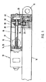
- Figure 1 is in schematic cross section, the one Side of a hydraulic piston-cylinder unit 10 with an eyelet 11 for mechanical connection shown, in addition to a combined drive and Control unit 12 is provided.
- This one has one reversible, designated overall with 13 Electric motor on, whose motor shaft 14 as Actuating shaft 15 ( Figures 2 and 4) a Actuator with one in the axial direction between 2 switch positions movable control rod 16 is formed.
- the actuating shaft 15 and the Control rod 16 are in a thread-like Wirktress, whose first embodiment in the Figures 2 and 3 and their alternative embodiment for this purpose is shown in Figure 4.
- a axial blind hole 17 in the control rod 16 with an internal thread 18 is provided, with an on this adapted external thread 19 of the actuating shaft 15th is provided.
- FIG. 2 and 3 An alternative embodiment is in the Figures 2 and 3 shown.
- Actuating shaft 15 with a radially projecting Actuating cam 20 provided along a helical groove 21 on the control rod 16 as in formed the groove 21 engaging bolt.
- the sliding movement is in axial Direction ends and takes the bolt 20 as Mitauer the control rod 16 with, causing the of the actuating shaft 15 output rotary motion then acting as a control shaft control rod is delivered.
- a Radial bearing 40 is provided at the to the actuating shaft 15th opposite free end of the control shaft 16 .
- the control shaft 16 and the actuating shaft 15 symmetrically surrounding Receiving cylinder 36 is with respect to the radial bearing 40th formed rotationally symmetrical.
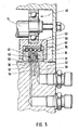
- FIG. 5 shows the embodiment according to the invention a valve device shown.
- the outer Bearing ring with clearance on the inside of the housing 35 is arranged or is based on this is an im Cross section U-shaped, downwardly open driver 50, in which a total of 61 designated, to one side, namely in Figure 6 downwardly open hollow body 61 is guided.
- a total of 51 designated valve sealing element provided which by the force of a compression spring 56 down, in Direction to a total of 57 designated Tax area expresses, in the form of a parallel to the Displacement direction of the control axis 16 extending Sealing surface is provided.
- a middle line 52 which from the pump comes and their pressure leads.
- On both sides in Displacement direction of which is offset to the a cylinder space leading line 53 and to the another cylinder space leading line 54 is provided.
- the valve sealing member 51 connects in each of the two switch positions, of which the left in Figure 5 is shown, the coming of the pump line 52 with one of the two lines to the two different cylinder spaces 53 and 54.
- a recess 58 surrounding a sealing edge 58 on, over which the connection of the two lines is effected in each case.
- In the recess is still one Bore 60 is provided, which the recess with the rearward portion of the valve sealing member 51 combines.
- a linear guide 62 (ball / roller bearing guide) on the back of the hollow cylinder 61 may be arranged which in turn on the back of a housing fixed Abutment 63 is supported, which is a plane Having bearing surface. This conditionally arises in the rear region of the hollow cylinder 61 no Sliding but only rolling friction, causing the Resistance when operating the valve device is further reduced.
Landscapes
- Engineering & Computer Science (AREA)
- Physics & Mathematics (AREA)
- Fluid Mechanics (AREA)
- Mechanical Engineering (AREA)
- General Engineering & Computer Science (AREA)
- Mechanically-Actuated Valves (AREA)
- Actuator (AREA)
- Fluid-Driven Valves (AREA)
- Fluid-Pressure Circuits (AREA)
Abstract
Description
Claims (16)
- Integrale Baueinheit, gebildet von einer die Betätigungsvorrichtung aufweisenden kombinierten Antriebs- und Steuereinheit (12), welche Betätigungsvorrichtung als mittels einer umschaltbaren Ventileinrichtung versehene Hydraulikpumpe (31) ausgebildet ist, von einer daneben angeordneten hydraulischen Kolben-Zylinder-Einheit (10) sowie gebildet von einem reversierbaren Elektromotor (13), wobei die Betätigungsvorrichtung eine in axialer Richtung zwischen zwei Schaltstellungen bewegbare Steuerstange (16) mit dem reversierbaren Elektromotor (13) zum Antrieb aufweist, wobei eine in beide Drehrichtungen drehbare Betätigungswelle (15) vorgesehen ist, wobei diese mit der Steuerstange (16) in einer über letztere bei Drehung in die eine Richtung in axialer Richtung auf die eine der beiden Schaltstellungen und bei Drehung in die andere Richtung auf die andere Schaltstellung hin bewegenden gewindeartigen Wirkverbindung steht, wobei die Steuerstange (16) zugleich als die von der Betätigungswelle (15) abgegebene Drehbewegung bei Erreichen der einen sowie der anderen axialen Schaltstellung in der einen bzw. anderen Drehrichtung weitergebende Steuerwelle (16) ausgebildet ist, wobei an der Steuerwelle (16) ein Exzenter (30) angeordnet ist, wobei dieser auf einen Pumpenkolben der Hydraulikpumpe (31) einwirkt und auf diesen eine hin- und hergehende Hubbewegung zum Zwecke des Pumpens der Hydraulikflüssigkeit über die den Pumpendruck führende Leitung (52) überträgt, wobei an dem der Betätigungswelle (15) entgegengesetzten freien Ende der Steuerwelle (16) eine axial verschiebliche Stütze (40) vorgesehen ist, wobei die Stütze (40) als Radiallager ausgebildet ist, dessen äusserer Lagerring mit Spiel an der Innenseite (35) des Gehäuses abgestützt ist, wobei am äußeren Lagerring des Radiallagers (40) ein von diesem in Axialrichtung der Steuerwelle (16) bewegbarer Mitnehmer (50) angeordnet ist, der in Umfangsrichtung des Radiallagers (40) gehäusefest gehalten ist, wobei der Mitnehmer (50) mit einem von diesem verschieblichen, die Ventileinrichtung betätigenden Ventildichtelement (51) versehen ist, wobei die von der Pumpe kommende Leitung (52) in der einen Schaltstellung der Ventileinrichtung nur an die eine zu dem einen Zylinderraum der hydraulischen Kolben-Zylinder-Einheit (10) führenden Leitung (53) und in der anderen Schaltstellung der Ventileinrichtung nur an die zu dem anderen Zylinderraum führenden andere Leitung (54) angeschlossen und wobei die jeweils nicht an die Pumpe angeschlossene Leitung mit dem Tank (55) verbunden ist.
- Baueiheit nach Anspruch 1, dadurch gekennzeichnet, dass die Wirkverbindung als axiale Sackbohrung (17) in der Steuerstange (16) mit einem Innengewinde (18) und als mit einem an dieses angepassten Aussengewinde (19) an der Betätigungswelle ausgebildet ist.
- Baueiheit nach Anspruch 1, dadurch gekennzeichnet, dass die Wirkverbindung als wendelartige Nut (21) an der Steuerstange (16) und als in diese Nut eingreifender Betätigungsnocken (20) an der Betätigungswelle (15) ausgebildet ist.
- Baueiheit nach Anspruch 3, dadurch gekennzeichnet, dass die Betätigungswelle (15) in eine Axial- bzw. Sackbohrung (17) der Steuerstange (16) eingreift und der Nocken (20) als quer zur Achsrichtung sich erstreckender und in die Nut (21) der Steuerstange (16) eingreifender Bolzen ausgebildet ist.
- Baueiheit nach Anspruch 1, dadurch gekennzeichnet, dass der Pumpenkolben in Richtung auf die Steuerwelle (16) hin mit der Kraft einer Feder (33) belastet ist.
- Baueiheit nach Anspruch 5, dadurch gekennzeichnet, dass auf dem Exzenter (30) der Steuerwelle (16) ein Kugellager (32) aufgesetzt ist und dass dessen äusserer Lagerring an der Rückseite des Pumpenkolbens anliegt.
- Baueiheit nach Anspruch 1, dadurch gekennzeichnet, dass das Gehäuse als die Steuerwelle (16) und die Betätigungswelle (15) vorzugsweise symmetrisch umgebender Aufnahmezylinder (36) ausgebildet ist.
- Baueiheit nach Anspruch 7, dadurch gekennzeichnet, dass der Aufnahmezylinder (36) bezüglich der Stütze (40) rotationssymmetrisch ausgebildet ist.
- Baueinheit nach Anspruch 1, dadurch gekennzeichnet, daß die eine Leitung als zu dem einen Zylinderraum (53) führenden Leitung und die andere Leitung (54) als zu dem anderen Zylinderraum führenden Leitung ausgebildet ist.
- Baueinheit nach Anspruch 1 oder 9, dadurch gekennzeichnet, daß das Ventildichtelement (51) mittels einer Druckfeder (56) gegen einen Steuerbereich (57) gedrückt ist.
- Baueinheit nach Anspruch 10, dadurch gekennzeichnet, daß das Ventildichtelement (51) im Bereich des Steuerbereichs (57) eine von einem umlaufenden Dichtrand (58) umgebene Ausnehmung (59) aufweist.
- Baueinheit nach Anspruch 11, dadurch gekennzeichnet, daß die Ausnehmung (59) über eine Bohrung (60) mit dem rückwärtigen, die Druckfeder (56) aufweisenden Teil des Ventildichtelements (51) verbunden ist, dessen -rückwärtige- hydraulisch wirksame Querschnittsfläche größer als die -vorderehydraulisch wirksame Querschnittsfläche der Ausnehmung (59) ist.
- Baueinheit nach einem der Ansprüche 1 oder 9 bis 21, dadurch gekennzeichnet, daß die von der Pumpe kommende Leitung (52), die zu dem einen Zylinderraum führende Leitung (53) und die zu dem anderen Zylinderraum führende Leitung (54) in dem Steuerbereich (57) münden, und die drei Mündungen -bezüglich der Steuerwelle (16)- in axialer Verschieberichtung mit der von der Pumpe kommenden Leitung (52) in der Mitte angeordnet sind.
- Baueinheit nach einem der Ansprüche 1 und 9 bis 13, dadurch gekennzeichnet, daß das Ventildichtelement (51) über einen es in Radialrichtung verschieblich aufnehmenden, einseitig offenen Hohlkörper (61) angeordnet ist, der entsprechend in dem Mitnehmer geführt ist.
- Baueinheit nach einem der Ansprüche 1 und 9 bis 14, dadurch gekennzeichnet, daß an der Rückseite des Hohlkörpers (61) eine Linearführung (62) angeordnet ist, die sich rückseitig an einem gehäusefesten Widerlager (63) abstützt.
- Baueinheit nach Anspruch 1, dadurch gekennzeichnet, daß das Ventildichtelement (51) aus Buntmetall besteht.
Applications Claiming Priority (7)
| Application Number | Priority Date | Filing Date | Title |
|---|---|---|---|
| DE19823949 | 1998-05-28 | ||
| DE19823949 | 1998-05-28 | ||
| DE19827441 | 1998-06-19 | ||
| DE19827441 | 1998-06-19 | ||
| DE19832306A DE19832306C2 (de) | 1998-06-19 | 1998-07-17 | Vorrichtung mit einer Steuerstange und mit einem von dieser betätigten Steuerhebel |
| DE19832306 | 1998-07-17 | ||
| EP99110209A EP0961192A3 (de) | 1998-05-28 | 1999-05-26 | Betätigungsvorrichtung |
Related Parent Applications (1)
| Application Number | Title | Priority Date | Filing Date |
|---|---|---|---|
| EP99110209A Division EP0961192A3 (de) | 1998-05-28 | 1999-05-26 | Betätigungsvorrichtung |
Publications (3)
| Publication Number | Publication Date |
|---|---|
| EP1505468A2 true EP1505468A2 (de) | 2005-02-09 |
| EP1505468A3 EP1505468A3 (de) | 2005-03-30 |
| EP1505468B1 EP1505468B1 (de) | 2006-07-19 |
Family
ID=33556482
Family Applications (1)
| Application Number | Title | Priority Date | Filing Date |
|---|---|---|---|
| EP04024698A Expired - Lifetime EP1505468B1 (de) | 1998-05-28 | 1999-05-26 | Baueinheit |
Country Status (1)
| Country | Link |
|---|---|
| EP (1) | EP1505468B1 (de) |
Family Cites Families (6)
| Publication number | Priority date | Publication date | Assignee | Title |
|---|---|---|---|---|
| DE687918C (de) * | 1936-07-22 | 1940-02-08 | Theodor Wedde | Getriebe zur Umwandlung einer hin und her gehenden Bewegung in eine Drehbewegung |
| FR1249404A (fr) * | 1959-11-14 | 1960-12-30 | Rech Etudes Production Sarl | Vérin hydraulique autonome à alimentation électrique et à commande électrique |
| JPS5129440Y1 (de) * | 1970-12-26 | 1976-07-24 | ||
| CH657433A5 (de) * | 1981-09-14 | 1986-08-29 | Sig Schweiz Industrieges | Vorrichtung zur begrenzung des drehwinkels bei schraubengetrieben und fluidische regeleinrichtung. |
| WO1987005368A1 (fr) * | 1986-03-06 | 1987-09-11 | Koeppen Detlef | Ensemble cylindre/pompe actionne par un milieu pressurise |
| JP2547230Y2 (ja) * | 1991-05-15 | 1997-09-10 | 日東工器株式会社 | 油圧作動機 |
-
1999
- 1999-05-26 EP EP04024698A patent/EP1505468B1/de not_active Expired - Lifetime
Also Published As
| Publication number | Publication date |
|---|---|
| EP1505468A3 (de) | 2005-03-30 |
| EP1505468B1 (de) | 2006-07-19 |
Similar Documents
| Publication | Publication Date | Title |
|---|---|---|
| DE4138313C2 (de) | Radialkolbenpumpe | |
| EP2025852B1 (de) | Motorisch angetriebener Linearaktuator | |
| EP0335083A1 (de) | Vorrichtung zur relativen Winkelverstellung zwischen zwei in Antriebsverbindung stehenden Wellen | |
| EP3638926A1 (de) | Parksperre für ein automatgetriebe in einem kraftfahrzeug | |
| DE3687876T2 (de) | Ausladungsventil fuer integrierte lenkeinrichtung. | |
| EP1537340A2 (de) | Scheibenbremse | |
| EP1205652B1 (de) | Variables Kompressionsverhältnis, zwei durch Öldruck betätigte Ventile in der Kurbelwelle | |
| DE2236257B2 (de) | Reibungsgetriebe mit veränderlicher Übersetzung | |
| DE3909910C2 (de) | ||
| EP2102524A2 (de) | Scheibenbremse mit elektromotorischen aktuator in selbstverstärkender bauart | |
| EP1437519A1 (de) | Geberzylinder für Kupplungsausrücksysteme | |
| EP0388440A1 (de) | Hydraulische hilfskraftlenkung. | |
| EP0326562B1 (de) | Drehschieberventil für hydraulische hilfskraftlenkungen | |
| WO2006117080A1 (de) | Verstellvorrichtung für eine brennkraftmaschine | |
| DE4429305C2 (de) | Nockenbetätigter Antiblockier-Bremssystem-Modulator | |
| DE10251550A1 (de) | Elektrohydraulischer Motor und hydraulisches Antriebsverfahren | |
| DE19620654B4 (de) | Verstellbare Axialkolbenmaschine in Schrägscheibenbauweise | |
| EP1505468A2 (de) | Baueinheit | |
| DE19832306C2 (de) | Vorrichtung mit einer Steuerstange und mit einem von dieser betätigten Steuerhebel | |
| DE4315895B4 (de) | Lenkkraftverstärker | |
| CH660055A5 (de) | Einrichtung zur aenderung der ventil- und/oder einspritzsteuerzeiten an einer hubkolbenbrennkraftmaschine. | |
| DE2336195C3 (de) | Servolenkung für Kraftfahrzeuge | |
| EP0961192A2 (de) | Betätigungsvorrichtung | |
| DE4202631A1 (de) | Axialkolbenmaschine, insbesondere hydropumpe der schiefscheibenbauart oder der schraegachsenbauart, deren durchsatzvolumen durch eine einstellvorrichtung einstellbar ist | |
| DE102006006684A1 (de) | Antriebseinheit für Hydraulik-Kolbenpumpen mit Exzenter eines Fahrzeugbremssystems |
Legal Events
| Date | Code | Title | Description |
|---|---|---|---|
| PUAI | Public reference made under article 153(3) epc to a published international application that has entered the european phase |
Free format text: ORIGINAL CODE: 0009012 |
|
| AC | Divisional application: reference to earlier application |
Ref document number: 0961192 Country of ref document: EP Kind code of ref document: P |
|
| AK | Designated contracting states |
Kind code of ref document: A2 Designated state(s): DE FR IT NL SE |
|
| AX | Request for extension of the european patent |
Extension state: AL LT LV MK |
|
| PUAL | Search report despatched |
Free format text: ORIGINAL CODE: 0009013 |
|
| AK | Designated contracting states |
Kind code of ref document: A3 Designated state(s): DE FR IT NL SE |
|
| AX | Request for extension of the european patent |
Extension state: AL LT LV MK |
|
| 17P | Request for examination filed |
Effective date: 20050601 |
|
| AKX | Designation fees paid |
Designated state(s): DE FR IT NL SE |
|
| GRAP | Despatch of communication of intention to grant a patent |
Free format text: ORIGINAL CODE: EPIDOSNIGR1 |
|
| GRAS | Grant fee paid |
Free format text: ORIGINAL CODE: EPIDOSNIGR3 |
|
| GRAA | (expected) grant |
Free format text: ORIGINAL CODE: 0009210 |
|
| AC | Divisional application: reference to earlier application |
Ref document number: 0961192 Country of ref document: EP Kind code of ref document: P |
|
| AK | Designated contracting states |
Kind code of ref document: B1 Designated state(s): DE FR IT NL SE |
|
| PG25 | Lapsed in a contracting state [announced via postgrant information from national office to epo] |
Ref country code: IT Free format text: LAPSE BECAUSE OF FAILURE TO SUBMIT A TRANSLATION OF THE DESCRIPTION OR TO PAY THE FEE WITHIN THE PRESCRIBED TIME-LIMIT;WARNING: LAPSES OF ITALIAN PATENTS WITH EFFECTIVE DATE BEFORE 2007 MAY HAVE OCCURRED AT ANY TIME BEFORE 2007. THE CORRECT EFFECTIVE DATE MAY BE DIFFERENT FROM THE ONE RECORDED. Effective date: 20060719 |
|
| REF | Corresponds to: |
Ref document number: 59913690 Country of ref document: DE Date of ref document: 20060831 Kind code of ref document: P |
|
| REG | Reference to a national code |
Ref country code: SE Ref legal event code: TRGR |
|
| ET | Fr: translation filed | ||
| PLBE | No opposition filed within time limit |
Free format text: ORIGINAL CODE: 0009261 |
|
| STAA | Information on the status of an ep patent application or granted ep patent |
Free format text: STATUS: NO OPPOSITION FILED WITHIN TIME LIMIT |
|
| 26N | No opposition filed |
Effective date: 20070420 |
|
| EUG | Se: european patent has lapsed | ||
| PG25 | Lapsed in a contracting state [announced via postgrant information from national office to epo] |
Ref country code: NL Free format text: LAPSE BECAUSE OF NON-PAYMENT OF DUE FEES Effective date: 20071201 |
|
| NLV4 | Nl: lapsed or anulled due to non-payment of the annual fee |
Effective date: 20071201 |
|
| REG | Reference to a national code |
Ref country code: FR Ref legal event code: ST Effective date: 20080131 |
|
| PG25 | Lapsed in a contracting state [announced via postgrant information from national office to epo] |
Ref country code: DE Free format text: LAPSE BECAUSE OF NON-PAYMENT OF DUE FEES Effective date: 20071201 |
|
| PG25 | Lapsed in a contracting state [announced via postgrant information from national office to epo] |
Ref country code: SE Free format text: LAPSE BECAUSE OF NON-PAYMENT OF DUE FEES Effective date: 20070527 |
|
| PG25 | Lapsed in a contracting state [announced via postgrant information from national office to epo] |
Ref country code: FR Free format text: LAPSE BECAUSE OF NON-PAYMENT OF DUE FEES Effective date: 20070531 |