EP1505546A2 - Procédé de représenter une image tridimensionelle par modélisation d'un deuxième objet relié à un premier objet - Google Patents
Procédé de représenter une image tridimensionelle par modélisation d'un deuxième objet relié à un premier objet Download PDFInfo
- Publication number
- EP1505546A2 EP1505546A2 EP04018585A EP04018585A EP1505546A2 EP 1505546 A2 EP1505546 A2 EP 1505546A2 EP 04018585 A EP04018585 A EP 04018585A EP 04018585 A EP04018585 A EP 04018585A EP 1505546 A2 EP1505546 A2 EP 1505546A2
- Authority
- EP
- European Patent Office
- Prior art keywords
- bone
- collision
- occurs
- multiple polygons
- angle
- Prior art date
- Legal status (The legal status is an assumption and is not a legal conclusion. Google has not performed a legal analysis and makes no representation as to the accuracy of the status listed.)
- Granted
Links
Images




Classifications
-
- G—PHYSICS
- G06—COMPUTING OR CALCULATING; COUNTING
- G06T—IMAGE DATA PROCESSING OR GENERATION, IN GENERAL
- G06T13/00—Animation
- G06T13/20—Three-dimensional [3D] animation
- G06T13/40—Three-dimensional [3D] animation of characters, e.g. humans, animals or virtual beings
-
- A63F13/10—
-
- A—HUMAN NECESSITIES
- A63—SPORTS; GAMES; AMUSEMENTS
- A63F—CARD, BOARD, OR ROULETTE GAMES; INDOOR GAMES USING SMALL MOVING PLAYING BODIES; VIDEO GAMES; GAMES NOT OTHERWISE PROVIDED FOR
- A63F13/00—Video games, i.e. games using an electronically generated display having two or more dimensions
- A63F13/45—Controlling the progress of the video game
-
- A—HUMAN NECESSITIES
- A63—SPORTS; GAMES; AMUSEMENTS
- A63F—CARD, BOARD, OR ROULETTE GAMES; INDOOR GAMES USING SMALL MOVING PLAYING BODIES; VIDEO GAMES; GAMES NOT OTHERWISE PROVIDED FOR
- A63F13/00—Video games, i.e. games using an electronically generated display having two or more dimensions
- A63F13/55—Controlling game characters or game objects based on the game progress
- A63F13/56—Computing the motion of game characters with respect to other game characters, game objects or elements of the game scene, e.g. for simulating the behaviour of a group of virtual soldiers or for path finding
-
- A—HUMAN NECESSITIES
- A63—SPORTS; GAMES; AMUSEMENTS
- A63F—CARD, BOARD, OR ROULETTE GAMES; INDOOR GAMES USING SMALL MOVING PLAYING BODIES; VIDEO GAMES; GAMES NOT OTHERWISE PROVIDED FOR
- A63F2300/00—Features of games using an electronically generated display having two or more dimensions, e.g. on a television screen, showing representations related to the game
- A63F2300/60—Methods for processing data by generating or executing the game program
- A63F2300/66—Methods for processing data by generating or executing the game program for rendering three dimensional images
- A63F2300/6607—Methods for processing data by generating or executing the game program for rendering three dimensional images for animating game characters, e.g. skeleton kinematics
-
- G—PHYSICS
- G06—COMPUTING OR CALCULATING; COUNTING
- G06T—IMAGE DATA PROCESSING OR GENERATION, IN GENERAL
- G06T2210/00—Indexing scheme for image generation or computer graphics
- G06T2210/21—Collision detection, intersection
Definitions
- the present invention relates to computer graphics, for example in video games. More particularly, the present invention relates to a technique for drawing a three-dimensional image by modeling a first object and a second object that independently operate at portions other than their connection point.
- a three-dimensional game which causes an object such as a character and the like to operate in a virtual three-dimensional space and displays an image obtained by perspective-transforming the object by a virtual camera, is common in recent video games.
- the object existing in the virtual three-dimensional space must respond to various external forces (for example, wind force). It is an important task in the three-dimensional game to reproduce such an external influence in the operation of the object to create a realistic image.
- Unexamined Japanese Patent Publication No. 2003-51030 discloses a method for generating a three-dimensional image that can realistically reproduce a state that clothes, which a character wears, are waving in the wind.
- a connection degree where a vertex of each polygon is connected to each bone and a reference amount of movement, which is a maximum value of an amount of movement of a vertex connected for each bone are preset.
- an amount of movement of each vertex of each polygon and a direction of movement thereof are obtained based on the set connection degree and reference amount of movement to calculate a position of each polygon.
- the vertex position of the polygon is calculated under the influence of only an external force such as wind by this method, a position, which cannot be present in reality, is calculated as the vertex position of the polygon in some cases.
- the position, which cannot be present in reality is a position where a polygon that forms the clothes falls in the body of the character.
- the operation of the character itself is generally calculated using kinematics and dynamics.
- the inverse kinematics and the inverse dynamics are also applied to prevent the character from breaking through a wall and the joint of the character from being bent more than a set amount.
- the calculation becomes extremely complicated and the number of calculations increases as compared with the kinematics and the dynamics.
- active operations such as walking and running can be calculated by the inverse kinematics and the inverse dynamics, there is a problem that a passive operation such as waving of clothes by the influence of the external force such as wind cannot be appropriately calculated by the inverse kinematics and the inverse dynamics.
- An object of the present invention is to draw a three-dimensional image with a small amount of calculation as modeling operations of a first object and a second object, which independently operates at portions other than their connection point.
- a three-dimensional image drawing apparatus draws a three-dimensional image by modeling a first object and a second object that is connected to the first object and includes a bone defining display positions of multiple polygons.
- the second object is capable of operating, at a portion other than a connection point, independently of the first object.
- the three-dimensional image drawing apparatus includes a bone position calculator that calculates a position of a bone included in the second object when the second object moves according to a predetermined operation condition.
- the three-dimensional image drawing apparatus further includes a collision detector that determines whether the second object is where no collision with the first object occurs, based upon the calculated position of the bone.
- the three-dimensional image drawing apparatus further includes a bone position corrector that recalculates the position of the bone included in the second object to be where no collision with the first object occurs when the second object is determined as being where collision with the first object occurs.
- the three-dimensional image drawing apparatus further includes a polygon position calculator that calculates the position of each of the polygons that form the second object with reference to the position of the bone, which is located where no collision with the first object occurs.
- the three-dimensional image drawing apparatus further includes an image rendering system that draws the polygons that form the second object according to the position calculated by the polygon position calculator to create an image where the first and second objects are modeled.
- the position of the bone is corrected to where no collision with the first object occurs by the bone position corrector.
- the position of each polygon that forms the second object is calculated with reference to the position of the bone, which is located where no collision occurs.
- the position where no collision occurs is calculated to draw each polygon, so that a natural and realistic image is drawn. This eliminates the need for determining collision for each polygon to make it possible to draw the image with a small number of calculations.
- a three-dimensional image drawing apparatus draws a three-dimensional image by modeling a first object, which is formed by multiple polygons, and a second object, which is formed by multiple polygons and includes a bone defining the display positions of the multiple polygons.
- the second object is capable of moving, at a portion, other than a connection point independently of the first object.
- the three-dimensional image drawing apparatus has a program memory that stores a program and a processor that executes the program.
- the program causes the processor to calculate the position of each bone included in the second object when the second object moves according to a predetermined operation condition.
- the program further causes the processor to determine whether the second object is where no collision with the first object occurs at the calculated position of the bone.
- the program further causes the processor to recalculate the position of the bone included in the second object to be where no collision with the first object occurs when the second object is determined as being where collision with the first object occurs.
- the program further causes the processor to calculate the position of each of the polygons that form the second object with reference to the position of the bone, which is located where no collision with the first object occurs.
- the program further causes the processor to draw the polygons that form the second object according to the calculated position to create an image where the first and second objects are modeled.
- the program stored in the memory in the three-dimensional image drawing apparatus according to the second aspect of the present invention can be recorded on a computer-readable storage medium.
- the computer-readable storage medium may be a storage medium constructed to be removably loaded in the computer apparatus and provided separately from the computer apparatus.
- the computer-readable storage medium may be a storage medium such as a fixed disc device that is included in the computer apparatus and provided together with the computer apparatus.
- the data signal can be superimposed on a carrier wave from a server apparatus existing on a network and the result is distributed via the network.
- the three-dimensional image drawing apparatuses it is possible to use a general-purpose computer such a personal computer, etc., in addition to a dedicated video game apparatus.
- a general-purpose computer such as a personal computer, etc.
- electronic equipment capable of operating as a computer apparatus such as a cellular phone, etc.
- the apparatuses may be portable or stationary.
- a three-dimensional image drawing method draws a three-dimensional image by modeling a first object and a second object that is connected to the first object and includes a bone defining display positions of multiple polygons.
- the second object is capable of moving, at a portion other than a connection point, independently of the first object.
- the three-dimensional image drawing method calculates a position of a bone included in the second object when the second object moves according to a predetermined operation condition.
- the three-dimensional image drawing method further determines whether the second object is where no collision with the first object occurs at the calculated position of the bone.
- the three-dimensional image drawing method further recalculates the position of the bone included in the second object to be where no collision with the first object occurs when the second object is determined as being where collision with the first object occurs.
- the three-dimensional image drawing method further calculates the position of each of the multiple polygons that form the second object with reference to the position of the bone, which is located where no collision with the first object occurs.
- the three-dimensional image drawing method further draws the polygons that form the second object according to the calculated position to create an image where the first and second objects are modeled.
- This embodiment shows an example of a case in which the present invention is applied to draw an image of a player character in a three-dimensional video game.
- FIG. 1 is a view illustrating a configuration of a video game apparatus 100 that executes a three-dimensional video game according to this embodiment.
- the video game apparatus 100 is mainly constructed to include a video game main body 101.
- the video game main body 101 includes a control section 103, a RAM (Random Access Memory) 105, a hard disk drive (HDD) 107, a sound processor 109, a graphics processor 111, a DVD/CD-ROM drive 113, a communications interface 115, and an interface section 117, which are connected to an internal bus 119.
- the sound processor 109 of the video game main body 101 is connected to a sound output device 125, which is a speaker, and the graphics processor 111 is connected to a display device 121 having a display screen 122.
- a storage medium (DVD-ROM or CD-ROM) 131 can be attached to the DVD/CD-ROM drive 113.
- the communications interface 115 is connected to a network 151.
- An input section (controller) 161 and a memory card 162 are connected to the interface section 117.
- the control section 103 includes a CPU (Central Processing Unit), a ROM (Read Only Memory), etc., and executes a program stored on the HDD 107 or the storage medium 131 to control the video game apparatus 100.
- the control section 103 has an internal timer.
- the RAM 105 is a work area for the control section 103.
- the HDD 107 is a storage area for storing a program and data. In the case where a program executed by the control section 103 instructs the sound processor 109 to output a sound, the sound processor 109 interprets the instruction and outputs a sound signal to the sound output device 125.
- the graphics processor 111 develops an image onto frame memory 112 and outputs a video signal, which displays the image on the display screen 122 of the display device 121 according to a drawing command output from the control section 103. It is assumed that one frame time of the image included in the outputting video signal is, for example, 1/30 sec.
- the frame memory 112 has areas where images for two frames are developed, and the images are developed alternately in the respective areas for each frame.
- the DVD/CD-ROM drive 113 reads the program and data from the storage medium 131.
- the communications interface 115 is connected to the network 151 to perform communications with other computers.
- the interface section 117 outputs input data sent from the input section 161 to the RAM 105, and the control section 103 interprets it to carry out arithmetic processing.
- the input section 161 includes a directional key and multiple operation keys.
- the directional key is used to move a character (to be described later) and a cursor.
- the operation button is used to input a predetermined instruction.
- the interface section 117 forwards data, indicative of the progress of the game stored in the RAM 105, to the memory card 162 based on the instruction from the control section 103.
- the interface section 117 reads data of the game from the memory card 162 and transfers the read data to the RAM 105 based on the instruction from the control section.
- the program and data for performing the game by the video game apparatus 100 are first stored on, for example, the storage medium 131.
- the program and data are read by the DVD/CD-ROM drive 113 and loaded onto the RAM 105 at the time of execution.
- the control section 103 processes the program and data loaded onto the RAM 105, outputs a drawing command to the graphics processor 111, and outputs an instruction of a sound output to the sound processor 109.
- Intermediate data is stored in the RAM 105 while the control section 103 performs processing.
- a player operates the input section 161 to move a player character on a field formed in a virtual three-dimensional space, thereby the game is progressed.
- the virtual three-dimensional space where the field is formed is positioned by a world coordinate system.
- the field is structured by multiple surfaces, and coordinates of vertexes of the respective structural surfaces are fixed as characteristic points.
- a state when wind blows is simulated in the three-dimensional space in which the player character moves. For example, a wind direction and a wind speed for each frame are decided according to a random number obtained for each frame and data of wind direction and wind speed relating to previous several frames.
- FIG 2 is a view illustrating a configuration of the player character used in this three-dimensional video game.
- a player character 200 includes a head 202, a body 203, an arm 204, and a leg 205. Hair 201 in a ponytail style is added to the head 202.
- Each portion of the player character 200 includes multiple polygons, and the characteristic point (vertex of each polygon) is fixed by the coordinates in a local coordinate system.
- the portions of the the hair 201 excluding an end portion connected to the head 202 can be moved independently of the movement of the head 202.
- virtual bones 301 to 305 and 311 to 317 are provided in the player character 200.
- the position of each polygon that forms the player character 200 is decided by the positions of these bones 301 to 305 and 311 to 317.
- the positions of bones 311 to 317 provided to the portions other than the hair 201 are decided by only a passive operation of the player character 200.
- the positions of bones 311 to 317 are decided by a conventional method, such as kinematics and dynamics.
- the bones 301 to 305 provided to the hair 201 are connected to one another through joints 321 to 324 sequentially, and operate passively upon receiving an external force instead of the active operation of the player character 200.
- the external force to be added to the hair 201 includes at least gravity reflected by the weight of the hair 201, a kinetic inertial force generated by the operation of the player character 200, and a force caused by wind flowing in the virtual three-dimensional space. Moreover, there is a case that the amount of force differs for each portion.
- the weight of the hair 201 is preset based on each of the bones 301 to 305 as a unit in order to calculate the positions of the bones 301 to 305. It is assumed that the weight of the hair 201 is low enough to neglect the influence exerted on the passive operation of the player character 200.
- FIGS. 3A and 3B are views each explaining movement of the hair 201.
- FIG. 3A when the player character 200 receives the wind from the front, the hair 201 waves in a backward direction of the head 202 and body 203.
- FIG. 3B when the player character 200 receives the wind from the back, the hair 201 waves in the direction of the head 202 and body 203.
- the hair 201 is operated passively according to the kinetic inertia.
- a virtual reference axis 300 is set to the player character 200 every time bone positioning is performed.
- the reference axis 300 is set on a straight line connecting, for example, the position of a connected portion between the hair 201 and the head 202 to a predetermined position, which is a back side of the body 203.
- the reference axis 300 is also moved.
- the positions of the bones 301 to 305 provided to the hair 201 that are moved passively as described above can be also calculated using the conventionally used method based on an external force which is passively received according to the kinetic inertia and wind.
- the polygon which forms the hair 201 positioned according to the bones 301 to 305, may fall in the interior of the head 202 and the interior of the body 203 (this case is hereinafter called a collision) depending on the magnitude of the external force acting on the hair 201.
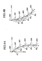
- an angle formed by the reference axis 300 and the bone 301, an angle formed by the bone 301 and the bone 302, an angle formed by the bone 302 and the bone 303, an angle formed by the bone 303 and the 304, and an angle formed by the bone 304 and the bone 305 are respectively fixed within predetermined reference angles.
- the matrix operation that moves an X axis of the world coordinate system to the reference axis is performed to determine the reference angle and the X axis can be returned to the original world coordinate system by an inverse matrix operation.
- FIGS. 4A and 4B are views each explaining the fixed reference angles of the bones 301 to 305. Since the coordinate system where the direction of the reference axis 300 is used as an x-axial direction, there is no need to determine an x component here. As illustrated in FIG.
- reference angles which are shown by dotted lines, are fixed to a Y component ⁇ 1y of an angle formed by the reference axis 300 and the bone 301, a Y component ⁇ 2y of an angle formed by the bone 301 and the bone 302, a Y component ⁇ 3y of an angle formed by the bone 302 and the bone 303, a Y component ⁇ 4y of an angle formed by the bone 303 and the bone 304, and a Y component ⁇ 5y of an angle formed by the bone 304 and the bone 305, respectively.
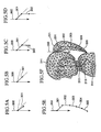
- FIGS. 5A to 5F are views each explaining the method for positioning the bones 301 to 305 and 311 to 317 and the positioning of each polygon. Though no explanation is given for separate y components and z components of the respective angles, these components are typically separately calculated.
- the positions of the bones 311 to 317 provided to the portions other than the hair 201 are decided by the conventionally used method.
- the positions of the bones 311 to 317 are decided, the positions of the polygons, which form the head 202, the body 203, the ann 204, and the leg 305, respectively, are naturally decided.
- the connected portion between the hair 201 and the head 202 and a predetermined position of the back of the body 203 are obtained, so that the reference axis 300 is set.
- the position of the bone 301 which is the closest to the head 202, is calculated according to the external force that the hair 201 receives regardless of the presence of the head 202 and body 203 of the player character 200. Then, an angle ⁇ 1 formed by the bone 301 and the reference axis 300 at the calculated position is obtained. As illustrated in FIG 5A, when the calculated angle ⁇ 1 exceeds the range of the reference angle shown by the dotted lines, the position of the bone 301 is corrected to the position at which the angle ⁇ 1 is set to the reference angle as illustrated in FIG. 5B. The corrected position is set as a position of the bone 301.
- the position of the bone 302 is calculated according to the external force that the hair 201 including the bone 302 and a portion, which is closer to the tip portion than the bone 302, receives regardless of the presence of the head 202 and body 203. Then, an angle ⁇ 2 formed by the bone 302 and the bone 301 is obtained at the calculated position. As illustrated in FIG. 5C, when the calculated angle ⁇ 2 exceeds the range of the reference angle shown by the dotted lines, the position of the bone 302 is corrected to the position at which the angle ⁇ 2 is set to the reference angle. The corrected position is set as a position of the bone 302.
- the positions of the bones 303 to 305 are sequentially set. Accordingly, the positions of all bones 301 to 305 and 311 to 317 of the player character 200 are set. As illustrated in FIG. 5F, the position of each polygon that forms each portion of the player character 200 is decided using only the positions of the bones 301 to 305 and 311 to 317 as a reference.
- the coordinates of the local coordinate system which show the positions of the bones 301 to 305 and 311 to 317 of the player character 200, are transformed to the coordinates of the world coordinate system.
- the position of vertexes of the respective polygons, which form the player character 200, can be specified according to the position of the bones 301 to 305 and 311 to 317 in the local coordinate system.
- the coordinates of the local coordinate system, which show the positions of the vertexes of the respective polygons are also transformed to the coordinates of the world coordinate system.
- an image of the state that the player character 200 moves on the field in the virtual three-dimensional space is projected on the display screen 122 and recognized by the player.
- a viewing coordinate system is used, and the coordinates of the world coordinate system are transformed to the coordinates of the viewing coordinates.
- a Z buffer method is used as the hidden surface removal method.
- the control section 103 After transforming the coordinates of the world coordinate system to the coordinates of the viewing coordinate system, the control section 103 sends the coordinates of each characteristic point to the graphics processor 111 and outputs a drawing instruction thereto.
- the graphics processor 111 updates the contents of a Z buffer to leave data of a point existing in the front side in connection with each characteristic point based on the drawing instruction. Then, the graphics process 111 develops image data of the relevant characteristic point onto the frame memory 112 every time data of the Z buffer is updated.
- FIG. 6 is a view illustrating a main processing in the three-dimensional video game according to an embodiment.
- the main processing generates an image corresponding to one frame and is performed by timer interruption every 1/30 second.
- the main processing may be performed by timer interruption every single field period (1/60 second) or every two frames (1/15 second) depending on the amount of processing.
- the control section 103 obtains random numbers for deciding the wind direction and wind speed by executing a random function, and calculates the wind direction and wind speed of the relevant frame according to the obtained random numbers and data of the wind direction and the wind speed relating to several previous frames (step S101).
- the calculated data of the wind direction and wind speed are stored in a predetermined area of the RAM 105 for the latest several frames.
- the control section 103 determines whether an instruction for operating the player character 200 by the player is input from the input section 161 (step S102). When the instruction for operating the player character 200 is not input, the control section 103 determines whether the player character 200 is in a stationary state in the previous frame (step S104). When the player character 200 is in the stationary state, the processing flow proceeds to step S106 directly.
- the control section 103 moves the positions (world coordinate system) of the bones 311 to 317 provided to the portions other than the hair 201 of the player character 200 according to the instruction content of the operation from the current state (namely, state according to the bones 311 to 317 decided in the previous frame). In this case, the control section 103 considers the positions of the bones 311 to 317 in the previous several frames in order to express a state that movement of the player character 200 is accelerated (sep S103). Then, the processing flow proceeds to step S106.
- step S104 When the player character 200 is not in the stationary state in step S104, the control section 103 moves the positions (world coordinate system) of the bones 311 to 317 provided to the portions other than the hair 201 of the player character 200 to return the current state to a predetermined stationary state. In this case, the control section 103 considers the positions of the bones 311 to 317 in the previous several frames to prevent the player from feeling that something is different by stopping the player character 200 rapidly (step S105). Then, the processing flow proceeds to step S106.
- step S106 the control section 103 sets the reference axis 300 for detecting the positions of the bones 301 to 305 provided to the hair 201 based on the positions of the bones 311 and 317 of the player character 200 moved in step S103 or S105 or those that are not moved from the previous frame.
- the control section 103 performs hair bone position decision processing for detecting the positions of the bones 301 to 305 provided to the hair 201 (step S107).
- FIG. 7 is a flowchart specifically illustrating the hair bone position decision processing.
- the force applied to the hair 201 of the player character 200 includes only gravity, i.e., the weight of the hair 201, a kinetic inertial force according to the operation of the player character 200 and force received by the wind flowing in the virtual three-dimensional space.
- the control section 103 performs loop processing by changing a value of N to 1, 2, 3, 4, and 5 sequentially (step S201 to S201').
- the control section 103 calculates gravity received by portions including bone 30N and thereunder in the hair 201 of the player character 200 (step S202).
- the control section 103 calculates a kinetic inertial force received by the portions including bone 30N and thereunder in the hair 201 based on the position in the current frame and the position in the previous frame in connection with the bone of the head 202 to which the hair 201 is connected (step S203).
- the control section 103 calculates force, which the portions including bone 30N and thereunder in the hair 201 receive by the wind flowing in the virtual three-dimensional space, according to the wind speed and wind direction calculated in step S101 (step S204).
- the control section 103 calculates a position of the bone 30N (world coordinate system) based on all forces received by the portions including bone 30N and thereunder in the hair 201 calculated in steps S202 to S204. At the time of calculating the position of the bone 30N, reference is made to the position of the bone 30N in the previous frame (step S205).
- the control section 103 calculates a y component and a z component in a coordinate system where the direction of the reference axis 300 is an x-axial direction in connection with an angle that the bone 30N forms with an upper portion (which is reference axis 300 when the bone 30N is 301 and which is each of bones 301 to 304 when the bone 30N is each of bones 302 to 305) (step S206).
- the control section 103 determines whether both y component and z component of the angle that the bone 30N forms with the upper portion are within the range of the reference angle (step S207). When both the y component and z component are within the range of the reference angle and the value of N is not changed up to 5, the control section 103 updates the value of N to perform processing in the loop again. When both the y component and z component are within the range of the reference angle and the value of N is incremented to 5, the processing in this flowchart ends and processing returns to the processing in FIG. 6.
- the control section 103 corrects a position (world coordinate system) of the bone 30N to the position where both the y component and z component of the angle that the bone 30N forms with the upper portion are at the reference angle (step S208).
- the control section 103 updates the value of N to perform processing in the loop.
- the processing in this flowchart ends and processing returns to the processing in FIG 6.
- the control section 103 calculates the position (world coordinate system) of the vertex of each polygon that forms each of the portions 201 to 205 of the player character 200 with reference to the positions of the bones 301 to 305 and 311 to 317 of the player character 200 decided in the steps up to S107. More specifically, when the positions of the bones 301 to 305 and 311 to 317 in the local coordinate system are specified, the positions of the vertexes of the respective polygons in the local coordinate system are naturally specified.
- the control section 103 may transform the coordinates of each polygon in the local coordinate system to the coordinates of the world coordinate system (step S108). There is no need to calculate the positions (world coordinate system) of the vertexes of the polygons that form the portions other than the player character 200 in the virtual three-dimensional space since these positions are fixed.
- the control section 103 determines a viewpoint position, a direction of a visual axis, and a magnitude of a visual angle as required, and sets a virtual camera for performing perspective-transformation.
- the conventional method may be applied to processing for setting the virtual camera (step S109).
- the control section 103 perspective-transforms the virtual three-dimensional space including the player character onto the virtual screen by the virtual camera, and performs display processing for generating a two-dimensional image to be displayed on the display screen 122 (step S110).
- the control section 103 ends the main processing. The main processing is executed again with start timing of a next frame period.
- step S110 Among the coordinates of the vertexes of the respective polygons that form the virtual three-dimensional space including the player character 200, the control section 103 transforms the coordinates of the vertex of each polygon included in a range, which is at least perspective-transformed onto the virtual screen, from the coordinates of the world coordinate system to the coordinates of the viewing coordinate system.
- the control section 103 sends the coordinates of the vertex of each polygon transformed to the viewing coordinate system to the graphics processor 111, and outputs a drawing command to the graphics processor 111.
- the graphics processor 111 In connection with the respective pixels that form the respective surfaces, the graphics processor 111, which has received the drawing command, updates the contents of the Z buffer to leave data of a polygon existing in the front side based on the coordinates of the viewing coordinate system. When the contents of the Z buffer are updated, the graphics processor 111 develops image data of the relevant pixel onto the frame memory 112. The graphics processor 111 also executes processing such as shading, texture mapping and the like to image data to be developed.
- the graphics processor 111 reads image data developed onto the frame memory 112, sequentially, and adds a synchronization signal thereto to generate a video signal, and outputs the video signal to the display device 121.
- the display device 121 displays an image corresponding to the video signal output from the graphics processor 111 on the display screen 122.
- the image on the display screen 122 is switched every single frame period, so that the player can view the image including the player character 200 moving on the field and the hair 201 moving in response to the external force.
- the hair 201 of the player character 200 moves under the influence of the external force separately from the operation of the player character 200.
- a magnitude of the received external force differs from portion to portion.
- Five bones 301 to 305 are provided to the hair 201 and a receiving force for each portion corresponding to each bone is calculated. Accordingly, the amount that the hair 201 is moved in response to the external force for each portion can be reproduced realistically.
- any angle may be logically possible.
- a reference angle at which the hair 201 does not collide with the other portion of the player character is predetermined. The positions of the bones 301 to 305 are corrected to be at the reference angle when the angle that each bone forms with the upper portion is not in the range of the reference angle by the calculation based on the external force.
- the positions of the bones 301 to 305 provided to the hair 201 are guaranteed to be located where collisions cannot occur.
- such a phenomenon that the polygon forming the hair 201 falls in the other portion of the player character 200 does not occur in the image displayed on the display screen 122.
- a collision between the hair 201 and the other portion of the player character 200 is determined at the time of drawing the image according to the angle, which each of the bones 301 to 305 forms with the upper portion. This may eliminate the need for using an object for collision detection that is not originally present in the virtual three-dimensional space. The lack of need for the collision detection object-can be applied to not only the bone 301 connected to the head 202 but also the bones 302 to 305.
- collision detection for preventing collision of the hair 201 is only performed for the bones 301 to 305. If the positions of the bones 301 to 305 provided to the hair 201 are decided, the positions of the vertexes of the respective polygons that form the hair 201 can be decided based on the decided positions of the bones 301 to 305. In other words, since collision detection does not have to be performed for each vertex of the polygon, the amount of calculations required for collision detection can be reduced.
- An image which is perspective-transformed and displayed on the display screen 122, can be a realistic image that expresses a curvature smoothly.
- the aforementioned embodiment explained the case in which the present invention was applied for modeling the operation of the hair 201 of the player character 200.
- the object in which the image is drawn by applying the present invention is not limited to the aforementioned embodiment. If an object is one that is connected to another object and operated independently of the relevant other object at the portion other than the connection point, an image can be drawn for the other kind of object by applying the present invention. Regarding the number of bones included in the object, any number, which is one or more, can be applied. The object may be one that is connected to the other object at two portions.
- the present invention can be applied to a case in which an operation of a wide object is modeled as well as a narrow object such as hair 201.
- FIG 8 is a view illustrating a configuration of a character having a wide object.
- a character 400 wears a cloak as a wide object. Since it is difficult to express an operation of the cloak 500 by only a series of bones, a set of bones 501 including bones 511 to 514, a set of bones 502 including bones 521 to 524, a set of bones 503 including bones 531 to 534, and a set of bones 504 including bones 541 to 544 are provided to the cloak 500.
- Individual reference axes may be provided to the sets of bones 501 to 504, respectively.
- a common reference axis may be provided to the sets of bones 501 to 504.
- the multiple sets of bones 501 to 504 are provided in this way to make it possible to apply the present invention even when an image of the wide object such as the cloak 500 is drawn.
- the reference axis 300 was provided separately from the bones 311 to 317 provided to the portions other than the hair 201 of the player character 200.
- the reference axis may be provided to any one of the bones (particularly, the bone 311 of the head 202 to which the hair 201 is connected). In the case where the tip portion of the hair 201 reaches only a certain range of the head 202 without reaching the back of the player character 200, this is especially useful since the reference axis can be easily provided.
- the hair 201 of the player character 200 moves under the inertial force of the motion due to the operation of the player character 200, the force of the wind flowing into the virtual three-dimensional space, and the gravity due to its own weight.
- the hair 201 of the player character 200 may move in response to another kind of external force.
- another character may be operated to bit the player character 200 on the hair 201 with its hand or a weapon. In this case, determination of the collision with another character's hand or weapon-can be executed with reference to the positions of the bones 301 to 305.
- the aforementioned embodiment explained the case in which the present invention was applied at the time of drawing the image of the object, which was passively operated by the external force.
- the present invention can be applied at the time of drawing the image of the object, which operates actively as in the character's hand and leg, and the image of the object, which operates actively and is operated passively by the external force.
- the hair 201 collided with the other portion of the player character 200 it was determined whether the hair 201 collided with the other portion of the player character 200 depending on whether the angle, which each of the bones 301 to 305 provided to the hair 201 formed with the upper portion, was in the range of the reference angle.
- the collision detection can be actually performed for only the bones 301 to 305 provided to the hair 201 using the object for collision detection.
- the position of each polygon may be decided according to only the positions of the given bones 301 to 305.
- the video game apparatus 100 which was a special-purpose machine, was used as a platform.
- any apparatus such as a general-purpose computer may be used if the apparatus includes the same structural components as those of the video game main body 101 and a function of drawing a three-dimensional image.
- a portable video game apparatus which contains the display device 121 and the sound output device 125 in the same cabinet as that of the video game main body 101, may also be used.
- a semiconductor memory card may be used as the storage medium 131 in place of a DVD-ROM or CD-ROM.
- a card slot for inserting the memory card may be formed in place of the DVD/CD-ROM drive 113.
- the program and data relating to the present invention may be prestored to the HDD 107 instead of being stored to the storage medium 131.
- any storage medium may be used according to the physical form of hardware and the distribution thereof.
- the program for executing the video game of the present invention may be stored on a fixed disc apparatus provided in a Web server apparatus existing on the network 151.
- the Web server apparatus may convert the program and data stored in the fixed disc apparatus to a signal and superimpose the signal on a carrier wave, and distribute it to the video game main body 101 via the network 151 and the communications medium 141.
- the program, which the communications interface 115 received from the Web server apparatus, can be stored in the HDD 107 and loaded to the RAM 105 at an executing time.
- the aforementioned embodiment explained the case in which the present invention was applied to draw the image of the game in the three-dimensional video game.
- the present invention can be used in the field of the computer graphics processing for drawing a three-dimensional image without being limited to the three-dimensional video game.
- the present invention is particularly suitable for use in the field of the three-dimensional computer graphics processing for drawing a three-dimensional image with real time. Even if this is not one that is applied as a part of the program of the video game, a program including a function of drawing the three-dimensional image as mentioned above can be distributed by the same method as that of the program for the video game.
Landscapes
- Engineering & Computer Science (AREA)
- Multimedia (AREA)
- Theoretical Computer Science (AREA)
- Physics & Mathematics (AREA)
- General Physics & Mathematics (AREA)
- Human Computer Interaction (AREA)
- Processing Or Creating Images (AREA)
Applications Claiming Priority (2)
| Application Number | Priority Date | Filing Date | Title |
|---|---|---|---|
| JP2003287885A JP3926307B2 (ja) | 2003-08-06 | 2003-08-06 | 3次元画像描画装置及び方法、プログラム、並びに記録媒体 |
| JP2003287885 | 2003-08-06 |
Publications (3)
| Publication Number | Publication Date |
|---|---|
| EP1505546A2 true EP1505546A2 (fr) | 2005-02-09 |
| EP1505546A3 EP1505546A3 (fr) | 2006-05-03 |
| EP1505546B1 EP1505546B1 (fr) | 2010-04-21 |
Family
ID=33550032
Family Applications (1)
| Application Number | Title | Priority Date | Filing Date |
|---|---|---|---|
| EP04018585A Expired - Lifetime EP1505546B1 (fr) | 2003-08-06 | 2004-08-05 | Procédé de représenter une image tridimensionelle par modélisation d'un deuxième objet relié à un premier objet |
Country Status (4)
| Country | Link |
|---|---|
| US (1) | US20050075557A1 (fr) |
| EP (1) | EP1505546B1 (fr) |
| JP (1) | JP3926307B2 (fr) |
| DE (1) | DE602004026666D1 (fr) |
Cited By (4)
| Publication number | Priority date | Publication date | Assignee | Title |
|---|---|---|---|---|
| CN101079154B (zh) * | 2007-03-02 | 2010-05-26 | 腾讯科技(深圳)有限公司 | 一种角色动画实现方法及系统 |
| WO2013189101A1 (fr) * | 2012-06-20 | 2013-12-27 | 浙江大学 | Procédé de modification de portrait et de modélisation de cheveux sur la base d'une image unique |
| EP2692399A1 (fr) * | 2012-08-01 | 2014-02-05 | Square Enix Co., Ltd. | Dispositif d'affichage d'objet |
| CN111127606A (zh) * | 2019-12-25 | 2020-05-08 | 北京像素软件科技股份有限公司 | 柔体飘动方向控制方法、装置及电子设备 |
Families Citing this family (17)
| Publication number | Priority date | Publication date | Assignee | Title |
|---|---|---|---|---|
| JP4160091B2 (ja) * | 2006-12-08 | 2008-10-01 | 株式会社スクウェア・エニックス | ゲーム装置及びゲーム要素の生成方法、並びにプログラム及び記録媒体 |
| JP4567027B2 (ja) * | 2007-06-06 | 2010-10-20 | 株式会社コナミデジタルエンタテインメント | 画像処理装置、画像処理方法及びプログラム |
| US8941642B2 (en) * | 2008-10-17 | 2015-01-27 | Kabushiki Kaisha Square Enix | System for the creation and editing of three dimensional models |
| JP2010134798A (ja) * | 2008-12-05 | 2010-06-17 | Namco Bandai Games Inc | プログラム、情報記憶媒体、ゲーム装置、及びゲームシステム |
| JP4733757B2 (ja) * | 2009-06-05 | 2011-07-27 | 株式会社スクウェア・エニックス | ポリゴン処理装置,プログラム及び情報記録媒体 |
| JP5155262B2 (ja) * | 2009-08-07 | 2013-03-06 | 株式会社コナミデジタルエンタテインメント | 画像生成装置、画像生成方法、ならびに、プログラム |
| US9098944B2 (en) * | 2010-03-04 | 2015-08-04 | Pixar | Scale separation in hair dynamics |
| JP5190524B2 (ja) | 2011-02-16 | 2013-04-24 | 株式会社スクウェア・エニックス | オブジェクト動作装置及び方法、並びにプログラム |
| JP5118220B2 (ja) | 2011-02-16 | 2013-01-16 | 株式会社スクウェア・エニックス | 動作モデリング装置及び方法、並びにプログラム |
| US9785729B2 (en) * | 2012-12-14 | 2017-10-10 | Nvidia Corporation | Technique for simulating the dynamics of hair |
| JP6329616B1 (ja) * | 2016-11-28 | 2018-05-23 | 株式会社スクウェア・エニックス | プログラム、コンピュータ装置、及び、判定方法 |
| EP3797404A4 (fr) * | 2018-05-22 | 2022-02-16 | Magic Leap, Inc. | Systèmes squelettiques permettant d'animer des avatars virtuels |
| JP2020113094A (ja) * | 2019-01-15 | 2020-07-27 | 株式会社シーエスレポーターズ | 拡張現実空間に配置される3dオブジェクトを生成する方法 |
| US11423515B2 (en) | 2019-11-06 | 2022-08-23 | Canon Kabushiki Kaisha | Image processing apparatus |
| EP4071725B1 (fr) * | 2021-02-09 | 2025-11-12 | Beijing Zitiao Network Technology Co., Ltd. | Procédé et dispositif d'affichage basés sur une réalité augmentée, support de stockage et produit-programme |
| CN112819931B (zh) * | 2021-02-22 | 2025-02-18 | 腾讯科技(深圳)有限公司 | 动画生成方法、装置、终端和存储介质 |
| US20250208701A1 (en) * | 2023-12-20 | 2025-06-26 | Apple Inc. | User Interface Element Stability |
Citations (2)
| Publication number | Priority date | Publication date | Assignee | Title |
|---|---|---|---|---|
| EP0825560A2 (fr) | 1996-08-21 | 1998-02-25 | Nippon Telegraph And Telephone Corporation | Procédé pour la génération des animations |
| JP2003051030A (ja) | 2001-08-08 | 2003-02-21 | Konami Co Ltd | 動画像生成プログラム、動画像生成方法及び装置 |
Family Cites Families (10)
| Publication number | Priority date | Publication date | Assignee | Title |
|---|---|---|---|---|
| US4600919A (en) * | 1982-08-03 | 1986-07-15 | New York Institute Of Technology | Three dimensional animation |
| US5404426A (en) * | 1991-05-21 | 1995-04-04 | Hitachi, Ltd. | Method of displaying hair style and apparatus for the same |
| DE69725249D1 (de) * | 1996-02-20 | 2003-11-06 | Sega Enterprises Kk | Gerät, verfahren und aufzeichnungsmedium zur bilderzeugung |
| JPH10188028A (ja) * | 1996-10-31 | 1998-07-21 | Konami Co Ltd | スケルトンによる動画像生成装置、該動画像を生成する方法、並びに該動画像を生成するプログラムを記憶した媒体 |
| US6057859A (en) * | 1997-03-31 | 2000-05-02 | Katrix, Inc. | Limb coordination system for interactive computer animation of articulated characters with blended motion data |
| US6191798B1 (en) * | 1997-03-31 | 2001-02-20 | Katrix, Inc. | Limb coordination system for interactive computer animation of articulated characters |
| US6088042A (en) * | 1997-03-31 | 2000-07-11 | Katrix, Inc. | Interactive motion data animation system |
| US6535215B1 (en) * | 1999-08-06 | 2003-03-18 | Vcom3D, Incorporated | Method for animating 3-D computer generated characters |
| US7050955B1 (en) * | 1999-10-01 | 2006-05-23 | Immersion Corporation | System, method and data structure for simulated interaction with graphical objects |
| US6798415B2 (en) * | 2001-06-21 | 2004-09-28 | Intel Corporation | Rendering collisions of three-dimensional models |
-
2003
- 2003-08-06 JP JP2003287885A patent/JP3926307B2/ja not_active Expired - Lifetime
-
2004
- 2004-08-05 EP EP04018585A patent/EP1505546B1/fr not_active Expired - Lifetime
- 2004-08-05 DE DE602004026666T patent/DE602004026666D1/de not_active Expired - Lifetime
- 2004-08-06 US US10/912,105 patent/US20050075557A1/en not_active Abandoned
Patent Citations (2)
| Publication number | Priority date | Publication date | Assignee | Title |
|---|---|---|---|---|
| EP0825560A2 (fr) | 1996-08-21 | 1998-02-25 | Nippon Telegraph And Telephone Corporation | Procédé pour la génération des animations |
| JP2003051030A (ja) | 2001-08-08 | 2003-02-21 | Konami Co Ltd | 動画像生成プログラム、動画像生成方法及び装置 |
Non-Patent Citations (1)
| Title |
|---|
| ZHAO: "Interactive body awareness", COMPUTER-AIDED DESIGN, vol. 26, no. 1, December 1994 (1994-12-01), pages 2 |
Cited By (7)
| Publication number | Priority date | Publication date | Assignee | Title |
|---|---|---|---|---|
| CN101079154B (zh) * | 2007-03-02 | 2010-05-26 | 腾讯科技(深圳)有限公司 | 一种角色动画实现方法及系统 |
| WO2013189101A1 (fr) * | 2012-06-20 | 2013-12-27 | 浙江大学 | Procédé de modification de portrait et de modélisation de cheveux sur la base d'une image unique |
| US9367940B2 (en) | 2012-06-20 | 2016-06-14 | Zhejiang University | Method for single-view hair modeling and portrait editing |
| EP2692399A1 (fr) * | 2012-08-01 | 2014-02-05 | Square Enix Co., Ltd. | Dispositif d'affichage d'objet |
| US9675887B2 (en) | 2012-08-01 | 2017-06-13 | Kabushiki Kaisha Square Enix | Object display device |
| CN111127606A (zh) * | 2019-12-25 | 2020-05-08 | 北京像素软件科技股份有限公司 | 柔体飘动方向控制方法、装置及电子设备 |
| CN111127606B (zh) * | 2019-12-25 | 2024-02-23 | 北京像素软件科技股份有限公司 | 柔体飘动方向控制方法、装置及电子设备 |
Also Published As
| Publication number | Publication date |
|---|---|
| JP2005056251A (ja) | 2005-03-03 |
| JP3926307B2 (ja) | 2007-06-06 |
| EP1505546A3 (fr) | 2006-05-03 |
| EP1505546B1 (fr) | 2010-04-21 |
| US20050075557A1 (en) | 2005-04-07 |
| DE602004026666D1 (de) | 2010-06-02 |
Similar Documents
| Publication | Publication Date | Title |
|---|---|---|
| EP1505546A2 (fr) | Procédé de représenter une image tridimensionelle par modélisation d'un deuxième objet relié à un premier objet | |
| JP3696216B2 (ja) | 3次元ビデオゲーム装置、3次元ビデオゲームにおける仮想カメラの制御方法、並びにプログラム及び記録媒体 | |
| US7753785B2 (en) | Game apparatus, storing medium that stores control program of virtual camera, and control method of virtual camera | |
| US20040157662A1 (en) | Video game that displays player characters of multiple players in the same screen | |
| EP2016983A1 (fr) | Programme, support de stockage d'informations et systeme de generation d'images | |
| US7104891B2 (en) | Game machine and game program for displaying a first object casting a shadow formed by light from a light source on a second object on a virtual game space | |
| US7588497B2 (en) | Method, an apparatus and a computer program product for generating an image | |
| JPH10247252A (ja) | 衝突判定処理装置 | |
| US7202874B2 (en) | Method for drawing object having rough model and detailed model | |
| JP4039676B2 (ja) | 画像処理装置、画像処理方法及びプログラム | |
| US7362327B2 (en) | Method for drawing object that changes transparency | |
| JP5088972B2 (ja) | 画像処理装置、画像処理方法、コンピュータプログラム、記録媒体、及び半導体装置 | |
| JP2006011564A (ja) | 画像処理 | |
| JP2003305275A (ja) | ゲームプログラム | |
| US7522166B2 (en) | Video game processing method, video game processing apparatus and computer readable recording medium storing video game program | |
| JP4469709B2 (ja) | 画像処理プログラムおよび画像処理装置 | |
| JP4467590B2 (ja) | 描画装置、描画方法、および描画プログラム | |
| EP1249791B1 (fr) | Méthode et dispositif de traitement d'images de jeu 3-D pour désigner des lignes de contour | |
| JP2009251887A (ja) | 画像生成システム、プログラム及び情報記憶媒体 | |
| JP5063022B2 (ja) | プログラム、情報記憶媒体及び画像生成システム | |
| JP2002042155A (ja) | ゲームシステム及び情報記憶媒体 | |
| JP2003099810A (ja) | ゲーム装置、ゲーム画面表示方法及びプログラム |
Legal Events
| Date | Code | Title | Description |
|---|---|---|---|
| PUAI | Public reference made under article 153(3) epc to a published international application that has entered the european phase |
Free format text: ORIGINAL CODE: 0009012 |
|
| AK | Designated contracting states |
Kind code of ref document: A2 Designated state(s): AT BE BG CH CY CZ DE DK EE ES FI FR GB GR HU IE IT LI LU MC NL PL PT RO SE SI SK TR |
|
| AX | Request for extension of the european patent |
Extension state: AL HR LT LV MK |
|
| PUAL | Search report despatched |
Free format text: ORIGINAL CODE: 0009013 |
|
| AK | Designated contracting states |
Kind code of ref document: A3 Designated state(s): AT BE BG CH CY CZ DE DK EE ES FI FR GB GR HU IE IT LI LU MC NL PL PT RO SE SI SK TR |
|
| AX | Request for extension of the european patent |
Extension state: AL HR LT LV MK |
|
| RIC1 | Information provided on ipc code assigned before grant |
Ipc: G06T 15/70 20060101AFI20040927BHEP Ipc: A63F 13/00 20060101ALI20060313BHEP |
|
| 17P | Request for examination filed |
Effective date: 20060523 |
|
| AKX | Designation fees paid |
Designated state(s): DE FR GB |
|
| 17Q | First examination report despatched |
Effective date: 20071115 |
|
| RAP1 | Party data changed (applicant data changed or rights of an application transferred) |
Owner name: KABUSHIKI KAISHA SQUARE ENIX HOLDINGS (ALSO TRADIN |
|
| RAP1 | Party data changed (applicant data changed or rights of an application transferred) |
Owner name: KABUSHIKI KAISHA SQUARE ENIX (ALSO TRADING AS SQUA |
|
| GRAP | Despatch of communication of intention to grant a patent |
Free format text: ORIGINAL CODE: EPIDOSNIGR1 |
|
| RIC1 | Information provided on ipc code assigned before grant |
Ipc: G06T 17/40 20060101ALI20090925BHEP Ipc: G06T 15/70 20060101AFI20090925BHEP Ipc: A63F 13/00 20060101ALI20090925BHEP |
|
| GRAS | Grant fee paid |
Free format text: ORIGINAL CODE: EPIDOSNIGR3 |
|
| GRAA | (expected) grant |
Free format text: ORIGINAL CODE: 0009210 |
|
| AK | Designated contracting states |
Kind code of ref document: B1 Designated state(s): DE FR GB |
|
| REG | Reference to a national code |
Ref country code: GB Ref legal event code: FG4D |
|
| REF | Corresponds to: |
Ref document number: 602004026666 Country of ref document: DE Date of ref document: 20100602 Kind code of ref document: P |
|
| PLBE | No opposition filed within time limit |
Free format text: ORIGINAL CODE: 0009261 |
|
| STAA | Information on the status of an ep patent application or granted ep patent |
Free format text: STATUS: NO OPPOSITION FILED WITHIN TIME LIMIT |
|
| 26N | No opposition filed |
Effective date: 20110124 |
|
| REG | Reference to a national code |
Ref country code: FR Ref legal event code: PLFP Year of fee payment: 13 |
|
| REG | Reference to a national code |
Ref country code: FR Ref legal event code: PLFP Year of fee payment: 14 |
|
| REG | Reference to a national code |
Ref country code: FR Ref legal event code: PLFP Year of fee payment: 15 |
|
| PGFP | Annual fee paid to national office [announced via postgrant information from national office to epo] |
Ref country code: GB Payment date: 20220630 Year of fee payment: 19 |
|
| PGFP | Annual fee paid to national office [announced via postgrant information from national office to epo] |
Ref country code: DE Payment date: 20220629 Year of fee payment: 19 |
|
| PGFP | Annual fee paid to national office [announced via postgrant information from national office to epo] |
Ref country code: FR Payment date: 20220709 Year of fee payment: 19 |
|
| REG | Reference to a national code |
Ref country code: DE Ref legal event code: R119 Ref document number: 602004026666 Country of ref document: DE |
|
| GBPC | Gb: european patent ceased through non-payment of renewal fee |
Effective date: 20230805 |
|
| PG25 | Lapsed in a contracting state [announced via postgrant information from national office to epo] |
Ref country code: GB Free format text: LAPSE BECAUSE OF NON-PAYMENT OF DUE FEES Effective date: 20230805 |
|
| PG25 | Lapsed in a contracting state [announced via postgrant information from national office to epo] |
Ref country code: GB Free format text: LAPSE BECAUSE OF NON-PAYMENT OF DUE FEES Effective date: 20230805 Ref country code: FR Free format text: LAPSE BECAUSE OF NON-PAYMENT OF DUE FEES Effective date: 20230831 Ref country code: DE Free format text: LAPSE BECAUSE OF NON-PAYMENT OF DUE FEES Effective date: 20240301 |