EP1505672A1 - Aktivmaterial einer positivelektrode für eine sekundärbatterie mit wasserfreiem elektrolyt und prozess zu ihrer herstellung - Google Patents
Aktivmaterial einer positivelektrode für eine sekundärbatterie mit wasserfreiem elektrolyt und prozess zu ihrer herstellung Download PDFInfo
- Publication number
- EP1505672A1 EP1505672A1 EP03720998A EP03720998A EP1505672A1 EP 1505672 A1 EP1505672 A1 EP 1505672A1 EP 03720998 A EP03720998 A EP 03720998A EP 03720998 A EP03720998 A EP 03720998A EP 1505672 A1 EP1505672 A1 EP 1505672A1
- Authority
- EP
- European Patent Office
- Prior art keywords
- positive electrode
- active material
- electrode active
- ratio
- moles
- Prior art date
- Legal status (The legal status is an assumption and is not a legal conclusion. Google has not performed a legal analysis and makes no representation as to the accuracy of the status listed.)
- Withdrawn
Links
Images

Classifications
-
- H—ELECTRICITY
- H01—ELECTRIC ELEMENTS
- H01M—PROCESSES OR MEANS, e.g. BATTERIES, FOR THE DIRECT CONVERSION OF CHEMICAL ENERGY INTO ELECTRICAL ENERGY
- H01M4/00—Electrodes
- H01M4/02—Electrodes composed of, or comprising, active material
- H01M4/36—Selection of substances as active materials, active masses, active liquids
- H01M4/48—Selection of substances as active materials, active masses, active liquids of inorganic oxides or hydroxides
- H01M4/52—Selection of substances as active materials, active masses, active liquids of inorganic oxides or hydroxides of nickel, cobalt or iron
- H01M4/525—Selection of substances as active materials, active masses, active liquids of inorganic oxides or hydroxides of nickel, cobalt or iron of mixed oxides or hydroxides containing iron, cobalt or nickel for inserting or intercalating light metals, e.g. LiNiO2, LiCoO2 or LiCoOxFy
-
- C—CHEMISTRY; METALLURGY
- C01—INORGANIC CHEMISTRY
- C01G—COMPOUNDS CONTAINING METALS NOT COVERED BY SUBCLASSES C01D OR C01F
- C01G51/00—Compounds of cobalt
- C01G51/40—Complex oxides containing cobalt and at least one other metal element
- C01G51/42—Complex oxides containing cobalt and at least one other metal element containing alkali metals, e.g. LiCoO2
-
- H—ELECTRICITY
- H01—ELECTRIC ELEMENTS
- H01M—PROCESSES OR MEANS, e.g. BATTERIES, FOR THE DIRECT CONVERSION OF CHEMICAL ENERGY INTO ELECTRICAL ENERGY
- H01M4/00—Electrodes
- H01M4/02—Electrodes composed of, or comprising, active material
- H01M4/04—Processes of manufacture in general
-
- C—CHEMISTRY; METALLURGY
- C01—INORGANIC CHEMISTRY
- C01P—INDEXING SCHEME RELATING TO STRUCTURAL AND PHYSICAL ASPECTS OF SOLID INORGANIC COMPOUNDS
- C01P2004/00—Particle morphology
- C01P2004/60—Particles characterised by their size
- C01P2004/61—Micrometer sized, i.e. from 1-100 micrometer
-
- C—CHEMISTRY; METALLURGY
- C01—INORGANIC CHEMISTRY
- C01P—INDEXING SCHEME RELATING TO STRUCTURAL AND PHYSICAL ASPECTS OF SOLID INORGANIC COMPOUNDS
- C01P2006/00—Physical properties of inorganic compounds
- C01P2006/11—Powder tap density
-
- C—CHEMISTRY; METALLURGY
- C01—INORGANIC CHEMISTRY
- C01P—INDEXING SCHEME RELATING TO STRUCTURAL AND PHYSICAL ASPECTS OF SOLID INORGANIC COMPOUNDS
- C01P2006/00—Physical properties of inorganic compounds
- C01P2006/12—Surface area
-
- C—CHEMISTRY; METALLURGY
- C01—INORGANIC CHEMISTRY
- C01P—INDEXING SCHEME RELATING TO STRUCTURAL AND PHYSICAL ASPECTS OF SOLID INORGANIC COMPOUNDS
- C01P2006/00—Physical properties of inorganic compounds
- C01P2006/40—Electric properties
-
- H—ELECTRICITY
- H01—ELECTRIC ELEMENTS
- H01M—PROCESSES OR MEANS, e.g. BATTERIES, FOR THE DIRECT CONVERSION OF CHEMICAL ENERGY INTO ELECTRICAL ENERGY
- H01M10/00—Secondary cells; Manufacture thereof
- H01M10/05—Accumulators with non-aqueous electrolyte
- H01M10/052—Li-accumulators
- H01M10/0525—Rocking-chair batteries, i.e. batteries with lithium insertion or intercalation in both electrodes; Lithium-ion batteries
-
- H—ELECTRICITY
- H01—ELECTRIC ELEMENTS
- H01M—PROCESSES OR MEANS, e.g. BATTERIES, FOR THE DIRECT CONVERSION OF CHEMICAL ENERGY INTO ELECTRICAL ENERGY
- H01M10/00—Secondary cells; Manufacture thereof
- H01M10/05—Accumulators with non-aqueous electrolyte
- H01M10/058—Construction or manufacture
- H01M10/0587—Construction or manufacture of accumulators having only wound construction elements, i.e. wound positive electrodes, wound negative electrodes and wound separators
-
- H—ELECTRICITY
- H01—ELECTRIC ELEMENTS
- H01M—PROCESSES OR MEANS, e.g. BATTERIES, FOR THE DIRECT CONVERSION OF CHEMICAL ENERGY INTO ELECTRICAL ENERGY
- H01M4/00—Electrodes
- H01M4/02—Electrodes composed of, or comprising, active material
- H01M2004/021—Physical characteristics, e.g. porosity, surface area
-
- H—ELECTRICITY
- H01—ELECTRIC ELEMENTS
- H01M—PROCESSES OR MEANS, e.g. BATTERIES, FOR THE DIRECT CONVERSION OF CHEMICAL ENERGY INTO ELECTRICAL ENERGY
- H01M4/00—Electrodes
- H01M4/02—Electrodes composed of, or comprising, active material
- H01M2004/026—Electrodes composed of, or comprising, active material characterised by the polarity
- H01M2004/028—Positive electrodes
-
- H—ELECTRICITY
- H01—ELECTRIC ELEMENTS
- H01M—PROCESSES OR MEANS, e.g. BATTERIES, FOR THE DIRECT CONVERSION OF CHEMICAL ENERGY INTO ELECTRICAL ENERGY
- H01M4/00—Electrodes
- H01M4/02—Electrodes composed of, or comprising, active material
- H01M4/13—Electrodes for accumulators with non-aqueous electrolyte, e.g. for lithium-accumulators; Processes of manufacture thereof
- H01M4/131—Electrodes based on mixed oxides or hydroxides, or on mixtures of oxides or hydroxides, e.g. LiCoOx
-
- H—ELECTRICITY
- H01—ELECTRIC ELEMENTS
- H01M—PROCESSES OR MEANS, e.g. BATTERIES, FOR THE DIRECT CONVERSION OF CHEMICAL ENERGY INTO ELECTRICAL ENERGY
- H01M4/00—Electrodes
- H01M4/02—Electrodes composed of, or comprising, active material
- H01M4/36—Selection of substances as active materials, active masses, active liquids
- H01M4/48—Selection of substances as active materials, active masses, active liquids of inorganic oxides or hydroxides
- H01M4/485—Selection of substances as active materials, active masses, active liquids of inorganic oxides or hydroxides of mixed oxides or hydroxides for inserting or intercalating light metals, e.g. LiTi2O4 or LiTi2OxFy
-
- Y—GENERAL TAGGING OF NEW TECHNOLOGICAL DEVELOPMENTS; GENERAL TAGGING OF CROSS-SECTIONAL TECHNOLOGIES SPANNING OVER SEVERAL SECTIONS OF THE IPC; TECHNICAL SUBJECTS COVERED BY FORMER USPC CROSS-REFERENCE ART COLLECTIONS [XRACs] AND DIGESTS
- Y02—TECHNOLOGIES OR APPLICATIONS FOR MITIGATION OR ADAPTATION AGAINST CLIMATE CHANGE
- Y02E—REDUCTION OF GREENHOUSE GAS [GHG] EMISSIONS, RELATED TO ENERGY GENERATION, TRANSMISSION OR DISTRIBUTION
- Y02E60/00—Enabling technologies; Technologies with a potential or indirect contribution to GHG emissions mitigation
- Y02E60/10—Energy storage using batteries
-
- Y—GENERAL TAGGING OF NEW TECHNOLOGICAL DEVELOPMENTS; GENERAL TAGGING OF CROSS-SECTIONAL TECHNOLOGIES SPANNING OVER SEVERAL SECTIONS OF THE IPC; TECHNICAL SUBJECTS COVERED BY FORMER USPC CROSS-REFERENCE ART COLLECTIONS [XRACs] AND DIGESTS
- Y02—TECHNOLOGIES OR APPLICATIONS FOR MITIGATION OR ADAPTATION AGAINST CLIMATE CHANGE
- Y02P—CLIMATE CHANGE MITIGATION TECHNOLOGIES IN THE PRODUCTION OR PROCESSING OF GOODS
- Y02P70/00—Climate change mitigation technologies in the production process for final industrial or consumer products
- Y02P70/50—Manufacturing or production processes characterised by the final manufactured product
Definitions
- the present invention relates to a positive electrode active material for a non-aqueous electrolyte secondary battery and a method for producing the same.
- a battery comprising a lithium-containing composite oxide as a positive electrode active material and a carbon material as a negative electrode active material has recently been attracting attention as a lithium secondary battery with a high energy density.
- LiCoO 2 has come into practical use. Although vigorous attempts have been made to put LiNiO 2 into practical use with the aim of achieving a higher capacity, LiNiO 2 has a problem of having low thermal stability, whereby there would be considerable difficulty in realizing the practical use thereof.
- positive electrode active materials repeat expansion and shrinkage by charging and discharging. At that time, distortion of a crystalline lattice, destruction of a crystal structure or cracking of a particle may occur in the positive electrode active material, resulting in a decrease in discharge capacity.
- Japanese Laid-Open Patent Publication No. Sho 63-121258 and Japanese Laid-Open Patent Publication No. 2001-319652 propose a positive electrode active material with part of cobalt replaced with an additional element, which is obtained by mixing a lithium compound, cobalt oxide and a compound of the additional element and then baking the mixture.
- Such proposals allow a certain degree of improvement in cycle life characteristic.
- the additional element employed is an element having the effect of improving the cycle life characteristic, such as A1, and an element having the effect of improving thermal stability of a positive electrode active material, such as Mg.
- the additional element tends to be distributed more in a surface portion of the positive electrode active material since a reaction occurs between solid phases.
- the element having the effect of improving thermal stability is distributed more in the surface portion, the effect of improving thermal stability decreases, and thereby desired battery characteristics cannot be obtained.
- a method comprising preparing a cobalt compound containing an additional element by a coprecipitation method, and baking this cobalt compound and a lithium compound.
- a cobalt compound containing A1 or the like is prepared by the coprecipitation method, however, the compound has considerably a low tap density. This may result problematically in a low tap density of a positive electrode active material and a small battery capacity.
- an object of the present invention is to improve both a cycle life characteristic of a non-aqueous electrolyte secondary battery and thermal stability of a positive electrode active material thereof to the best without reducing the tap density of the positive electrode active material.
- the present invention relates to a positive electrode active material for a non-aqueous electrolyte secondary battery, comprising a particle of a composite oxide which contains Li and Co, wherein: the composite oxide further contains an element M 1 and an element M 2 ; the element M 1 is at least one selected from the group consisting of Mg, Cu and Zn; the element M 2 is at least one selected from the group consisting of Al, Ca, Ba, Sr, Y and Zr; the element M 1 is uniformly distributed in the particle; and the element M 2 is distributed in the surface portion of the particle more than in the inside thereof.
- the element M 1 be distributed in the particle in a completely uniform manner.
- the distribution of the element M 1 inside the particle may be substantially about the same as the distribution of the element M 1 in the surface portion of the particle. It is required, on the other hand, that large portion of the element M 2 be distributed in the surface portion of the particle, from the viewpoint of preventing reduction in tap density of the active material.
- the element M 2 is preferably distributed in the surface portion (when a particle radius is defined as "r", a region within 0.3r from the surface) of the particle with a concentration equal to or over 1.2 times as high as the concentration in the central part (when a particle radius is defined as "r", a region within 0.3r from the center) of the particle.
- the mean particle size used here is a Feret radius measured by a counting method through observation using an electron microscope.
- the respective element concentrations in the region within 0.3r from the surface of the particle and in the region within 0.3r from the center thereof can for example be measured by the following method.
- an active material is molded into the form of a pellet, a region from the surface to a 0.3r depth of the pellet is sputtered, and a composition of the elements contained in that region is determined. Thereafter, the sputtering is continued and a composition of the elements contained in a region from a 0.7r depth to a 1r depth relative to the surface of the pellet is determined. From the compositions as thus obtained, concentrations of the prescribed elements or a concentration ratio thereof can be calculated.
- a composition of the elements can be determined by secondary ion mass spectrometory (SIMS), time-of-flight mass spectrometry (TOF-SIMS), X-ray photoelectron analysis (ESCA), Auger spectroscopy, X-ray microanalysis (EPMA) or the like.
- SIMS secondary ion mass spectrometory
- TOF-SIMS time-of-flight mass spectrometry
- ESCA X-ray photoelectron analysis
- Auger spectroscopy X-ray microanalysis
- EPMA X-ray microanalysis
- a ratio R 1 of the number of moles of M 1 to the total number of moles of Li, Co, M 1 and M 2 which are contained in the composite oxide be not less than 0.5% and not more than 8%, and that a ratio R 2 of the number of moles of M 2 to the total number of moles be not less than 0.05% and not more than 2%.
- the ratio R 2 be not more than the ratio R 1 .
- the particle have a mean particle size of not smaller than 1 ⁇ m and not larger than 20 ⁇ m.
- the particle have a specific surface area of not smaller than 0.2 m 2 /g and not larger than 1.2 m 2 /g.
- the present invention also relates to a method for producing a positive electrode active material for a non-aqueous electrolyte secondary battery, comprising: (1) a step A of preparing a compound X in which Co and at least one element M 1 selected from the group consisting of Mg, Cu and Zn are contained, and the element M 1 and Co are uniformly distributed; and (2) a step B of mixing a lithium compound, the compound X, and a compound Y which contains at least one element M 2 selected from the group consisting of Al, Ca, Ba, Sr, Y and Zr to obtain a mixture, and then heating the mixture to obtain a composite oxide containing Li, Co, M 1 and M 2 .
- a ratio R 1 of the number of moles of M 1 to the total number of moles of Li, Co, M 1 and M 2 which are contained in the mixture be not less than 0.5% and not more than 8%, and that a ratio R 2 of the number of moles of M 2 to the total number of moles be not less than 0.05% and not more than 2%. It is also preferable that the ratio R 2 be not more than the ratio R 1 .
- the step B comprise a step of heating the mixture at a temperature of not lower than 800°C and not higher than 1050°C.
- the step B comprise a step of preheating the mixture at a temperature of not lower than 600°C and not higher than 750°C by means of a rotary kiln, and after the preheating, heating the mixture at a temperature of not lower than 800°C and not higher than 1050°C.
- the lithium compound have a mean particle size of 2 to 15 ⁇ m.
- the compound X have a mean particle size of 1 to 20 ⁇ m.
- the compound Y have a mean particle size of 1 to 15 ⁇ m.
- the compound X comprise tricobalt tetraoxide.
- the step A be especially a step of coprecipitating the element M 1 and Co to prepare M 1 -containing cobalt oxide as the compound X
- the step B be a step of mixing the compound Y, the M 1 -containing cobalt oxide and a lithium compound to obtain a mixture, and then heating the mixture to obtain a composite oxide containing Li, Co, M 1 and M 2 .
- the element M 1 and Co are coprecipitated to obtain the M 1 -containing cobalt oxide in the step A, the element M 1 and Co are uniformly distributed in the M 1 -containing cobalt oxide. Further, when such M 1 -containing cobalt oxide is used as the compound X to obtain a composite oxide containing Li, Co, M 1 and M 2 in the step B, in the composite oxide containing Li, Co, M 1 and M 2 , the element M 2 is distributed more in the surface portion of the particle than in the inside thereof.
- a compound X is prepared in which Co and at least one element M 1 selected from the group consisting of Mg, Cu and Zn are contained, and the element M 1 and Co are uniformly distributed.
- the compound X suitable for example are cobalt hydroxide containing M 1 , cobalt oxide containing M 1 , cobalt carbonate containing M 1 and the like.
- An oxide containing M 1 most favorably comprises tricobalt tetraoxide (Co 3 O 4 ) as being stable in the air and most advantageous in cost; however, it may also comprise monocobalt monoxide (CoO), dicobalt trioxide (Co 2 O 3 ) or the like.
- a coprecipitation method is preferred, in which an alkaline aqueous solution is poured into an aqueous solution with a Co salt and an M 1 salt dissolved therein to precipitate a hydroxide. The next description is then given to a coprecipitation method.
- Co salt as a Co salt, cobalt sulfate, cobalt nitrate or the like can be used. These can be used singly or in combination. Among them, cobalt sulfate is particularly preferred.
- M 1 salt used can be sulfate, nitrate, carbonate or the like.
- Mg salt used for example can be magnesium sulfate, magnesium nitrate, magnesium hydroxide, basic magnesium carbonate, magnesium chloride, magnesium fluoride, magnesium acetate, magnesium oxalate, magnesium sulfide, or the like.
- Cu salt copper sulfate, copper nitrate, copper carbonate, copper acetate, copper oxalate, copper chloride, copper sulfide or the like can be used.
- Zn salt zinc sulfate, zinc nitrate, zinc acetate, zinc chloride, zinc fluoride, zinc sulfide or the like can be used. These can be used singly or in combination.
- the Co salt concentration is 0.5 to 2 mol/L and the M 1 salt concentration is from 0.01 to 0.32 mol/L.
- the alkaline concentration in the alkaline aqueous solution to be poured into the aforesaid solution is from 10 to 50 wt%, for example.
- an alkali to be dissolved in the alkaline aqueous solution sodium hydroxide, potassium hydroxide, lithium hydroxide or the like can be used.
- the temperature of the aqueous solution where the Co salt and the M 1 salt are dissolved nor the temperature of the alkaline aqueous solution is particularly limited, for example, a temperature of 20 to 60 °C can be applied.
- the alkaline aqueous solution is successively added dropwise to the aqueous solution where the Co salt and the M 1 salt are dissolved in order that a pH of the aqueous solution is controlled to the pH which makes Co and M 1 coprecipitate (generally pH 8 or higher), and then a hydroxide as a coprecipitated matter of cobalt and M 1 is obtained.
- This hydroxide is filtered, washed with water, dried, and then baked in an oxygen-containing atmosphere, to obtain an oxide as the compound X.
- a lithium compound, the compound X, and a compound Y which contains at least one element M 2 selected from the group consisting of Al, Ca, Ba, Sr, Y and Zr are mixed.
- a ratio R 1 of the number of moles of M 1 to the total number of moles of Li, Co, M 1 and M 2 which are contained in the mixture is preferably controlled to not less than 0.5% and not more than 8%, and more preferably not less than 0.5% and not more than 5%;
- a ratio R 2 of the number of moles of M 2 to the total number of moles is preferably controlled to not less than 0.05% and not more than 2%, and more preferably not less than 0.05% and not more than 1%.
- the ratio R 1 of the number of moles of M 1 to the total number of moles is below 0.5%, the thermal stability of the positive electrode active material hardly improves, whereas when the ratio R 1 exceeds 8%, the capacity of the positive electrode active material becomes insufficient.
- the ratio R 2 of the number of moles of M 2 to the total number of moles is less than 0.05%, the cycle life characteristic of the battery hardly improves, whereas when the ratio R 2 exceeds 2%, the capacity of the positive electrode active material becomes insufficient.
- the ratio R 2 be not more than the ratio R 1 .
- the ratio R 2 exceeds the ratio R 1 , a decrease in discharge capacity becomes greater.
- a hydroxide of M 2 for example, aluminum hydroxide, aluminum oxide, aluminum nitrate, aluminum fluoride, aluminum sulfate or the like can be used.
- a compound containing Ca calcium hydroxide, calcium oxide or the like can be used.
- a compound containing Ba barium hydroxide, barium oxide or the like can be used.
- strontium hydroxide, strontium oxide or the like can be used.
- a compound containing Y, yttrium hydroxide, yttrium oxide or the like can be used.
- a compound containing Zr, zirconium nitrate, zirconium hydroxide, zirconium oxide, zirconium carbonate, zirconium sulfate or the like can be used.
- lithium compound used can be lithium carbonate, lithium hydroxide, lithium nitrate, lithium sulfate, lithium oxide or the like.
- lithium carbonate and lithium hydroxide are most advantageous in terms of environmental friendliness as well as cost.
- the lithium compound preferably has a mean particle size of 2 to 15 ⁇ m, and more preferably 4 to 10 ⁇ m.
- the mean particle size of the lithium compound is below 2 ⁇ m, the density of the obtained composite oxide containing Li, Co, M 1 and M 2 is lowered, reducing the battery capacity.
- the mean particle size of the lithium compound exceeds 15 ⁇ m, on the other hand, the particles are excessively large, leading to lowering of the reactivity with the compounds X and Y, or to advancement of a non-uniform reaction.
- the compound X preferably has a mean particle size of 1 to 20 ⁇ m, and more preferably 4 to 10 ⁇ m.
- the mean particle size of the compound X is smaller than 1 ⁇ m, the density of the obtained composite oxide containing Li, Co, M 1 and M 2 is lowered, reducing the battery capacity.
- the mean particle size of the compound X exceeds 20 ⁇ m, on the other hand, the particle size of the composite oxide containing Li, Co, M 1 and M 2 becomes excessively large, and performance-at-high-load of a battery using the composite oxide thus deteriorates.
- the compound Y preferably has a mean particle size of 1 to 15 ⁇ m, and more preferably 1 to 10 ⁇ m.
- the mean particle size of the compound Y is below 1 ⁇ m or over 15 ⁇ m, a uniformly mixed state of the compound Y with the compound X and the lithium compound cannot be obtained, and thereby a relatively non-uniform active material is produced.
- the obtained mixture is heated to produce a composite oxide containing Li, Co, M 1 and M 2 .
- the mixture is preferably heated at a temperature of not lower than 800°C and not higher than 1050 °C, and more preferably not lower than 900°C and not higher than 1050 °C.
- the heating temperature is lower than 800°C
- the composite oxide containing Li, Co, M 1 and M 2 has such lower crystallinity that a battery using the composite oxide cannot have a sufficient discharge capacity.
- the heating temperature goes beyond 1050°C, on the other hand, the composite oxide containing Li, Co, M 1 and M 2 has such a smaller specific surface area as to deteriorate the performance-at-high-load of the battery using the composite oxide.
- the mixture be preheated at a temperature of not lower than 600°C and not higher than 750°C by means of a rotary kiln before heating thereof at the temperature of not lower than 800°C and not higher than 1050°C.
- a rotary kiln can heat a mixture, while making the mixture flow, to increase the number of contacts among the raw materials, reactivity can be improved.
- a positive electrode active material comprising a particle of a composite oxide which contains Li and Co, wherein: an element M 1 and an element M 2 are contained: M 1 is uniformly distributed in the particle; and M 2 is distributed in the surface portion of the particle more than in the inside thereof.
- the positive electrode active material of the present invention preferably has a mean particle size of 1 to 20 ⁇ m, and more preferably 4 to 10 ⁇ m.
- the mean particle size of the positive electrode active material is below 1 ⁇ m, the positive electrode active material has a lower density, reducing a capacity of a battery using the positive electrode active material; when the mean particle size exceeds 20 ⁇ m, the performance-at-high-load of the battery deteriorates.
- the positive electrode active material of the present invention preferably has a specific surface area of 0.2 to 1.2 m 2 /g.
- the specific surface area of the positive electrode active material is smaller than 0.2 m 2 /g, performance-at-high-load of a battery using the positive electrode active material deteriorates: when the specific surface area exceeds 1.2 m 2 /g, a contact area between the non-aqueous electrolyte and the positive electrode active material increases, and thereby an amount of gas which generates on the positive electrode increases.
- the present invention is specifically described below based on examples. It should be noted that although rectangular batteries were fabricated in the following examples, the shape of the battery of the present invention is not limited thereto. The present invention is applicable to coin type, button type, sheet type, laminated type, cylindrical type, or flat type batteries, and also to large-sized batteries for use in electric automobiles and the like.
- Positive electrode active materials respectively having the values: a ratio of the number of moles of M 1 to the total number of moles of Li, Co, M 1 and M 2 which were contained in a positive electrode active material defined as R 1 ; and a ratio of the number of moles of M 2 to the total number of moles defined as R 2 , which are shown in Table 1, were prepared, and using these positive electrode active materials, Batteries A1 to A6 of Examples and Batteries B1 to B4 of Comparative Examples were fabricated.
- Mg was employed as M 1
- Al was employed as M 2 .
- Positive electrode active materials to be used for Batteries A1 to A6 were prepared by introducing a below-described coprecipitating method.
- a metal salt aqueous solution where cobalt sulfate and magnesium sulfate were dissolved was prepared.
- the concentration of cobalt sulfate in the metal salt aqueous solution was 1 mol/L, and the concentration of magnesium sulfate was adjusted according to Table 1.
- the metal salt aqueous solution under stirring was kept at 50°C, and an aqueous solution containing 30 wt% of sodium hydroxide was added dropwise to the metal salt aqueous solution such that the pH thereof became 12, to precipitate magnesium-containing cobalt hydroxide.
- the precipitated cobalt hydroxide was filtered, washed with water, dried in the air, and then baked at 400°C for 5 hours to obtain a magnesium-containing cobalt oxide.
- the obtained magnesium-containing cobalt oxide, aluminum hydroxide and lithium carbonate were mixed in a prescribed mole ratio according to Table 1.
- Li : (Co + Mg + Al) was 1:1 in a mole ratio.
- This mixture was placed into a rotary kiln and preheated in an air atmosphere at 650°C for 10 hours. Subsequently, the mixture after preheating was raised in temperature in an electric furnace up to 950°C in 2 hours and then baked at the temperature of 950°C for 10 hours, to synthesize a positive electrode active material.
- Positive electrode active materials to be used for Batteries B1 to B4 were prepared without introducing the coprecipitating method.
- a cobalt sulfate aqueous solution with a concentration of 1 mol/L was prepared.
- the cobalt sulfate aqueous solution under stirring was kept at 50°C, and an aqueous solution containing 30 wt% of sodium hydroxide was added dropwise to the cobalt sulfate aqueous solution such that the pH thereof became 12, to precipitate cobalt hydroxide.
- the precipitated matter of cobalt hydroxide was filtered, washed with water, dried in the air, and then baked at 400°C for 5 hours to obtain cobalt oxide.
- Each active material was mixed with an epoxy resin to be cured, and the cured matter was then cut and ground to prepare a sample for measurement.
- the surface of this sample was analyzed by the aforesaid analysis method to measure element distributions as well as concentration distributions in the surface portion of the particle and in the center thereof.
- Sputtering was employed in an analysis from the surface into below-the-surface of the particle.
- TOF-SIMS measurement was mainly implemented especially in the analysis of the particle surface.
- Al and Mg were distributed in the surface portion (when the particle radius was defined as "r", a region within 0.3r from the surface) of the active material particle with concentrations as about twice and about 1.5 times, respectively, as high as in the central part (when the particle radius was defined as "r", a region within 0.3r from the center). That is to say, both Al and Mg were distributed more in the surface portion of the active material particle.
- acetylene black as a conductive agent and 7 parts by weight of polytetrafluoroethylene as a binder, and 100 parts by weight of an aqueous solution containing 1 wt% of carboxymethyl cellulose were added to 100 parts by weight of a prescribed positive electrode active material, which was stirred and mixed to obtain a paste-like positive electrode material mixture.
- the obtained positive electrode material mixture was applied onto each face of an aluminum foil with a thickness of 20 ⁇ m to serve as a current collector, which was dried, rolled by pressure, and cut into a prescribed size to obtain a positive electrode.
- styrene-butadiene rubber as a binder and 100 parts by weight of an aqueous solution containing 1 wt% of carboxymethyl cellulose were added to 100 parts by weight of flake graphite having been ground and classified so as to have a mean particle size of about 20 ⁇ m, which was stirred and mixed to obtain a paste-like negative electrode material mixture.
- the obtained negative electrode material mixture was applied onto each face of a copper foil with a thickness of 15 ⁇ m to serve as a current collector, which was dried, rolled by pressure, and cut into a prescribed size to obtain a negative electrode.
- FIG. 1 shows a partially cutaway oblique view of the rectangular battery fabricated in the present example.
- the above battery was fabricated in the following manner. First, the prescribed positive electrode and the aforesaid negative electrode were would up via a micro-porous separator made of a polyethylene resin with a thickness of 25 ⁇ m, to constitute an electrode plate assembly 1. The positive electrode and the negative electrode were being welded with an aluminum-made positive electrode lead 2 and a nickel-made negative electrode lead 3, respectively. An insulating ring (not shown in the figure) made of a polyethylene resin was disposed on the upper part of the electrode plate assembly 1, which was then housed in an aluminum-made battery case 4. The other end of the positive electrode lead 2 was spot-welded to an aluminum-made sealing plate 5.
- the other end of the negative electrode lead 3 was spot-welded to the lower part of a nickel-made negative electrode terminal 6 located midmost the sealing plate 5. After laser-welding the open end of the battery case 4 and the periphery of the sealing plate 5, a prescribed amount of a non-aqueous electrolyte was poured from an inlet arranged in the sealing plate. Finally, the inlet was sealed with an aluminum-made sealing stopper 7, and tightly sealed by laser-welding to complete a battery.
- non-aqueous electrolyte used was one obtained by dissolving LiPF 6 with a concentration of 1.0 mol/L in a mixed solvent of ethylene carbonate and ethyl methyl carbonate in a volume ratio of 1:3.
- each battery was subjected to repeated charge and discharge cycles.
- constant-current discharge was conducted with a maximum current value of 600 mA and a charge terminal potential of 4.2 V, and after the potential reached 4.2 V, constant voltage charge was conducted for 2 hours; in discharging, constant current discharge was conducted with a current value of 600 mA and a discharge terminal potential of 3.0 V.
- Each discharge capacity per 1 g of the positive electrode active material at the first cycle is shown in Table 1.
- both the thermal stabilities of Batteries A1 to A6 and those of Batteries B1 to B4 improve as the respective ratios of Mg contained in the positive electrode active materials increase. Such results are presumably attributed to that the crystalline structure of the positive electrode active material in a charged state is stabilized due to Mg. Further, from the fact that Batteries A1 to A6 exhibit more favorable results than Batteries B1 to B4, it is found that since Mg is uniformly present through the positive electrode active material in each of Batteries A1 to A6, the effect of adding Mg is efficiently generated with a small amount thereof.
- Positive electrode active materials respectively having the values: a ratio of the number of moles of M 1 to the total number of moles of Li, Co, M 1 and M 2 which were contained in a positive electrode active material defined as R 1 ; and a ratio of the number of moles of M 2 to the total number of moles defined as R 2 , which are shown in Table 2, were prepared, and using these positive electrode active materials, Batteries A7 to A12 of Examples and Batteries B5 to B8 of Comparative Examples were fabricated.
- Mg was employed as M 1
- Al was employed as M 2 .
- Positive electrode active materials to be used for Batteries A7 to A12 were synthesized in the same manner as in Example 1 except that the ratio R 1 of Mg was fixed to be 2% and the ratio R 2 of A1 was varied.
- Positive electrode active materials to be used for Batteries B5 to B8 were prepared by introducing a below-described coprecipitating method.
- a metal salt aqueous solution where cobalt sulfate, magnesium sulfate and aluminum sulfate were dissolved was prepared.
- the concentration of cobalt sulfate in the metal salt aqueous solution was 1 mol/L, and the concentrations of magnesium sulfate and aluminum sulfate were adjusted according to Table 2.
- the metal salt aqueous solution under stirring was kept at 50°C, and an aqueous solution containing 30 wt% of sodium hydroxide was added dropwise to the metal salt aqueous solution such that the pH thereof became 12, to coprecipitate magnesium/aluminum-containing cobalt hydroxide.
- the precipitated cobalt hydroxide was filtered, washed with water, dried in the air, and then baked at 400°C for 5 hours to obtain magnesium/aluminum-containing cobalt oxide. Except that the obtained magnesium/aluminum-containing cobalt oxide was used and aluminum hydroxide was not used, a positive electrode active material was synthesized in the same manner as in Example 1.
- both Mg and A1 were uniformly distributed in the active material particle. Namely, A1 was incorporated into the inside of the active material particle in the positive electrode active material for use in Battery B6 more than in Battery A9.
- Example 2 Using the prescribed positive electrode, a similar rectangular non-aqueous electrolyte secondary battery to that in Example 1 was fabricated and then evaluated in the same manner as in Example 1. The results are shown in Table 2.
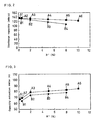
- FIG. 5 shows the relationship between the ratio R 2 of A1 and a discharge capacity at the first cycle.
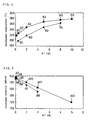
- FIG. 6 shows the relationship between the ratio R 2 of A1 and a capacity retention ratio at the 100th cycle.
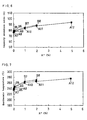
- FIG. 7 shows the relationship between the ratio R 2 of Al and a first exothermic temperature.
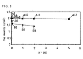
- FIG. 8 shows the relationship between the ratio R 2 of A1 and a tap density.
- each of Batteries B5 to B8 decreases in a greater amount than that of each of Batteries A7 to A12 as the ratio of A1 contained in the positive electrode active material increases.
- the positive electrode active material of each of Batteries B5 to B8 was prepared by simultaneous coprecipitation of Co, Mg and A1, sulfate ion incorporated into the active material at the time of the prepartion was left in the active material after the synthesis thereof, bringing about a capacity decrease.
- Positive electrode active materials respectively having the values: a ratio of the number of moles of M 1 to the total number of moles of Li, Co, M 1 and M 2 which were contained in a positive electrode active material defined as R 1 ; a ratio of the number of moles of M 2 to the total number of moles defined as R 2 , which are shown in Table 3, were prepared, and using these positive electrode active materials, Batteries A13 to A17 of Examples and Batteries B9 to B13 of Comparative Examples were fabricated. Mg was employed here as M 1 , and Ca, Ba, Sr, Y or Zr as M 2 .
- Positive electrode active materials to be used for Batteries A13 to A17 were synthesized in the same manner as for Battery A1 of Example, except that the ratio R 1 of Mg was fixed to be 2%, and that in the step B, calcium hydroxide, barium hydroxide, strontium hydroxide, yttrium hydroxide or zirconium nitrate was used in place of aluminum hydroxide, and the ratio R 2 of Ca, Ba, Sr, Y or Zr was fixed to be 0.5%.
- Positive electrode active materials to be used for Batteries B9 to B13 were synthesized in the same manner as for Battery B1 of Comparative Example except that the ratio R 1 of Mg was fixed to be 2%, calcium hydroxide, barium hydroxide, strontium hydroxide, yttrium hydroxide or zirconium nitrate was used in place of aluminum hydroxide, and the ratio R 2 of Ca, Ba, Sr, Y or Zr was fixed to be 0.5%.
- Example 3 Using the prescribed positive electrode, a similar rectangular non-aqueous electrolyte secondary battery to that in Example 1 was fabricated and then evaluated in the same manner as in Example 1. The results are shown in Table 3.
- Batteries A13 to A17 have greater capacities, higher capacity retention ratios and more excellent thermal stabilities than Batteries B9 to B13. Such a result is presumably attributed to the fact that: in Batteries B9 to B13, Mg is distributed more in the surface portion of the positive electrode active materials and an unreacted Mg compound tends to remain; in Batteries A13 to A17, Mg is uniformly distributed in the positive electrode active material.
- Positive electrode active materials respectively having the values: a ratio of the number of moles of M 1 to the total number of moles of Li, Co, M 1 and M 2 which were contained in a positive electrode active material defined as R 1 ; and a ratio of the number of moles of M 2 to the total number of moles defined as R 2 , which are shown in Table 4, were prepared, and using these positive electrode active materials, Batteries A18 to A19 of Examples and Batteries B14 to B15 of Comparative Examples were fabricated. Cu or Zn was employed here as M 1 , and Al as M 2 .
- Positive electrode active materials to be used for Batteries A18 to A19 were synthesized in the same manner as for Battery A3 of Example, except that in the step A, copper sulfate or zinc sulfate was used in place of magnesium sulfate.
- Positive electrode active materials to be used for Batteries B14 to B15 were synthesized in the same manner as for Battery B2 of Comparative Example, except that copper nitrate or zinc nitrate was used in place of magnesium nitrate.
- Example 4 Using the prescribed positive electrode, a similar rectangular non-aqueous electrolyte secondary battery to that in Example 1 was fabricated and then evaluated in the same manner as in Example 1. The results are shown in Table 4.
- Batteries A18 to A19 have greater capacities, higher capacity retention ratios and more excellent thermal stabilities than Batteries B14 to B15, as in Example 1. Such a result is presumably attributed to the fact that: in Batteries B14 to B15, Cu or Zn is distributed more in the surface portion of the positive electrode active materials and an unreacted Cu or Zn compound tends to remain; in Batteries A18 to A19, Cu or Zn is uniformly distributed in the positive electrode active material.
- Positive electrode active materials respectively having the values: a ratio of the number of moles of M 1 to the total number of moles of Li, Co, M 1 and M 2 which were contained in a positive electrode active material defined as R 1 ; and a ratio of the number of moles of M 2 to the total number of moles defined as R 2 , which are shown in Table 5, were prepared, and using these positive electrode active materials, Batteries A20 to A21 of Examples and Batteries B16 to B17 of Comparative Examples were fabricated. Mg and Al were employed here as M 1 and M 2 , respectively.
- Positive electrode active material to be used for Battery A20 was synthesized in the same manner as for Battery A3 of Example, except that in the step A, Mg-containing cobalt hydroxide obtained by the coprecipitating method was used as it was in place of Mg-containing cobalt oxide.
- positive electrode active material to be used for Battery A21 was synthesized in the same manner as for Battery A3 of Example, except that cobalt carbonate in which Mg was uniformly dissolved was used in place of Mg-containing cobalt oxide.
- Positive electrode active material to be used for Battery B16 was synthesized in the same manner as for Battery B2 of Comparative Example, except that cobalt hydroxide was used in place of cobalt oxide.
- Positive electrode active material to be used for Battery B17 was synthesized in the same manner as for Battery B2 of Comparative Example, except that cobalt carbonate was used in place of cobalt oxide.
- Example 5 Using the prescribed positive electrode, a similar rectangular non-aqueous electrolyte secondary battery to that in Example 1 was fabricated and then evaluated in the same manner as in Example 1. The results are shown in Table 5.
- Batteries A20 to A21 have greater capacities, higher capacity retention ratios and more excellent thermal stabilities than Batteries B16 to B17, as in Example 1. Such a result is presumably attributed to the fact that: in Batteries B16 to B17, Mg is distributed more in the surface portion of the positive electrode active materials, and an unreacted Mg compound tends to remain; in Batteries A20 to A21, Mg is uniformly distributed in the positive electrode active material.
- Example 2 It is further revealed that a similar trend to Example 1 is observed in using Mg-containing cobalt carbonate or Mg-containing cobalt hydroxide in place of Mg-containing cobalt oxide.
Landscapes
- Chemical & Material Sciences (AREA)
- Inorganic Chemistry (AREA)
- Chemical Kinetics & Catalysis (AREA)
- Electrochemistry (AREA)
- General Chemical & Material Sciences (AREA)
- Organic Chemistry (AREA)
- Engineering & Computer Science (AREA)
- Manufacturing & Machinery (AREA)
- Materials Engineering (AREA)
- Battery Electrode And Active Subsutance (AREA)
Applications Claiming Priority (3)
| Application Number | Priority Date | Filing Date | Title |
|---|---|---|---|
| JP2002142145 | 2002-05-16 | ||
| JP2002142145 | 2002-05-16 | ||
| PCT/JP2003/005555 WO2003098722A1 (en) | 2002-05-16 | 2003-04-30 | Active material of positive electrode for nonaqueous electrolyte secondary battery and process for producing the same |
Publications (2)
| Publication Number | Publication Date |
|---|---|
| EP1505672A1 true EP1505672A1 (de) | 2005-02-09 |
| EP1505672A4 EP1505672A4 (de) | 2012-01-04 |
Family
ID=29544974
Family Applications (1)
| Application Number | Title | Priority Date | Filing Date |
|---|---|---|---|
| EP03720998A Withdrawn EP1505672A4 (de) | 2002-05-16 | 2003-04-30 | Aktivmaterial einer positivelektrode für eine sekundärbatterie mit wasserfreiem elektrolyt und prozess zu ihrer herstellung |
Country Status (5)
| Country | Link |
|---|---|
| US (1) | US7422824B2 (de) |
| EP (1) | EP1505672A4 (de) |
| KR (1) | KR100637998B1 (de) |
| CN (1) | CN1292504C (de) |
| WO (1) | WO2003098722A1 (de) |
Cited By (2)
| Publication number | Priority date | Publication date | Assignee | Title |
|---|---|---|---|---|
| EP2299524A4 (de) * | 2008-07-09 | 2011-11-02 | Sanyo Electric Co | Positiv aktives elektrodenmaterial für eine sekundärbatterie mit wasserfreiem elektrolyt, verfahren zur herstellung des positiv aktiven elektrodenmaterials für eine sekundärbatterie mit wasserfreiem elektrolyt, positive elektrode für eine sekundärbatterie mit wasserfreiem elektrolyt und sekundärbatterie mit wasserfreiem elektrolyt |
| CN110337745A (zh) * | 2017-03-31 | 2019-10-15 | 松下电器产业株式会社 | 非水电解质二次电池用正极活性物质和其制造方法 |
Families Citing this family (4)
| Publication number | Priority date | Publication date | Assignee | Title |
|---|---|---|---|---|
| JP2009259798A (ja) * | 2008-03-19 | 2009-11-05 | Panasonic Corp | 非水電解質二次電池 |
| JP5732351B2 (ja) * | 2010-09-02 | 2015-06-10 | 日本化学工業株式会社 | コバルト酸リチウムの製造方法 |
| CN110649232B (zh) * | 2018-06-27 | 2023-08-01 | 株式会社村田制作所 | 锂离子二次电池用正极活性物质 |
| CN112993260B (zh) * | 2021-05-12 | 2021-08-17 | 蜂巢能源科技有限公司 | 一种掺杂型三元前驱体、制备方法、正极材料和电池 |
Family Cites Families (16)
| Publication number | Priority date | Publication date | Assignee | Title |
|---|---|---|---|---|
| JP2547992B2 (ja) | 1986-11-08 | 1996-10-30 | 旭化成工業株式会社 | 非水系二次電池 |
| JP3162437B2 (ja) * | 1990-11-02 | 2001-04-25 | セイコーインスツルメンツ株式会社 | 非水電解質二次電池 |
| JPH1173958A (ja) | 1997-06-18 | 1999-03-16 | Sony Corp | 正極活物質の製造方法 |
| JP3691279B2 (ja) * | 1998-02-10 | 2005-09-07 | 三星エスディアイ株式会社 | リチウム二次電池用正極活物質、その製造方法、及びリチウム二次電池 |
| JP3615415B2 (ja) * | 1999-03-24 | 2005-02-02 | 三洋電機株式会社 | 非水系二次電池 |
| CN1188924C (zh) * | 1999-06-21 | 2005-02-09 | 株式会社东芝 | 二次电池用正极活性物质及制法、用其制的非水电解液二次电池、再生电子功能材料及其再生方法 |
| KR100326460B1 (ko) | 2000-02-10 | 2002-02-28 | 김순택 | 리튬 이차 전지용 양극 활물질 및 그의 제조 방법 |
| DE10014884A1 (de) * | 2000-03-24 | 2001-09-27 | Merck Patent Gmbh | Beschichtete Lithium-Mischoxid-Partikel und ein Verfahren zu deren Herstellung |
| JP2001319652A (ja) | 2000-05-11 | 2001-11-16 | Sony Corp | 正極活物質及び非水電解質電池、並びにそれらの製造方法 |
| JP4416931B2 (ja) * | 2000-09-22 | 2010-02-17 | Necエレクトロニクス株式会社 | Ebマスクの設計方法及び装置 |
| JP5034136B2 (ja) * | 2000-11-14 | 2012-09-26 | 株式会社Gsユアサ | 非水電解質二次電池用正極活物質およびそれを用いた非水電解質二次電池 |
| JP4604347B2 (ja) * | 2000-12-27 | 2011-01-05 | パナソニック株式会社 | 非水電解質二次電池用正極活物質の製造方法 |
| JP4910243B2 (ja) * | 2001-04-20 | 2012-04-04 | パナソニック株式会社 | 非水電解質二次電池 |
| US6998071B2 (en) * | 2001-08-03 | 2006-02-14 | Toda Kogyo Corporation | Cobalt oxide particles and process for producing the same, cathode active material for non-aqueous electrolyte secondary cell and process for producing the same, and non-aqueous electrolyte secondary cell |
| JP2003086181A (ja) | 2001-09-11 | 2003-03-20 | Toshiba Corp | 正極活物質およびリチウムイオン二次電池 |
| JP4271448B2 (ja) * | 2003-01-16 | 2009-06-03 | パナソニック株式会社 | 非水電解質二次電池用正極活物質 |
-
2003
- 2003-04-30 EP EP03720998A patent/EP1505672A4/de not_active Withdrawn
- 2003-04-30 CN CNB038111462A patent/CN1292504C/zh not_active Expired - Lifetime
- 2003-04-30 US US10/513,925 patent/US7422824B2/en not_active Expired - Lifetime
- 2003-04-30 WO PCT/JP2003/005555 patent/WO2003098722A1/ja not_active Ceased
- 2003-04-30 KR KR1020047018404A patent/KR100637998B1/ko not_active Expired - Lifetime
Cited By (5)
| Publication number | Priority date | Publication date | Assignee | Title |
|---|---|---|---|---|
| EP2299524A4 (de) * | 2008-07-09 | 2011-11-02 | Sanyo Electric Co | Positiv aktives elektrodenmaterial für eine sekundärbatterie mit wasserfreiem elektrolyt, verfahren zur herstellung des positiv aktiven elektrodenmaterials für eine sekundärbatterie mit wasserfreiem elektrolyt, positive elektrode für eine sekundärbatterie mit wasserfreiem elektrolyt und sekundärbatterie mit wasserfreiem elektrolyt |
| US8741483B2 (en) | 2008-07-09 | 2014-06-03 | Sanyo Electric Co., Ltd. | Positive electrode active material for non-aqueous electrolyte secondary battery having rare earth hydroxide and/or oxyhydroxide |
| US9929401B2 (en) | 2008-07-09 | 2018-03-27 | Sanyo Electric Co., Ltd. | Positive electrode active material for non-aqueous electrolyte secondary battery having rare earth hydroxide and/or oxyhydroxide |
| CN110337745A (zh) * | 2017-03-31 | 2019-10-15 | 松下电器产业株式会社 | 非水电解质二次电池用正极活性物质和其制造方法 |
| CN110337745B (zh) * | 2017-03-31 | 2024-03-19 | 松下控股株式会社 | 非水电解质二次电池用正极活性物质和其制造方法 |
Also Published As
| Publication number | Publication date |
|---|---|
| US20050221183A1 (en) | 2005-10-06 |
| EP1505672A4 (de) | 2012-01-04 |
| KR20050003458A (ko) | 2005-01-10 |
| US7422824B2 (en) | 2008-09-09 |
| KR100637998B1 (ko) | 2006-10-23 |
| WO2003098722A1 (en) | 2003-11-27 |
| CN1292504C (zh) | 2006-12-27 |
| CN1653632A (zh) | 2005-08-10 |
Similar Documents
| Publication | Publication Date | Title |
|---|---|---|
| CN100342566C (zh) | 制备用于锂二次电池的活性材料的方法 | |
| CN1263182C (zh) | 用于可充电锂电池的正电极活性材料及其制备方法 | |
| CN1181580C (zh) | 可充电锂电池的正极活性材料组合物及其使用该组合物制备正极的方法 | |
| US20250174648A1 (en) | Ternary positive electrode material for lithium-ion battery and preparation method therefor | |
| JP4000041B2 (ja) | リチウム二次電池用正極活物質 | |
| US8999578B2 (en) | Positive electrode active materials for lithium secondary battery, method for preparing the same and lithium secondary battery comprising the same | |
| JP3637344B2 (ja) | 非水電解質二次電池用正極活物質およびその製造方法 | |
| JP2007515366A (ja) | リチウムイオン電池のカソード材料で使用するためのリチウム−ニッケル−コバルト−マンガン混合金属酸化物の固相合成 | |
| KR20150100406A (ko) | 양극 활물질, 그 제조방법, 이를 포함하는 리튬 이차 전지용 양극 및 이를 채용한 리튬 이차 전지 | |
| JP2013093332A (ja) | リチウム二次電池用正極活物質及びその製造方法 | |
| EP1935850A2 (de) | Zusammensetzung für negative Elektroden und wiederaufladbare nicht-wässrige Batterie diese enthaltend | |
| WO2021251416A1 (ja) | リチウムイオン二次電池用正極活物質、その製造方法、およびリチウムイオン二次電池 | |
| US7422824B2 (en) | Active material of positive electrode for nonaqueous electrolyte secondary battery and process for producing the same | |
| US20200136142A1 (en) | Active material for electrode and method of manufacturing thereof | |
| JP4703111B2 (ja) | 非水電解質二次電池 | |
| JP2002260660A (ja) | 非水系電解質二次電池用正極活物質およびその製造方法 | |
| JP3487941B2 (ja) | 非水電解液電池用正極活物質の製造方法 | |
| JP2003123750A (ja) | 非水系電解質二次電池用正極活物質およびその製造方法 | |
| JP3593322B2 (ja) | リチウム二次電池用コバルト酸リチウム系正極活物質 | |
| JP2005243536A (ja) | 非水電解質二次電池用正極活物質およびその製造方法 | |
| US7829223B1 (en) | Process for preparing lithium ion cathode material | |
| JP2002308628A (ja) | スピネル型マンガン酸リチウム | |
| JP5585913B2 (ja) | Cuを含有する二次電池用正極材料の製造方法、二次電池用正極材料の製造方法および二次電池用正極材料 | |
| JP2024074551A (ja) | リチウム金属複合酸化物の製造方法 | |
| JP2026510526A (ja) | ナトリウム二次電池用正極活物質、その製造方法およびこれを含むナトリウム二次電池 |
Legal Events
| Date | Code | Title | Description |
|---|---|---|---|
| PUAI | Public reference made under article 153(3) epc to a published international application that has entered the european phase |
Free format text: ORIGINAL CODE: 0009012 |
|
| 17P | Request for examination filed |
Effective date: 20041109 |
|
| AK | Designated contracting states |
Kind code of ref document: A1 Designated state(s): AT BE BG CH CY CZ DE DK EE ES FI FR GB GR HU IE IT LI LU MC NL PT RO SE SI SK TR |
|
| RBV | Designated contracting states (corrected) |
Designated state(s): BE DE FR |
|
| RAP1 | Party data changed (applicant data changed or rights of an application transferred) |
Owner name: PANASONIC CORPORATION |
|
| A4 | Supplementary search report drawn up and despatched |
Effective date: 20111207 |
|
| 17Q | First examination report despatched |
Effective date: 20121024 |
|
| STAA | Information on the status of an ep patent application or granted ep patent |
Free format text: STATUS: THE APPLICATION IS DEEMED TO BE WITHDRAWN |
|
| 18D | Application deemed to be withdrawn |
Effective date: 20130226 |