EP1505925B1 - Seringue a double utilisation - Google Patents
Seringue a double utilisation Download PDFInfo
- Publication number
- EP1505925B1 EP1505925B1 EP03750060A EP03750060A EP1505925B1 EP 1505925 B1 EP1505925 B1 EP 1505925B1 EP 03750060 A EP03750060 A EP 03750060A EP 03750060 A EP03750060 A EP 03750060A EP 1505925 B1 EP1505925 B1 EP 1505925B1
- Authority
- EP
- European Patent Office
- Prior art keywords
- syringe
- straw
- plunger
- guide member
- tubular body
- Prior art date
- Legal status (The legal status is an assumption and is not a legal conclusion. Google has not performed a legal analysis and makes no representation as to the accuracy of the status listed.)
- Expired - Lifetime
Links
Images


Classifications
-
- A—HUMAN NECESSITIES
- A61—MEDICAL OR VETERINARY SCIENCE; HYGIENE
- A61D—VETERINARY INSTRUMENTS, IMPLEMENTS, TOOLS, OR METHODS
- A61D19/00—Instruments or methods for reproduction or fertilisation
- A61D19/02—Instruments or methods for reproduction or fertilisation for artificial insemination
- A61D19/027—Devices for injecting semen into animals, e.g. syringes, guns, probes
-
- A—HUMAN NECESSITIES
- A61—MEDICAL OR VETERINARY SCIENCE; HYGIENE
- A61M—DEVICES FOR INTRODUCING MEDIA INTO, OR ONTO, THE BODY; DEVICES FOR TRANSDUCING BODY MEDIA OR FOR TAKING MEDIA FROM THE BODY; DEVICES FOR PRODUCING OR ENDING SLEEP OR STUPOR
- A61M37/00—Other apparatus for introducing media into the body; Percutany, i.e. introducing medicines into the body by diffusion through the skin
Definitions
- the present invention relates to injection devices, and more specifically to syringes or guns used to penetrate a uterus to transfer medicines, artificially inseminate animals, or transfer embryos.
- the syringe comprises a tubular body adapted to receive a container holding the biological material to be injected into the animal.
- the body and container can be inserted into the animal and the material is expelled from the container by a push-rod or plunger slidably insertable into the body and the container.
- a flexible sheath can be removably positioned around the body to prevent contact of the internal fluids of the animal with the body of the gun. After each use, the sheath can be removed from around the body of the syringe and discarded, allowing a new, sterile sheath to be placed around the syringe.
- the material When injecting material from this type of syringe in order to, for example, artificially inseminate a domestic animal, the material is normally contained within a plastic straw, such as that disclosed in U.S. Patent Nos. 4,478,261 and 5,190,880.
- the straw is generally a plastic tubular structure that is sealed at one end by a pair of plugs and sealed at the other end with ultrasound. These seals retain the material within the straw.
- the ultrasound sealed end is first severed from the remainder of the straw.
- the end of the straw containing the plug pair is then inserted into and engaged by the body of the syringe.
- the straw is held in this position by the sheath placed around the body.
- the plunger When properly positioned, the plunger is inserted into the body and into the straw such that the plug is contacted and urged along the length of straw by the plunger to expel the material from within the straw out the opposite end.
- the straws come mainly in two sizes, a smaller diameter straw having a volume of approximately one quarter cubic centimeter (1/4 cc), and a larger diameter straw having a volume of approximately one half cubic centimeter (1/2 cc).
- the gun or syringe in order to effectively discharge the material from within a particular diameter straw, the gun or syringe must be compatible with the diameter of the straw in which the material is contained. Due to the different sizes of the straws available, on many occasions it is necessary for an individual conducting such procedures to change the type of syringe being used in order to accommodate the size of the straw containing the biological material to be injected. This is undesirable as it is inconvenient to constantly switch between syringes when utilizing straws of different sizes.
- an injecting syringe was developed that was capable of accommodating straws of multiple sizes.
- This syringe is disclosed in U.S. Patent No. 4,173,227 and includes a tubular body defining an internal, axial cavity separated into two halves, each having a different diameter, by a tubular insert positioned within the body. Each half is capable of receiving and retaining a straw having a specific diameter, such that the injecting syringe can utilize straws having either diameter.
- the syringe must be partially disassembled in order to reverse the configuration of the body, thereby switching the ejection or outlet end of the body from one end to the other.
- the syringe By having to disassemble and reverse the configuration of the syringe, it is often the case that leaks occur between the reassembled elements of the syringe, such that some or all of the biological material that was to be injected is lost before it can be used.
- having to repeatedly turn the syringe around is a nuisance.
- an injecting syringe that is capable of accommodating straws having different diameters but does not require disassembling and/or altering the syringe to prevent the material from leaking out of the syringe.
- German patent DE 43 09 808 Cl discloses a syringe for artificially inseminating animals which syringe has a tubular body with a tapered section being adapted to abut a smaller diameter straw as well as a larger diameter straw.
- the tapered portion is integrally formed with the remainder of the tubular body thus complicating the process of manufacturing the tubular body.
- One preferred embodiment of the present invention is an injecting gun or syringe for artificially impregnating domestic animals that enables biological material-containing straws of different diameters to be utilized with the syringe.
- the injecting syringe includes a tubular body that defines an axial passage extending therethrough and includes a head fixedly attached at one end.
- the tubular body includes a guide member disposed within the passage that serves to properly position and retain the straws inserted into the passage opposite the head.
- the guide member includes a stop that engages straws having a larger diameter. The stop encircles a recess that is dimensioned to receive and retain straws contacting the guide member that have a smaller diameter.
- the syringe also includes a push rod or plunger that is removably insertable through the head, tubular body, and guide member then into the straw to expel the biological material contained within the straw outwardly from the syringe.
- the body can also be releasably positioned within a protective sheath, which prevents the syringe from contacting any fluids of the animals with which the syringe is used. This allows the syringe to be used repeatedly on a large number of different animals without spreading disease or other medical conditions between the animals.
- the invention may be a gun assembly used to inject a material into an animal with a tubular body.
- the tubular body has a first end and a second end, an axial passage extending therethrough, and a guide member fixedly positioned within the axial passage of the body.
- the guide member has a stop engageable with a large diameter straw when inserted into the axial passage in the body through the second end, a recess extending into the guide member adjacent the stop and engageable with a small diameter straw when inserted into the passage in the body through the second end, and an axial throughbore intersecting the recess.
- the stop of the syringe may be formed by an increase in the interior thickness of the guide member from the throughbore to the one end.
- the recess may have a bore with a continuously decreasing diameter in order to prevent the straw from moving upon insertion of the plunger.
- the recess may also have a frustoconical surface with a gradually increasing thickness from the throughbore to the one end for preventing the straw from moving.
- the invention further includes a method for artificial insemination that includes providing a syringe assembly with a tubular body having a head with an axial aperture fixedly attached at one end and an open end opposite the head.
- the body may define an axial passage therethrough with a guide member fixed within the axial passage and spaced from the head.
- the guide member preferably includes a stop located opposite the head, a recess extending inwardly into the guide member from the stop, and an axial throughbore communicating with the recess.
- a plunger is also included with an elongate rod having a handle at one end. The rod is dimensioned to be insertable through the aperture in the head, the passage in the tubular body, and the throughbore in the guide member.
- the elongate straw contains an amount of a biological material and has a plug formed of a deformable material adjacent one end and an open end opposite the plug.
- the user engages the end of the straw adjacent the plug with the guide means within the body, inserts the rod through the aperture in the head into the passage within the body, and then presses the handle towards the head to urge the rod through the throughbore in the guide member and into contact with the plug in the straw to force the plug along the straw and urge the biological material out of the straw through the open end of the body.
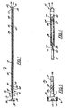
- an injecting syringe or gun constructed according to the present invention is indicated generally at 10 in Fig. 1.
- the syringe 10 includes a barrel or tubular body 12 formed of a generally rigid material, such as a metal or a plastic, and preferably stainless steel. If bent the material is able to regain its shape without a loss in performance.
- the tubular body 12 may instead be constructed of several tubes of smaller lengths with varying flexibility/rigidity.
- the tubular body 12 defines an axial passage 14 therethrough.
- the syringe 10 can also be constructed to be disposable if desired.
- a first end 15 of the body 12 is attached to a head 16 formed from a material similar to that used for the body 12 and which forms a graspable portion of the syringe 10 opposite a second end 17.
- the head 16 includes a tubular body section or tube 18 and a circular flange section 20 that can be fixedly attached to or integrally formed with one end of the body section 18.
- the flange section or flange 20 has an exterior circumferential surface 21 that can be knurled, pebbled, pitted, or otherwise altered to allow the flange 20 to be gripped more easily.
- the tube 18 preferably includes a first or reduced diameter section 22 that is insertable into the first end 15 of the tubular body 12. Because it is formed of a generally rigid material similar to that used for the body 12, the reduced diameter section 22 can be secured within the tubular body 12 by any suitable means, such as by an adhesive or by laser welding the reduced diameter section 22 to the interior of the body 12.
- the tube 18 preferably includes a second or enlarged diameter section 24 extending between the tube 18 and the flange 20.
- the head 16 also preferably defines an axial passage 26 that extends completely through the head 16 beginning at an aperture 19 through the flange 20 to the reduced diameter section 22 and is aligned with the passage 14 extending through the tubular body 12.
- Figs. 1, 7, and 10 show varied embodiments of syringe 10 with respect to tube 18, each of which represent different fastening structures 71 for temporarily fixing a sheath 48 on syringe 10, as will be discussed in further detail herein.
- the embodiment shown in Fig. 1 features a helical ridge 68 (best seen in Fig. 5) while Fig. 7 and 10 present a tube 18 with a sloped side wall 70.
- Fig. 10 additionally shows a gripping surface 78 on side wall 70.
- the surface 78 may be ridged, studded, ribbed, grained, roughened, or otherwise textured to increase the gripping power of the side wall 70.
- Fig. 7 additionally discloses a mounting O-ring 72 located over tube 18. While the surface 78 shown in the embodiment of Fig. 10 should increase friction enough to do without an O-ring 72, one can be used if desired.
- the syringe 10 also preferably includes a push rod or plunger 28 including an elongate rod 30 and a circular knob or handle 32 attached to one end of the rod 30 by any suitable means, such as by an adhesive or by welding.
- the handle 32 can be integrally formed with the rod 30 (see, e.g., Fig. 11).
- the rod 30 has a diameter less than the diameter of the passage 26 in the head 16 and the passage 14 in the body 12, such that the rod 30 can be slid into and pass through the head 16 and the tubular body 12.
- the rod 30 and handle 32 are formed of a generally rigid material similar to the body 12.
- the rod 30 has an overall length slightly greater than the combined length of the head 16 and tubular body 12, such that the rod 30 can project outwardly from the body 12 when the handle 32 of the plunger 28 is pressed against the head 16.
- the plunger 28 can also be formed from a single, unitary rod 30.
- the rod 30 is bent and spirally wound at one end in order to form an integrally connected loop 75 that functions as the handle 32.
- the formation of the plunger 28 in this manner greatly reduces the overall cost and complexity of assembling the plunger 28, as the plunger 28 includes only one part, negating any assembly of a separate handle 32 and rod 30.
- the plunger 28 can include a bend or kink 76 at a specified point along the rod 30.
- the bend 76 slides along the interior wall of the body 12 and prevents the plunger 28 from inadvertently sliding entirely out of the body 12 by contacting the end of the tube 18.
- the bend 76 is conveniently positioned far enough from the tip of the rod 30 opposite the handle 32 such that it does not interfere with the operation of the plunger 28 as it is pushed through the body 12.
- the bend 76 is spaced from the handle 32 a distance slightly longer than the length of a straw 36, and most preferably between 2 and 6 inches from the handle 32.
- the rod 30 is formed from a somewhat resilient, but generally rigid material, such as a hard plastic or preferably a spring-tempered stainless steel. More specifically, stainless steel having a tensile strength of between 250,000 psi and 290 psi is preferred in order to provide an adequately resilient rod 30.
- a marker could be provided at the location on the rod 30.
- the marker would be placed on the rod 30 such that the marker would be visible outside the body 12 when the straw 36 has not been punctured and would disappear into body 12 when the straw 36 had been opened. The marker would therefore serve as an indicator to the operator that he or she must be ready and cautious or the fluid within the straw 36 could be wasted.
- the plunger 28 can also have identifying indicia 82 etched on the handle 32 of the plunger 28 opposite the rod 30.
- the indicia 82 can be laser mark printed or etched onto the handle 32, and can indicate the owner of the syringe 10, the breed or type of livestock, or the manufacturer of the syringe 10 among other types of information.
- the indicia 82 can be etched onto the exterior of the tubular body 12, if desired.
- the tubular body 12 also includes an inner guide member 34 fixedly disposed within the passage 14 and spaced from the head 16 and forming a straw chamber 13 between the guide member 34 and the second end 17 of the body 12.
- the guide member 34 is formed of a rigid material, such as hard plastic or metal, with a stainless steel similar to the body 12 being preferred, and is generally cylindrical in shape, defining a passage 35 therethrough.
- the guide member 34 can have a cross-section other than circular, such as square, hexagonal or octagonal, for example, so long as the guide member 34 can fixedly contact the interior of the body 12 and is preferably secured in position by welding or otherwise securing the guide member 34 within the body 12.
- the guide member 34 has an exterior diameter slightly less than the diameter of the passage 14 through the tubular body 12 and an interior passage diameter slightly larger than the diameter of the rod 30.
- the guide member 34 is positioned within the body 12 between the center of the tubular body 12 and the second end 17 of the body 12 in order to form or define the straw chamber 13 between the guide member 34 and the second end 17.
- the guide member 34 is positioned within the body 12 such that the guide member 34 is spaced from the second end 17 of the tubular body 12 a distance slightly less than the overall length of a straw 36 containing the material to be injected by the syringe 10.
- the straw chamber 13 is sized to be approximately equal to the length of the straw 36.
- member 80 abuts the guide member 34 opposite the straw chamber 13. The member 80 primarily serves to reinforce tube 12.
- the guide member 34 includes a guide end 38 facing the head 16 and a stop or engagement end 40 facing the second end 17.
- the guide end 38 is formed of an outwardly tapering end section 42 of passage 35 that extends radially outwardly at an angle from the central axis of the guide member 34, which is preferably around 30°.
- the tapered end section 42 serves to contact and guide a second end of the rod 30 (i.e. the end opposite the handle 32) into and through the passage 35 within the guide member 34.
- the stop end 40 also includes an outwardly tapering end section 43 that surrounds a generally circular recess 44.
- the tapering end section 43 of the stop end 40 may be formed in several ways as shown in Figs. 8 and 9.
- the tapering end section 43 includes a flat end portion 43a extending between the exterior of the guide member 34 and the frustoconical sloping surface 43b.
- the tapering end section 43 can omit the flat end portion 43a and can comprise only the frustoconical sloping surface 43b that continuously extends between the exterior and interior of the guide member 34.
- the recess 44 extends inwardly from the stop end 40 to an annular shoulder 46 disposed within the interior of the inner guide 34 and formed around the passage 35.
- the recess 44 has a diameter approximately equal to the outer diameter of a small diameter straw 36a such that one end of the straw 36a can contact the tapered end 43 and be inserted into the recess 44 as shown in Fig. 3.
- the diameter of the stop end 40 is approximately equal to the outer diameter of the straw 36b, such that the straw 36b contacts the stop end 40 without entering the circular recess 44.
- the tubular body 12 of the syringe 10 is covered by a disposable tubular sheath 48.
- the sheath 48 is of the type disclosed in U.S. Patent No. 4,173,277, and is formed of a soft, flexible material, such as a flexible plastic, with a mounting end 50 disposed opposite an injection end 52.
- the mounting end 50 is simply an unobstructed, open end of the tubular sheath 48 into which the tubular body 12 can be inserted.
- the injection end 52 includes a rounded tapering surface 54 that extends inwardly towards the center axis of the sheath 48 in order to define a restricted diameter opening 56.
- the restricted opening 56 has a diameter less than that of the tubular body 12, the straw 36 and the rod 30, such that only the biological material contained within the straw 36 can pass through the opening 56.
- the sheath 48 also includes an insert 58 positioned within the sheath 48 and opposite the mounting end 50.
- the insert 58 is preferably formed of a semi-rigid material, such as a hard plastic, and is shaped in the form of an inwardly tapering conical cylinder with a wide end 62 positioned near the mounting end 50, and a narrow end 60 disposed opposite the wide end 62 and facing the ejection end 52.
- the insert 58 is configured to receive an open end of the straw 36, of whatever size, in order to frictionally secure the straw 36 within the sheath 48. While the insert 58 is also used to form a seal and thus prevent leakage, some operators prefer not to use it
- the straw 36 is of the type shown in U.S. Patent No. 5,190,880.
- the straw 36 preferably contains a material for artificially impregnating an animal such as semen or a fluid containing an embryo. Alternatively, the material could be a medicine.
- the straw 36 is closed at one end by a pair of plugs 66 and the opposite end sealed with ultrasound.
- the plugs 66 are preferably formed of polyvinyl alcohol powder and two cotton wads, which retain the powder in place between the wads, to retain the biological material within the straw 36.
- the straw 36 is cut to form an open end 64 at the ultrasound sealed end.
- the straw 36 is engaged with the insert 58 by inserting the open end 64 of the straw 36 into the mounting end 50 of the sheath 48 until the open end 64 contacts the insert 58 (see Fig. 6).
- the straw 36 is then pushed into the insert 58 until the open end 64 is frictionally engaged within the insert 58.
- the straw 36 can be inserted into the straw chamber 13 of the tubular body 12.
- the mounting end 50 of the sheath 48 is positioned around the tubular body 12.
- the sheath 48 is then slid upwardly along the tubular body 12 until the mounting end 50 is positioned around the head 16. This action also allows the open end 64 of the straw 36 to frictionally engage with the insert 58. While the sheath 48 is pushed upwardly around the tubular body 12, the second end 17 of the tubular body 12 surrounds the straw 36 and contacts the insert 58, urging the insert 58 and straw 36 along the sheath 48 towards the injection end 52.
- a 1 ⁇ 4 cc straw will seat nearly automatically.
- the straw should extend approximately 1 ⁇ 2 inches from the body. Turning the straw one-quarter turn will ensure the straw is properly seated.
- the straw 36 is maintained in engagement with the insert 58 by the engagement of the straw 36 with the guide member 34 disposed within the tubular body 12.
- the sheath 48 can also be used without the insert 58 to secure the straw 36 within the tubular body 12, against the guide member 34, as shown in Fig. 7.
- the open end 64 of the straw 36 and the narrow opening 60 in the insert 58 are aligned with the restricted opening 56 in the injection end 52.
- the sheath 48 can be secured in this position about the tubular body 12 by the frictional engagement of the mounting end 50 of the sheath 48 with a helical ridge 68 disposed on the tube 18 of the head 16 (shown in Fig. 5).
- the tube 18 can be formed to have a sloped side wall 70 that flares outwardly from the tubular body 12 to the flange 20, thereby increasing the diameter of the tube 18 from the body 12 to the flange 20.
- the mounting end 50 can also be cut to form a slit (not shown) that extends generally parallel to the axis of the sheath 48 to enable the mounting end 50 to expand as the body 12 is inserted.
- a slit (not shown) that extends generally parallel to the axis of the sheath 48 to enable the mounting end 50 to expand as the body 12 is inserted.
- the mounting end 50 of the sheath 48 splits along the cut in the sheath 48 to accommodate the increase in diameter of the tube 18 as the mounting end 50 is pushed along the tube 18.
- a mounting O-ring 72 having a central opening 74 may be placed around the sheath 48 at the injection end 52 and slid upwardly along the sheath 48 towards the mounting end 50 to frictionally engage the mounting end 50 of the sheath 48 between the O-ring 72 and the head 16 (as best seen in Fig. 10).
- the sloped side wall 70 of the tube 18 may also be serrated, grooved or ridged to form a gripping surface 78 that enhances the engagement of the sheath 48 between the sloped side wall 70 of the tube 18 and the O-ring 72.
- the gripping surface 78 includes a spiral ridge that engages the sheath 48 and O-ring 72 (as best seen in Fig. 10).
- the engagement of the sheath 48 around the tube 18 may also be enhanced by roughening the material forming the sheath 48 or otherwise deforming the end of the sheath 48 positioned around the tube 18, such as by adding a spiral groove (not shown) complementary to the mounting end 50 of the sheath 48.
- the rod 30 of the plunger 28 can be inserted through the head 16 into the passage 14.
- the rod 30 passes through the guide member 34 and into closed end 65 of the straw 36.
- the rod 30 contacts the plug 66 within the closed end 65, pressing the plug 66 along the length of the straw 36 and ejecting the material contained within the straw 36 outwardly from the tubular body 12 through the restricted opening 56 in the sheath 48.
- the plunger 28 is withdrawn from the body 12 such that the sheath 48 and straw 36 can be removed from the tubular body 12 and discarded, allowing another straw 36 and sheath 48 to be mounted to the syringe 10 for a successive use of the syringe 10.
- the individual components need not be formed in the disclosed shapes, or assembled in the disclosed configuration, but could be provided in virtually any shape, and assembled in virtually any configuration.
- the plunger, the chamber, and/or the sheath are described herein as physically separate modules, it will be manifest that such elements may be partially or fully integrated components of the device.
Landscapes
- Life Sciences & Earth Sciences (AREA)
- Health & Medical Sciences (AREA)
- Veterinary Medicine (AREA)
- Wood Science & Technology (AREA)
- Engineering & Computer Science (AREA)
- Reproductive Health (AREA)
- Animal Husbandry (AREA)
- Zoology (AREA)
- Animal Behavior & Ethology (AREA)
- General Health & Medical Sciences (AREA)
- Public Health (AREA)
- Infusion, Injection, And Reservoir Apparatuses (AREA)
- Medicinal Preparation (AREA)
- Medicines Containing Plant Substances (AREA)
Claims (28)
- Seringue (10) pour la fécondation artificielle des animaux, la seringue (10) comportant :a) un corps tubulaire (12) qui est formé à partir d'un matériau rigide dans son ensemble définissant un passage axial (14) à travers le corps (12) et qui a une première extrémité (15) et une deuxième extrémité (17) ;b) un piston (28) apte à être inséré dans le corps (12) ; etc) un élément de guidage (34) disposé au sein du passage axial (14) dans le corps (12), l'élément de guidage (34) ayant une longueur axiale inférieure à celle du corps tubulaire (12) et comprenant une butée (40) à une extrémité, la butée (40) destinée à arriver en butée contre une paille (36b) présentant un premier diamètre et contenant un matériau biologique insérée dans le passage axial (14) dans le corps (12) à la deuxième extrémité (17), un évidement (44) s'étendant vers l'intérieur à partir de la butée (40), l'évidement (44) destiné à venir en butée contre une paille d'un deuxième diamètre (36a) contenant un matériau biologique insérée dans le passage axial (14) dans le corps (12) à la deuxième extrémité (17) et un trou traversant axial (35) communiquant avec l'évidement dans lequel le piston (28) peut être inséré.
- Seringue (10) selon la revendication 1, caractérisée en ce que l'élément de guidage (34) est fixement attaché au corps (12).
- Seringue (10) selon la revendication 1, caractérisée en ce que l'élément de guidage (34) comprend une extrémité de guidage (38) présentant, en face de la butée (40), une surface de guidage (42) allant s'amincissant, cette surface de guidage arrivant en contact avec le piston (28) et alignant celui-ci avec le trou traversant axial (35) lorsqu'on enfonce le piston (28) en direction d'une paille (36a), (36b).
- Seringue (10) selon la revendication 1, caractérisée en ce que l'élément de guidage (34) a une section transversale à peu près égale à la section transversale du passage axial (14).
- Seringue selon la revendication 1, du type comportant par ailleurs :a) une gaine jetable (48) amovible placée autour du corps (12), la gaine (48) ayant une extrémité de montage (50) adjacente à la première extrémité (15), une extrémité restreinte (52) située à la deuxième extrémité (17) et un élément (58) d'engagement de la paille disposé à l'intérieur de la gaine (48) entre l'extrémité de montage (50) et l'extrémité restreinte (52) ; etb) une structure de fixation (71) utilisée pour assujettir, par l'intermédiaire d'une liaison par friction réversible, l'extrémité de montage (50) de la gaine (48) à la première extrémité (15).
- Seringue selon la revendication 1, caractérisée en ce que l'évidement (44) comprend un épaulement annulaire (46) susceptible de coopérer avec la paille (36a) de petit diamètre ; et en ce que l'élément de guidage (34) est distant de la première extrémité (15).
- Seringue selon la revendication 1, caractérisée en ce que la butée (40) comprend une surface (43b) qui s'incline vers l'extérieur et est adaptée pour encourager la coopération de l'évidement (44) avec la paille (36a) de petit diamètre.
- Seringue selon la revendication 1, caractérisée en ce que l'élément de guidage (34) comprend, en face de la butée (40), une extrémité amincie (42) qui aligne la tige (30) avec le trou traversant axial (35) dans l'élément de guidage (34).
- Seringue selon la revendication 5, caractérisée en ce que la structure de fixation (71) est un joint torique (72).
- Seringue selon la revendication 1, du type comportant par ailleurs une structure de fixation (71) présentant une surface de préhension.
- Seringue selon la revendication 10, caractérisée en ce que la surface de préhension (78) est une saillie hélicoïdale.
- Seringue selon la revendication 1, caractérisée en ce que la butée (40) est formée par une augmentation de l'épaisseur interne de l'élément de guidage (34) depuis le trou traversant (35) jusqu'à la section d'extrémité (43).
- Seringue selon la revendication 1, caractérisée en ce que l'évidement (44) a un diamètre décroissant en continu afin d'empêcher la paille (36) de bouger lors de l'insertion du piston (28).
- Seringue selon la revendication 1, caractérisée en ce que l'évidement (44) est tronconique et augmente graduellement en épaisseur depuis le trou traversant (35) jusqu'à la section d'extrémité (43) afin d'empêcher la paille (36) de bouger.
- Seringue selon la revendication 1, du type comportant par ailleurs une tête (16) à la première extrémité (15) du corps tubulaire (12), la tête (16) comprenant une portion de tube (18) présentant une surface de préhension (78) destinée à coopérer à frottement avec une gaine (48) apte à être placée autour du corps tubulaire (12).
- Seringue selon la revendication 1, caractérisée en ce que le piston (28) comprend un poussoir (32) formé d'un seul tenant avec le piston (28).
- Seringue selon la revendication 16, caractérisée en ce que le poussoir (32), solidaire du piston, est en forme de boucle.
- Seringue selon la revendication 1, caractérisée en ce que le piston (28) est réalisé en acier à ressort inoxydable trempé.
- Seringue selon la revendication 1, du type comportant par ailleurs un repère disposé sur le piston et destiné à indiquer commodément le bon emplacement de la paille à l'intérieur du corps tubulaire.
- Seringue selon la revendication 1, caractérisée en ce que la butée (40) comprend, à la section d'extrémité (43), une portion d'extrémité plate (43a) destinée à arrêter la paille (36).
- Seringue selon la revendication 1, caractérisée en ce qu'une partie de la seringue (10) comprend une ou plusieurs marques d'identification (82) réalisées au laser.
- Seringue selon la revendication 1, caractérisée en ce que l'extérieur du corps tubulaire (12) porte au moins une marque (82) réalisée au laser.
- Seringue selon la revendication 1, caractérisée en ce que le poussoir (32) porte au moins une marque (82) réalisée au laser.
- Seringue selon la revendication 23, caractérisée en ce que la marque (82) est spécifique au propriétaire de la seringue (10).
- Seringue selon la revendication 23, caractérisée en ce que la marque (82) est spécifique au fabricant de la seringue (10).
- Seringue selon la revendication 1, caractérisée en ce que la tige (30) du piston (28) comprend une courbure (76) servant à retenir le piston (28) à l'intérieur du corps tubulaire (12) tout en permettant sa libération.
- Seringue selon la revendication 26, caractérisée en ce que le piston (28) comprend un poussoir (32) sur un côté du piston (28) et que la courbure (76) est éloignée du poussoir (32) d'une distance légèrement plus longue que la longueur de la paille (36) de sorte que la courbure (76) ne perturbe pas le fonctionnement de la seringue (10) quand la courbure (76) arrive en contact avec le corps tubulaire (12).
- Seringue selon la revendication 27, caractérisée en ce que la courbure (76) est située à une distance comprise entre 2 et 6 pouces du poussoir (32).
Applications Claiming Priority (3)
| Application Number | Priority Date | Filing Date | Title |
|---|---|---|---|
| US143615 | 1988-01-11 | ||
| US10/143,615 US7241261B2 (en) | 2002-05-10 | 2002-05-10 | Dual use syringe |
| PCT/US2003/013990 WO2003094777A1 (fr) | 2002-05-10 | 2003-05-06 | Seringue a double utilisation |
Publications (2)
| Publication Number | Publication Date |
|---|---|
| EP1505925A1 EP1505925A1 (fr) | 2005-02-16 |
| EP1505925B1 true EP1505925B1 (fr) | 2006-06-28 |
Family
ID=29400171
Family Applications (1)
| Application Number | Title | Priority Date | Filing Date |
|---|---|---|---|
| EP03750060A Expired - Lifetime EP1505925B1 (fr) | 2002-05-10 | 2003-05-06 | Seringue a double utilisation |
Country Status (10)
| Country | Link |
|---|---|
| US (1) | US7241261B2 (fr) |
| EP (1) | EP1505925B1 (fr) |
| AT (1) | ATE331483T1 (fr) |
| AU (1) | AU2003251295A1 (fr) |
| CA (1) | CA2481105C (fr) |
| DE (1) | DE60306516T2 (fr) |
| DK (1) | DK1505925T3 (fr) |
| ES (1) | ES2268405T3 (fr) |
| MX (1) | MXPA04011109A (fr) |
| WO (1) | WO2003094777A1 (fr) |
Families Citing this family (12)
| Publication number | Priority date | Publication date | Assignee | Title |
|---|---|---|---|---|
| JP2005055718A (ja) * | 2003-08-05 | 2005-03-03 | Oki Electric Cable Co Ltd | 光スイッチ素子 |
| US7344492B2 (en) * | 2006-04-28 | 2008-03-18 | Ainley Jr Frank | Animal insemination sheath |
| US8323178B2 (en) * | 2006-04-28 | 2012-12-04 | Ainley Jr Frank | Animal insemination sheath and methods of use |
| ES2348528B1 (es) | 2008-09-26 | 2011-09-28 | Universidad De Murcia | Dispositivo y procedimiento de introduccion u obtencion de un fluido con gametos, embriones o cualquier otro tipo de solucion del interior del oviducto de una cerda. |
| EP2353544A1 (fr) * | 2008-10-07 | 2011-08-10 | Marco Antonio Hidalgo-Mendoza | Dispositif amélioré pour l'insémination artificielle d'ovins, de caprins, de cervidés et/ou d'animaux domestiques et sauvages |
| CN102481159B (zh) * | 2009-05-18 | 2015-06-17 | 斯托克Ib2C有限公司 | 人工授精 |
| WO2011068544A1 (fr) | 2009-12-04 | 2011-06-09 | Becton, Dickinson And Company | Cartouche pour contenir et distribuer un médicament |
| JP6218165B2 (ja) * | 2012-05-22 | 2017-10-25 | 株式会社ヤマネテック | 受精卵・精子注入器 |
| CN103932817B (zh) * | 2014-04-16 | 2015-11-18 | 内蒙古赛科星繁育生物技术(集团)股份有限公司 | 智能型奶牛/肉牛多功能输精枪 |
| US10182896B2 (en) | 2016-03-08 | 2019-01-22 | Frank Ainley | Animal insemination sheath and methods of use |
| US11103336B2 (en) | 2016-03-08 | 2021-08-31 | Frank Ainley | Animal insemination and in-vitro fertilization sheath, cap and methods of use |
| CN114366380A (zh) * | 2022-01-14 | 2022-04-19 | 李树平 | 一种新型输精枪套管组件 |
Family Cites Families (23)
| Publication number | Priority date | Publication date | Assignee | Title |
|---|---|---|---|---|
| NL248080A (fr) | 1959-02-04 | |||
| US3160156A (en) * | 1961-01-16 | 1964-12-08 | Mattox And Moore Inc | Artificial insemination device |
| FR1467943A (fr) * | 1965-12-23 | 1967-02-03 | Instrument perfectionné pour l'insémination artificielle | |
| US3910275A (en) | 1969-05-15 | 1975-10-07 | Victor Stephen Babey | Artificial insemination device |
| US3744493A (en) * | 1972-01-10 | 1973-07-10 | Syntex Corp | Implanter having an improved cartridge ejector |
| NL175495C (nl) * | 1974-10-31 | 1984-11-16 | Duphar Int Res | Houder voor een injectiepatroon. |
| DE2729428C3 (de) * | 1976-07-13 | 1980-10-02 | Robert Emile Justin Cassou | Injektionspistole für Tiere, insbesondere für deren künstliche Besamung |
| US4261361A (en) * | 1979-10-31 | 1981-04-14 | Bertrand Cassou | Injecting syringe in particular for the artificial insemination of domestic animals |
| US4478261A (en) * | 1981-02-20 | 1984-10-23 | Bertrand Cassou | Apparatus for filling artificial insemination straws with semen |
| FR2524303A1 (fr) * | 1982-04-06 | 1983-10-07 | Cassou Robert | Gaine de protection pour pistolet d'insemination artificielle, notamment pour bovins |
| FR2525894A1 (fr) * | 1982-04-29 | 1983-11-04 | Robert Cassou | Chemise de protection contre les contaminations internes pour pistolet d'action gynecologique, notamment pour bovins |
| DE3789320T2 (de) * | 1986-07-30 | 1994-06-09 | Sumitomo Pharma | Verabreichungsinstrument zum Einführen von festen Medikamenten. |
| FR2609885B1 (fr) * | 1987-01-22 | 1989-04-14 | Cassou Robert | Instrument pour l'insemination artificielle, le transfert d'embryons ou le prelevement de liquides folliculaires chez les mammiferes |
| US4994028A (en) * | 1987-03-18 | 1991-02-19 | Endocon, Inc. | Injector for inplanting multiple pellet medicaments |
| US4865589A (en) * | 1987-04-22 | 1989-09-12 | Ludwig Simmet | Instrument for the transfer of materials such as sperm and embryos |
| FR2651793B1 (fr) * | 1989-09-14 | 1991-12-06 | Cassou Robert | Tubes ou paillettes pour la conservation cryogenique d'echantillons biologiques tels que virus, et procede de remplissage. |
| DE4309808C1 (de) | 1993-03-29 | 1994-06-09 | Egon Mueller | Universell verwendbare Besamungspistole |
| NZ266866A (en) * | 1993-06-04 | 1996-07-26 | Kwahak International Co Ltd | Artificial insemination device; piston rod slides in an elongate hollow tube and enters a hollow straw to discharge a reproductive organism |
| US5405326A (en) * | 1993-08-26 | 1995-04-11 | Habley Medical Technology Corporation | Disposable safety syringe with retractable shuttle for luer lock needle |
| ATE239425T1 (de) * | 1994-07-29 | 2003-05-15 | Olympus Optical Co | Medizinisches instrument zur benützung in kombination mit endoskopen |
| US5904697A (en) * | 1995-02-24 | 1999-05-18 | Heartport, Inc. | Devices and methods for performing a vascular anastomosis |
| JP3361778B2 (ja) | 1999-07-09 | 2003-01-07 | 社団法人家畜改良事業団 | 家畜の人工授精用精子または受精卵移植用卵子の注入器及びその操作方法 |
| US6478780B1 (en) * | 1999-12-16 | 2002-11-12 | Jack W. Shields | Sharps shield for dental and medical needs |
-
2002
- 2002-05-10 US US10/143,615 patent/US7241261B2/en not_active Expired - Lifetime
-
2003
- 2003-05-06 DE DE60306516T patent/DE60306516T2/de not_active Expired - Lifetime
- 2003-05-06 ES ES03750060T patent/ES2268405T3/es not_active Expired - Lifetime
- 2003-05-06 AU AU2003251295A patent/AU2003251295A1/en not_active Abandoned
- 2003-05-06 EP EP03750060A patent/EP1505925B1/fr not_active Expired - Lifetime
- 2003-05-06 CA CA002481105A patent/CA2481105C/fr not_active Expired - Fee Related
- 2003-05-06 AT AT03750060T patent/ATE331483T1/de not_active IP Right Cessation
- 2003-05-06 WO PCT/US2003/013990 patent/WO2003094777A1/fr not_active Ceased
- 2003-05-06 DK DK03750060T patent/DK1505925T3/da active
- 2003-05-06 MX MXPA04011109A patent/MXPA04011109A/es active IP Right Grant
Also Published As
| Publication number | Publication date |
|---|---|
| EP1505925A1 (fr) | 2005-02-16 |
| MXPA04011109A (es) | 2005-07-14 |
| WO2003094777A1 (fr) | 2003-11-20 |
| ATE331483T1 (de) | 2006-07-15 |
| DE60306516T2 (de) | 2007-08-30 |
| US20030212307A1 (en) | 2003-11-13 |
| DK1505925T3 (da) | 2006-10-23 |
| ES2268405T3 (es) | 2007-03-16 |
| CA2481105A1 (fr) | 2003-11-20 |
| US7241261B2 (en) | 2007-07-10 |
| AU2003251295A1 (en) | 2003-11-11 |
| DE60306516D1 (de) | 2006-08-10 |
| CA2481105C (fr) | 2008-04-15 |
Similar Documents
| Publication | Publication Date | Title |
|---|---|---|
| EP1505925B1 (fr) | Seringue a double utilisation | |
| US4173227A (en) | Injecting gun for animals, in particular for the artificial insemination of cattle | |
| US3757781A (en) | Tool for administering pills to animals | |
| US5902271A (en) | Low dead space, interchangeble needle syringe | |
| US4416663A (en) | Self-sterilizing hypodermic syringe | |
| AU766393B2 (en) | Syringe drench adapter for livestock | |
| FI115698B (fi) | Turvallinen injektioruisku, jossa on ulkopuolelle liitettävä ja sisäänvedettävä itse-vinoon asettuva neula | |
| US4642094A (en) | Non-surgical embryo transfer device | |
| EP2165729B1 (fr) | Dispositif d'applicateur pré-rempli | |
| BRPI0706472A2 (pt) | kit e método para montagem de um aplicador descartável, e, aplicador descartável | |
| US10675133B2 (en) | Device for the atraumatic transfer of a material or substance with a reproductive, therapeutic or diagnostic purpose into female mammals | |
| US3127894A (en) | Method of medicine administration and device therefor | |
| US3718139A (en) | Syringe | |
| US20070078408A1 (en) | Disposable safety syringe for dispensing anesthetic | |
| US4601699A (en) | Implant device | |
| AU2009303052B2 (en) | Enhanced device for the artificial insemination of sheep, goats, deer and/or domestic and wild animals | |
| GB2441430A (en) | Safety hypodermic syringe | |
| JP6263219B2 (ja) | 注入器 | |
| US10182896B2 (en) | Animal insemination sheath and methods of use | |
| CN215084067U (zh) | 阴道送药器 | |
| US11103336B2 (en) | Animal insemination and in-vitro fertilization sheath, cap and methods of use |
Legal Events
| Date | Code | Title | Description |
|---|---|---|---|
| PUAI | Public reference made under article 153(3) epc to a published international application that has entered the european phase |
Free format text: ORIGINAL CODE: 0009012 |
|
| 17P | Request for examination filed |
Effective date: 20041125 |
|
| AK | Designated contracting states |
Kind code of ref document: A1 Designated state(s): AT BE BG CH CY CZ DE DK EE ES FI FR GB GR HU IE IT LI LU MC NL PT RO SE SI SK TR |
|
| AX | Request for extension of the european patent |
Extension state: AL LT LV MK |
|
| 17Q | First examination report despatched |
Effective date: 20040628 |
|
| DAX | Request for extension of the european patent (deleted) | ||
| GRAP | Despatch of communication of intention to grant a patent |
Free format text: ORIGINAL CODE: EPIDOSNIGR1 |
|
| GRAS | Grant fee paid |
Free format text: ORIGINAL CODE: EPIDOSNIGR3 |
|
| GRAA | (expected) grant |
Free format text: ORIGINAL CODE: 0009210 |
|
| AK | Designated contracting states |
Kind code of ref document: B1 Designated state(s): AT BE BG CH CY CZ DE DK EE ES FI FR GB GR HU IE IT LI LU MC NL PT RO SE SI SK TR |
|
| PG25 | Lapsed in a contracting state [announced via postgrant information from national office to epo] |
Ref country code: IT Free format text: LAPSE BECAUSE OF FAILURE TO SUBMIT A TRANSLATION OF THE DESCRIPTION OR TO PAY THE FEE WITHIN THE PRESCRIBED TIME-LIMIT;WARNING: LAPSES OF ITALIAN PATENTS WITH EFFECTIVE DATE BEFORE 2007 MAY HAVE OCCURRED AT ANY TIME BEFORE 2007. THE CORRECT EFFECTIVE DATE MAY BE DIFFERENT FROM THE ONE RECORDED. Effective date: 20060628 Ref country code: BE Free format text: LAPSE BECAUSE OF FAILURE TO SUBMIT A TRANSLATION OF THE DESCRIPTION OR TO PAY THE FEE WITHIN THE PRESCRIBED TIME-LIMIT Effective date: 20060628 Ref country code: AT Free format text: LAPSE BECAUSE OF FAILURE TO SUBMIT A TRANSLATION OF THE DESCRIPTION OR TO PAY THE FEE WITHIN THE PRESCRIBED TIME-LIMIT Effective date: 20060628 Ref country code: CH Free format text: LAPSE BECAUSE OF FAILURE TO SUBMIT A TRANSLATION OF THE DESCRIPTION OR TO PAY THE FEE WITHIN THE PRESCRIBED TIME-LIMIT Effective date: 20060628 Ref country code: SI Free format text: LAPSE BECAUSE OF FAILURE TO SUBMIT A TRANSLATION OF THE DESCRIPTION OR TO PAY THE FEE WITHIN THE PRESCRIBED TIME-LIMIT Effective date: 20060628 Ref country code: SK Free format text: LAPSE BECAUSE OF FAILURE TO SUBMIT A TRANSLATION OF THE DESCRIPTION OR TO PAY THE FEE WITHIN THE PRESCRIBED TIME-LIMIT Effective date: 20060628 Ref country code: FI Free format text: LAPSE BECAUSE OF FAILURE TO SUBMIT A TRANSLATION OF THE DESCRIPTION OR TO PAY THE FEE WITHIN THE PRESCRIBED TIME-LIMIT Effective date: 20060628 Ref country code: RO Free format text: LAPSE BECAUSE OF FAILURE TO SUBMIT A TRANSLATION OF THE DESCRIPTION OR TO PAY THE FEE WITHIN THE PRESCRIBED TIME-LIMIT Effective date: 20060628 Ref country code: LI Free format text: LAPSE BECAUSE OF FAILURE TO SUBMIT A TRANSLATION OF THE DESCRIPTION OR TO PAY THE FEE WITHIN THE PRESCRIBED TIME-LIMIT Effective date: 20060628 Ref country code: CZ Free format text: LAPSE BECAUSE OF FAILURE TO SUBMIT A TRANSLATION OF THE DESCRIPTION OR TO PAY THE FEE WITHIN THE PRESCRIBED TIME-LIMIT Effective date: 20060628 |
|
| REG | Reference to a national code |
Ref country code: GB Ref legal event code: FG4D |
|
| REG | Reference to a national code |
Ref country code: CH Ref legal event code: EP |
|
| REG | Reference to a national code |
Ref country code: IE Ref legal event code: FG4D |
|
| REF | Corresponds to: |
Ref document number: 60306516 Country of ref document: DE Date of ref document: 20060810 Kind code of ref document: P |
|
| PG25 | Lapsed in a contracting state [announced via postgrant information from national office to epo] |
Ref country code: SE Free format text: LAPSE BECAUSE OF FAILURE TO SUBMIT A TRANSLATION OF THE DESCRIPTION OR TO PAY THE FEE WITHIN THE PRESCRIBED TIME-LIMIT Effective date: 20060928 |
|
| REG | Reference to a national code |
Ref country code: DK Ref legal event code: T3 |
|
| PG25 | Lapsed in a contracting state [announced via postgrant information from national office to epo] |
Ref country code: PT Free format text: LAPSE BECAUSE OF FAILURE TO SUBMIT A TRANSLATION OF THE DESCRIPTION OR TO PAY THE FEE WITHIN THE PRESCRIBED TIME-LIMIT Effective date: 20061128 |
|
| REG | Reference to a national code |
Ref country code: CH Ref legal event code: PL |
|
| ET | Fr: translation filed | ||
| REG | Reference to a national code |
Ref country code: ES Ref legal event code: FG2A Ref document number: 2268405 Country of ref document: ES Kind code of ref document: T3 |
|
| PLBE | No opposition filed within time limit |
Free format text: ORIGINAL CODE: 0009261 |
|
| STAA | Information on the status of an ep patent application or granted ep patent |
Free format text: STATUS: NO OPPOSITION FILED WITHIN TIME LIMIT |
|
| 26N | No opposition filed |
Effective date: 20070329 |
|
| PG25 | Lapsed in a contracting state [announced via postgrant information from national office to epo] |
Ref country code: MC Free format text: LAPSE BECAUSE OF NON-PAYMENT OF DUE FEES Effective date: 20070531 |
|
| PG25 | Lapsed in a contracting state [announced via postgrant information from national office to epo] |
Ref country code: GR Free format text: LAPSE BECAUSE OF FAILURE TO SUBMIT A TRANSLATION OF THE DESCRIPTION OR TO PAY THE FEE WITHIN THE PRESCRIBED TIME-LIMIT Effective date: 20060929 |
|
| PG25 | Lapsed in a contracting state [announced via postgrant information from national office to epo] |
Ref country code: BG Free format text: LAPSE BECAUSE OF FAILURE TO SUBMIT A TRANSLATION OF THE DESCRIPTION OR TO PAY THE FEE WITHIN THE PRESCRIBED TIME-LIMIT Effective date: 20060928 |
|
| PG25 | Lapsed in a contracting state [announced via postgrant information from national office to epo] |
Ref country code: EE Free format text: LAPSE BECAUSE OF FAILURE TO SUBMIT A TRANSLATION OF THE DESCRIPTION OR TO PAY THE FEE WITHIN THE PRESCRIBED TIME-LIMIT Effective date: 20060628 |
|
| PGFP | Annual fee paid to national office [announced via postgrant information from national office to epo] |
Ref country code: DK Payment date: 20090514 Year of fee payment: 7 Ref country code: ES Payment date: 20090605 Year of fee payment: 7 Ref country code: IE Payment date: 20090521 Year of fee payment: 7 Ref country code: NL Payment date: 20090504 Year of fee payment: 7 |
|
| PG25 | Lapsed in a contracting state [announced via postgrant information from national office to epo] |
Ref country code: LU Free format text: LAPSE BECAUSE OF NON-PAYMENT OF DUE FEES Effective date: 20070506 Ref country code: CY Free format text: LAPSE BECAUSE OF FAILURE TO SUBMIT A TRANSLATION OF THE DESCRIPTION OR TO PAY THE FEE WITHIN THE PRESCRIBED TIME-LIMIT Effective date: 20060628 |
|
| PGFP | Annual fee paid to national office [announced via postgrant information from national office to epo] |
Ref country code: IT Payment date: 20090516 Year of fee payment: 7 |
|
| PG25 | Lapsed in a contracting state [announced via postgrant information from national office to epo] |
Ref country code: TR Free format text: LAPSE BECAUSE OF FAILURE TO SUBMIT A TRANSLATION OF THE DESCRIPTION OR TO PAY THE FEE WITHIN THE PRESCRIBED TIME-LIMIT Effective date: 20060628 Ref country code: HU Free format text: LAPSE BECAUSE OF FAILURE TO SUBMIT A TRANSLATION OF THE DESCRIPTION OR TO PAY THE FEE WITHIN THE PRESCRIBED TIME-LIMIT Effective date: 20061229 |
|
| REG | Reference to a national code |
Ref country code: NL Ref legal event code: V1 Effective date: 20101201 |
|
| REG | Reference to a national code |
Ref country code: DK Ref legal event code: EBP |
|
| PG25 | Lapsed in a contracting state [announced via postgrant information from national office to epo] |
Ref country code: NL Free format text: LAPSE BECAUSE OF NON-PAYMENT OF DUE FEES Effective date: 20101201 Ref country code: IT Free format text: LAPSE BECAUSE OF NON-PAYMENT OF DUE FEES Effective date: 20100506 |
|
| PG25 | Lapsed in a contracting state [announced via postgrant information from national office to epo] |
Ref country code: DK Free format text: LAPSE BECAUSE OF NON-PAYMENT OF DUE FEES Effective date: 20100531 Ref country code: IE Free format text: LAPSE BECAUSE OF NON-PAYMENT OF DUE FEES Effective date: 20100506 |
|
| REG | Reference to a national code |
Ref country code: ES Ref legal event code: FD2A Effective date: 20110711 |
|
| PG25 | Lapsed in a contracting state [announced via postgrant information from national office to epo] |
Ref country code: ES Free format text: LAPSE BECAUSE OF NON-PAYMENT OF DUE FEES Effective date: 20110629 |
|
| PG25 | Lapsed in a contracting state [announced via postgrant information from national office to epo] |
Ref country code: ES Free format text: LAPSE BECAUSE OF NON-PAYMENT OF DUE FEES Effective date: 20100507 |
|
| PGFP | Annual fee paid to national office [announced via postgrant information from national office to epo] |
Ref country code: GB Payment date: 20120530 Year of fee payment: 10 Ref country code: FR Payment date: 20120615 Year of fee payment: 10 |
|
| PGFP | Annual fee paid to national office [announced via postgrant information from national office to epo] |
Ref country code: DE Payment date: 20120730 Year of fee payment: 10 |
|
| GBPC | Gb: european patent ceased through non-payment of renewal fee |
Effective date: 20130506 |
|
| PG25 | Lapsed in a contracting state [announced via postgrant information from national office to epo] |
Ref country code: DE Free format text: LAPSE BECAUSE OF NON-PAYMENT OF DUE FEES Effective date: 20131203 |
|
| REG | Reference to a national code |
Ref country code: DE Ref legal event code: R119 Ref document number: 60306516 Country of ref document: DE Effective date: 20131203 |
|
| REG | Reference to a national code |
Ref country code: FR Ref legal event code: ST Effective date: 20140131 |
|
| PG25 | Lapsed in a contracting state [announced via postgrant information from national office to epo] |
Ref country code: GB Free format text: LAPSE BECAUSE OF NON-PAYMENT OF DUE FEES Effective date: 20130506 |
|
| PG25 | Lapsed in a contracting state [announced via postgrant information from national office to epo] |
Ref country code: FR Free format text: LAPSE BECAUSE OF NON-PAYMENT OF DUE FEES Effective date: 20130531 |