EP1506050B1 - Procede et installation de filtrage pour separer un produit de condensation et des matieres analogues - Google Patents
Procede et installation de filtrage pour separer un produit de condensation et des matieres analogues Download PDFInfo
- Publication number
- EP1506050B1 EP1506050B1 EP02716792A EP02716792A EP1506050B1 EP 1506050 B1 EP1506050 B1 EP 1506050B1 EP 02716792 A EP02716792 A EP 02716792A EP 02716792 A EP02716792 A EP 02716792A EP 1506050 B1 EP1506050 B1 EP 1506050B1
- Authority
- EP
- European Patent Office
- Prior art keywords
- filter
- hydrophilic foam
- condensate
- air
- foam
- Prior art date
- Legal status (The legal status is an assumption and is not a legal conclusion. Google has not performed a legal analysis and makes no representation as to the accuracy of the status listed.)
- Expired - Lifetime
Links
- 238000000034 method Methods 0.000 title claims description 9
- 238000009434 installation Methods 0.000 title 1
- 239000006260 foam Substances 0.000 claims description 44
- 239000000463 material Substances 0.000 claims description 20
- 239000011148 porous material Substances 0.000 claims description 13
- OKTJSMMVPCPJKN-UHFFFAOYSA-N Carbon Chemical compound [C] OKTJSMMVPCPJKN-UHFFFAOYSA-N 0.000 claims description 12
- 230000003647 oxidation Effects 0.000 claims description 5
- 238000007254 oxidation reaction Methods 0.000 claims description 5
- 238000011144 upstream manufacturing Methods 0.000 claims 1
- 239000007788 liquid Substances 0.000 description 12
- 238000004140 cleaning Methods 0.000 description 8
- 239000000443 aerosol Substances 0.000 description 6
- 238000005406 washing Methods 0.000 description 5
- 230000000694 effects Effects 0.000 description 4
- 238000001914 filtration Methods 0.000 description 4
- 239000000470 constituent Substances 0.000 description 3
- 239000007787 solid Substances 0.000 description 3
- 239000000428 dust Substances 0.000 description 2
- 239000003995 emulsifying agent Substances 0.000 description 2
- 239000003517 fume Substances 0.000 description 2
- 238000004519 manufacturing process Methods 0.000 description 2
- 239000002245 particle Substances 0.000 description 2
- 238000011045 prefiltration Methods 0.000 description 2
- 239000000126 substance Substances 0.000 description 2
- 239000012876 carrier material Substances 0.000 description 1
- 239000012459 cleaning agent Substances 0.000 description 1
- 230000003749 cleanliness Effects 0.000 description 1
- 238000009833 condensation Methods 0.000 description 1
- 230000005494 condensation Effects 0.000 description 1
- 238000011109 contamination Methods 0.000 description 1
- 230000003670 easy-to-clean Effects 0.000 description 1
- 239000003344 environmental pollutant Substances 0.000 description 1
- 150000002148 esters Chemical class 0.000 description 1
- 239000003925 fat Substances 0.000 description 1
- 239000000835 fiber Substances 0.000 description 1
- 239000006261 foam material Substances 0.000 description 1
- 239000004519 grease Substances 0.000 description 1
- 238000010438 heat treatment Methods 0.000 description 1
- 239000012535 impurity Substances 0.000 description 1
- 239000008258 liquid foam Substances 0.000 description 1
- 231100000719 pollutant Toxicity 0.000 description 1
- 239000002244 precipitate Substances 0.000 description 1
- 238000001556 precipitation Methods 0.000 description 1
- 230000001105 regulatory effect Effects 0.000 description 1
- 239000005871 repellent Substances 0.000 description 1
- 229920006395 saturated elastomer Polymers 0.000 description 1
- 238000000926 separation method Methods 0.000 description 1
- 229910001220 stainless steel Inorganic materials 0.000 description 1
- 239000010935 stainless steel Substances 0.000 description 1
- 238000009423 ventilation Methods 0.000 description 1
- XLYOFNOQVPJJNP-UHFFFAOYSA-N water Chemical compound O XLYOFNOQVPJJNP-UHFFFAOYSA-N 0.000 description 1
Images

Classifications
-
- B—PERFORMING OPERATIONS; TRANSPORTING
- B01—PHYSICAL OR CHEMICAL PROCESSES OR APPARATUS IN GENERAL
- B01D—SEPARATION
- B01D53/00—Separation of gases or vapours; Recovering vapours of volatile solvents from gases; Chemical or biological purification of waste gases, e.g. engine exhaust gases, smoke, fumes, flue gases, aerosols
- B01D53/02—Separation of gases or vapours; Recovering vapours of volatile solvents from gases; Chemical or biological purification of waste gases, e.g. engine exhaust gases, smoke, fumes, flue gases, aerosols by adsorption, e.g. preparative gas chromatography
- B01D53/04—Separation of gases or vapours; Recovering vapours of volatile solvents from gases; Chemical or biological purification of waste gases, e.g. engine exhaust gases, smoke, fumes, flue gases, aerosols by adsorption, e.g. preparative gas chromatography with stationary adsorbents
- B01D53/0407—Constructional details of adsorbing systems
-
- B—PERFORMING OPERATIONS; TRANSPORTING
- B01—PHYSICAL OR CHEMICAL PROCESSES OR APPARATUS IN GENERAL
- B01D—SEPARATION
- B01D46/00—Filters or filtering processes specially modified for separating dispersed particles from gases or vapours
- B01D46/0027—Filters or filtering processes specially modified for separating dispersed particles from gases or vapours with additional separating or treating functions
- B01D46/003—Filters or filtering processes specially modified for separating dispersed particles from gases or vapours with additional separating or treating functions including coalescing means for the separation of liquid
-
- B—PERFORMING OPERATIONS; TRANSPORTING
- B01—PHYSICAL OR CHEMICAL PROCESSES OR APPARATUS IN GENERAL
- B01D—SEPARATION
- B01D46/00—Filters or filtering processes specially modified for separating dispersed particles from gases or vapours
- B01D46/0027—Filters or filtering processes specially modified for separating dispersed particles from gases or vapours with additional separating or treating functions
- B01D46/0036—Filters or filtering processes specially modified for separating dispersed particles from gases or vapours with additional separating or treating functions by adsorption or absorption
-
- B—PERFORMING OPERATIONS; TRANSPORTING
- B01—PHYSICAL OR CHEMICAL PROCESSES OR APPARATUS IN GENERAL
- B01D—SEPARATION
- B01D46/00—Filters or filtering processes specially modified for separating dispersed particles from gases or vapours
- B01D46/10—Particle separators, e.g. dust precipitators, using filter plates, sheets or pads having plane surfaces
- B01D46/12—Particle separators, e.g. dust precipitators, using filter plates, sheets or pads having plane surfaces in multiple arrangements
-
- B—PERFORMING OPERATIONS; TRANSPORTING
- B01—PHYSICAL OR CHEMICAL PROCESSES OR APPARATUS IN GENERAL
- B01D—SEPARATION
- B01D46/00—Filters or filtering processes specially modified for separating dispersed particles from gases or vapours
- B01D46/56—Filters or filtering processes specially modified for separating dispersed particles from gases or vapours with multiple filtering elements, characterised by their mutual disposition
- B01D46/62—Filters or filtering processes specially modified for separating dispersed particles from gases or vapours with multiple filtering elements, characterised by their mutual disposition connected in series
-
- B—PERFORMING OPERATIONS; TRANSPORTING
- B01—PHYSICAL OR CHEMICAL PROCESSES OR APPARATUS IN GENERAL
- B01D—SEPARATION
- B01D46/00—Filters or filtering processes specially modified for separating dispersed particles from gases or vapours
- B01D46/66—Regeneration of the filtering material or filter elements inside the filter
- B01D46/79—Regeneration of the filtering material or filter elements inside the filter by liquid process
-
- B—PERFORMING OPERATIONS; TRANSPORTING
- B01—PHYSICAL OR CHEMICAL PROCESSES OR APPARATUS IN GENERAL
- B01D—SEPARATION
- B01D53/00—Separation of gases or vapours; Recovering vapours of volatile solvents from gases; Chemical or biological purification of waste gases, e.g. engine exhaust gases, smoke, fumes, flue gases, aerosols
- B01D53/002—Separation of gases or vapours; Recovering vapours of volatile solvents from gases; Chemical or biological purification of waste gases, e.g. engine exhaust gases, smoke, fumes, flue gases, aerosols by condensation
-
- F—MECHANICAL ENGINEERING; LIGHTING; HEATING; WEAPONS; BLASTING
- F24—HEATING; RANGES; VENTILATING
- F24C—DOMESTIC STOVES OR RANGES ; DETAILS OF DOMESTIC STOVES OR RANGES, OF GENERAL APPLICATION
- F24C15/00—Details
- F24C15/20—Removing cooking fumes
- F24C15/2035—Arrangement or mounting of filters
-
- B—PERFORMING OPERATIONS; TRANSPORTING
- B01—PHYSICAL OR CHEMICAL PROCESSES OR APPARATUS IN GENERAL
- B01D—SEPARATION
- B01D2253/00—Adsorbents used in seperation treatment of gases and vapours
- B01D2253/10—Inorganic adsorbents
- B01D2253/102—Carbon
-
- B—PERFORMING OPERATIONS; TRANSPORTING
- B01—PHYSICAL OR CHEMICAL PROCESSES OR APPARATUS IN GENERAL
- B01D—SEPARATION
- B01D2253/00—Adsorbents used in seperation treatment of gases and vapours
- B01D2253/30—Physical properties of adsorbents
- B01D2253/34—Specific shapes
- B01D2253/342—Monoliths
-
- B—PERFORMING OPERATIONS; TRANSPORTING
- B01—PHYSICAL OR CHEMICAL PROCESSES OR APPARATUS IN GENERAL
- B01D—SEPARATION
- B01D2259/00—Type of treatment
- B01D2259/40—Further details for adsorption processes and devices
- B01D2259/40083—Regeneration of adsorbents in processes other than pressure or temperature swing adsorption
-
- B—PERFORMING OPERATIONS; TRANSPORTING
- B01—PHYSICAL OR CHEMICAL PROCESSES OR APPARATUS IN GENERAL
- B01D—SEPARATION
- B01D2259/00—Type of treatment
- B01D2259/40—Further details for adsorption processes and devices
- B01D2259/414—Further details for adsorption processes and devices using different types of adsorbents
- B01D2259/4141—Further details for adsorption processes and devices using different types of adsorbents within a single bed
- B01D2259/4145—Further details for adsorption processes and devices using different types of adsorbents within a single bed arranged in series
- B01D2259/4148—Multiple layers positioned apart from each other
-
- B—PERFORMING OPERATIONS; TRANSPORTING
- B01—PHYSICAL OR CHEMICAL PROCESSES OR APPARATUS IN GENERAL
- B01D—SEPARATION
- B01D2259/00—Type of treatment
- B01D2259/45—Gas separation or purification devices adapted for specific applications
- B01D2259/4508—Gas separation or purification devices adapted for specific applications for cleaning air in buildings
Definitions
- the invention relates to a method for separating condensate and the like from an air stream, wherein the air flow is passed through a porous filter material.
- the air flow that is conducted through often contains not only gaseous or solid substances but also a not inconsiderable proportion of condensate-forming components. Filtering out these substances and / or the condensate-forming constituents from the air stream may be necessary in order to avoid possible odor nuisance or the uncontrolled precipitation of condensate.
- the exhaust air produced in closed rooms may contain pollutants and / or cause a fire hazard in the exhaust duct.
- the condensate-forming constituents contained in the air stream in the form of vapors or aerosols preferably precipitate on surfaces which are colder than the air flow. Solid particles and dust also adhere to the moist surfaces.
- Most filter systems are therefore based on a controlled condensation on specially designed and appropriately designed surfaces.
- a mechanical filter for example a baffle separator
- the incoming exhaust air is redirected several times so strong that it contained condensate droplets hit the surface of the mechanical filter and are deposited there.
- a simple mechanical filter does not have the necessary properties for many applications, in particular to adequately separate small droplets and aerosols from the airflow passed through.
- the air flow must then be passed through additional filtering devices such as fiber filters or oxidation filters such as activated carbon filters, however, which store the condensate deposited therein and therefore need to be replaced after some time.
- Document GB-A-2 267 840 relates to a heat and moisture exchanger for patient ventilation.
- a heat and moisture-exchanging element made of hydrophilic foam is not used there to filter the air flow passed through.
- the air flow is filtered with a separately arranged filter element.
- a hydrophilic foam merely serves as a carrier material with a large surface area for an associated filter material, in particular for activated carbon.
- the filter effect of the respirator is attributed solely to the filter material connected to the foam.
- the document DE 25 30 107 A describes a filter for extractor hoods with a filter mat made of a synthetic foam, which is subsequently provided with a superficially adhering emulsifier. It can be applied to the foam mat only a small amount of the emulsifier, so that a low filter quality and at regular intervals saturation and a concomitant reduction in the filter function are to be feared.
- the object of the invention is therefore to provide a method of the type mentioned in such a way that with simple means effective separation of condensate and the like from an air stream is achieved. Even with a high amount of separated condensate cleaning of the filter system is rarely necessary and a continuous and cost-effective operation may be possible.
- This object is achieved in that the air flow is passed through an at least partially open-pore, hydrophilic foam.
- the air flow is first passed through a mechanical filter and subsequently through the at least partially open-pored, hydrophilic foam.
- the mechanical filter can be very simple and easy to clean, since it is mainly intended to deposit large drops of condensate from the airflow passed through.
- the then arranged at least partially open-pored, hydrophilic foam has only a much lower volume of condensate in the form of small droplets and aerosols from the air stream deposited. Since there are less residues in the foam due to the lower condensate volume, it only needs to be cleaned or replaced much less frequently.
- the invention also relates to a filter system for carrying out the method.
- the filter system is characterized in that the filter material used is an at least partially open-pored, hydrophilic foam.
- the hydrophilic foam can be produced inexpensively in large quantities. It is also possible to retrofit already operated filter systems later for use with this filter material.
- the partially open-pored, hydrophilic foam has a substantially reticular structure.
- a net-like structure of the hydrophilic foam can be achieved in the production of the filter material. Due to the predetermined arrangement of the pores and material surfaces, a rapid collection and drainage of the condensate liquid is promoted. At the same time, the predetermined structure ensures a filter property which remains constant over large areas of the hydrophilic foam.
- the reticular structure of the hydrophilic foam also improves its stability, so that it easily withstands the usual mechanical stresses.
- the filter material is regenerable. Does the exhaust air or supply air to be filtered have a high content of dissolved solids or Fats on, such components from the condensed liquid can easily be deposited in the hard to reach pores of the foam. With increasing service life more and more pores clog, so that the filter effect of the foam is reduced.
- the filter material can then be removed from the filter unit and, for example, washed out with the addition of cleaning agents or in an ultrasonic bath.
- the air flow is guided through a channel 1.
- the air flow must pass through an area filled with an at least partially open-pored, hydrophilic foam 2.
- the flow rate of the air flow can be controlled, for example, by a fan not shown in the figure.
- the flow rate of the air stream is expediently chosen so that on the one hand the air is carried away as quickly as possible, but on the other hand, the air flow can not entrain droplets of already deposited in the filter material condensate.
- hydrophilic foam 2 As a porous filter material, the filter effect is significantly improved. Even the finest aerosols are almost completely separated from the air stream, so that a subsequent UV oxidation or HS oxidation is possible.
- the exhaust air filter system shown in Fig. 2 shows an exhaust duct 1 ', which has a mechanical filter 3 on the side of the air inlet. A large proportion of the accumulating condensate is already deposited by the mechanical filter 3 from the exhaust air. After the mechanical filter 3, a layer of at least partially open-pored, hydrophilic foam 2 in the exhaust duct 1 'is arranged. Even small droplets and aerosols are effectively eliminated in the hydrophilic foam 2 from the passed exhaust air.
- the flow velocity of the exhaust air through the exhaust air duct 1 'and thus by the mechanical filter 3 and the at least partially porous, hydrophilic foam 2 is controlled by a fan 4, which is then mounted in the exhaust duct 1'.
- On the outlet side of the exhaust air filter system is an activated carbon filter 5, are filtered out with the entrained in the exhaust air molecules.
- Both the mechanical filter 3 and the at least partially open-pored, hydrophilic foam 2 can be cleaned regularly to wash out settling residues of the condensate.
- a device for washing 6 of both filter materials is attached between the mechanical filter 3 and the hydrophilic foam 2, a device for washing 6 of both filter materials is attached. Possibly provided with cleaning liquid can be distributed during operation of the exhaust air filtration system by the device for washing 6 in the exhaust duct 1 '. The cleaning liquid washes during the draining from the mechanical filter 3 and the partially porous, hydrophilic foam there adhering residues and runs as the separated condensate liquid through an outlet opening 7 of the exhaust duct 1 'from.
- the Zu povertyfilterstrom shown in Fig. 3 is very similar to the exhaust air filter system shown in Fig. 2. Instead of an activated carbon filter is a device for temperature control 8 in the supply air duct 1 ", with which the supplied air can be heated or cooled.
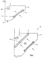
- the schematic arrangement shown in Fig. 4 shows a fume hood housing 9.
- the fume hood housing 9 is preferably made of stainless steel, to allow easy and hygienic cleaning.
- the exhaust air is sucked through a thin disc of at least partially porous, hydrophilic foam 2 into the interior of the extractor housing 9.
- the flow rate of the extracted exhaust air can be controlled by means of a suction fan 10.
- the precipitated in the hydrophilic foam 2 condensate liquid flows quickly in the filter material and is collected in a same serving as a holding device for the hydrophilic foam 2 collecting channel 11. From there, the condensate liquid can be controlled discharged through a drain 12.
- the hydrophilic foam 2 can be easily removed. Due to good filter properties, ester foam materials are especially suitable for use as filter material.
- FIG. 5 another embodiment of an extractor hood 13 is shown.
- the exhaust air is first sucked through a pre-filter 14, which is usually designed as a baffle or as a mechanical filter and also acts as a flame. Damage caused by flames or excessive heat of the behind the prefilter inside the extractor housing 9 arranged thin disc of at least partially open-pored, hydrophilic foam 2 is therefore almost impossible.
- a washing device 15 is arranged in each case. At determinable intervals or continuously can be sprayed by these washing devices 15, a cleaning liquid in the direction of the thin disc of at least partially open-pored, hydrophilic foam 2. With a clever arrangement and design of the washing devices 15, an almost complete cleaning of the entire interior of the extractor hood 13 is automated and also possible during operation.
Landscapes
- Chemical & Material Sciences (AREA)
- Chemical Kinetics & Catalysis (AREA)
- Engineering & Computer Science (AREA)
- Analytical Chemistry (AREA)
- General Chemical & Material Sciences (AREA)
- Oil, Petroleum & Natural Gas (AREA)
- Combustion & Propulsion (AREA)
- Mechanical Engineering (AREA)
- General Engineering & Computer Science (AREA)
- Filtering Of Dispersed Particles In Gases (AREA)
Claims (7)
- Procédé en vue de la séparation/du dépôt de condensat et similaires hors d'un courant d'air dans des hottes d'aspiration, le courant d'air étant conduit à travers une mousse hydrophile (2), présentant une structure réticulaire, au moins partiellement constituée de pores ouverts, qui provoque un dépôt du condensat entraîné par le courant d'air.
- Procédé selon la revendication 1, caractérisé en ce que le courant d'air est conduit tout d'abord à travers un filtre mécanique (3) et ensuite à travers la mousse hydrophile (2), au moins partiellement constituée de pores ouverts.
- Procédé selon la revendication 1, caractérisé en ce que le courant d'air est conduit, après la mousse hydrophile (2), au moins partiellement constituée de pores ouverts, à travers un filtre d'oxydation, en particulier un filtre à charbon actif (5).
- Installation à filtres dans une hotte d'aspiration en vue de l'exécution du procédé selon la revendication 1, caractérisée en ce que le matériau de filtre utilisé est une mousse hydrophile (2), présentant une structure réticulaire, au moins partiellement constituée de pores ouverts.
- Installation à filtres selon la revendication 4, caractérisée en ce que le matériau de filtre peut être régénéré.
- Installation à filtres selon la revendication 4 ou 5, caractérisée en ce que l'on dispose, avant la mousse hydrophile (2), au moins partiellement constituée de pores ouverts, en sus, un filtre mécanique (3).
- Installation à filtre selon la revendication 4, 5 ou 6, caractérisée en ce que l'on dispose, après la mousse hydrophile (2), au moins partiellement constituée de pores ouverts, un filtre d'oxydation, en particulier, un filtre à charbon actif (5).
Priority Applications (1)
| Application Number | Priority Date | Filing Date | Title |
|---|---|---|---|
| AT02716792T ATE346673T1 (de) | 2002-02-20 | 2002-02-20 | Verfahren und filteranlage zum abscheiden von kondensat und dergleichen |
Applications Claiming Priority (1)
| Application Number | Priority Date | Filing Date | Title |
|---|---|---|---|
| PCT/EP2002/001775 WO2003070355A1 (fr) | 2002-02-20 | 2002-02-20 | Procede et installation de filtrage pour separer un produit de condensation et des matieres analogues |
Publications (2)
| Publication Number | Publication Date |
|---|---|
| EP1506050A1 EP1506050A1 (fr) | 2005-02-16 |
| EP1506050B1 true EP1506050B1 (fr) | 2006-11-29 |
Family
ID=27741080
Family Applications (1)
| Application Number | Title | Priority Date | Filing Date |
|---|---|---|---|
| EP02716792A Expired - Lifetime EP1506050B1 (fr) | 2002-02-20 | 2002-02-20 | Procede et installation de filtrage pour separer un produit de condensation et des matieres analogues |
Country Status (5)
| Country | Link |
|---|---|
| EP (1) | EP1506050B1 (fr) |
| AU (1) | AU2002247727A1 (fr) |
| DE (1) | DE50208871D1 (fr) |
| DK (1) | DK1506050T3 (fr) |
| WO (1) | WO2003070355A1 (fr) |
Cited By (2)
| Publication number | Priority date | Publication date | Assignee | Title |
|---|---|---|---|---|
| DE102007042284A1 (de) | 2007-06-07 | 2008-12-11 | Convotherm Elektrogeräte GmbH | Rezirkulationshaube |
| DE202015104362U1 (de) * | 2015-08-18 | 2016-11-21 | MKN Maschinenfabrik Kurt Neubauer GmbH & Co. KG | Dunstabzugshaube für eine Fritteuse |
Families Citing this family (10)
| Publication number | Priority date | Publication date | Assignee | Title |
|---|---|---|---|---|
| CA2494814C (fr) * | 2002-08-16 | 2010-09-28 | Kim Lui So | Systeme et procede d'evacuation autonettoyant |
| DE102007047356A1 (de) * | 2007-10-02 | 2009-04-09 | Langner, Manfred H. | Verfahren und Vorrichtung zum Reinigen eines heißen Luftstroms |
| DE102009012680A1 (de) * | 2009-03-13 | 2010-09-16 | Langner, Manfred H. | Verfahren zur Reinigung einer Luftströmung und Reinigungsvorrichtung |
| CL2010000035A1 (es) * | 2010-01-19 | 2014-07-11 | Masteridea S A | Sistema de fotosintesis artificial que neutraliza elementos nocivos provenientes de cualquier tipo de combustion que comprende una camara principal y una camara secundaria unidas entre si por un tubo; proceso de fotosintesis artificial. |
| CN107166472B (zh) * | 2017-07-25 | 2019-04-02 | 中山市正美电器金属制品有限公司 | 一种带有烟油净化功能的抽油烟机 |
| CN109405018A (zh) * | 2018-11-30 | 2019-03-01 | 江苏瑞丰科技实业有限公司 | 一种油烟分离与烟气净化技术 |
| CN109675408A (zh) * | 2019-01-24 | 2019-04-26 | 青岛华晨伟业电力科技工程有限公司 | 一种循环内燃机用尾气处理设备 |
| CN110743276A (zh) * | 2019-12-20 | 2020-02-04 | 山东万圣博化工有限公司 | 一种粘合剂工业废气处理方法 |
| US11665853B2 (en) | 2020-07-24 | 2023-05-30 | Dell Products L.P. | System and method for service life management based on chassis corrosion rate reduction |
| US12075598B2 (en) * | 2020-07-24 | 2024-08-27 | Dell Products L.P. | System and method for service life management based on corrosive material removal |
Family Cites Families (3)
| Publication number | Priority date | Publication date | Assignee | Title |
|---|---|---|---|---|
| DE2530107A1 (de) * | 1975-07-05 | 1977-01-27 | Collo Gmbh | Fettfilter, insbesondere fuer kuechendunst-abzugshauben u.dgl. |
| US4619948A (en) * | 1985-01-07 | 1986-10-28 | Twin Rivers Engineering | Composite active filter material |
| GB2267840B (en) * | 1992-06-19 | 1995-09-20 | Intersurgical Ltd | Improvements in heat and moisture exchangers |
-
2002
- 2002-02-20 EP EP02716792A patent/EP1506050B1/fr not_active Expired - Lifetime
- 2002-02-20 WO PCT/EP2002/001775 patent/WO2003070355A1/fr not_active Ceased
- 2002-02-20 DK DK02716792T patent/DK1506050T3/da active
- 2002-02-20 DE DE50208871T patent/DE50208871D1/de not_active Expired - Lifetime
- 2002-02-20 AU AU2002247727A patent/AU2002247727A1/en not_active Abandoned
Cited By (2)
| Publication number | Priority date | Publication date | Assignee | Title |
|---|---|---|---|---|
| DE102007042284A1 (de) | 2007-06-07 | 2008-12-11 | Convotherm Elektrogeräte GmbH | Rezirkulationshaube |
| DE202015104362U1 (de) * | 2015-08-18 | 2016-11-21 | MKN Maschinenfabrik Kurt Neubauer GmbH & Co. KG | Dunstabzugshaube für eine Fritteuse |
Also Published As
| Publication number | Publication date |
|---|---|
| DE50208871D1 (de) | 2007-01-11 |
| DK1506050T3 (da) | 2007-04-02 |
| AU2002247727A1 (en) | 2003-09-09 |
| EP1506050A1 (fr) | 2005-02-16 |
| WO2003070355A1 (fr) | 2003-08-28 |
Similar Documents
| Publication | Publication Date | Title |
|---|---|---|
| EP1481201B1 (fr) | Hotte d'extraction et procede d'aspiration et/ou de purification de substances porteuses contaminees | |
| DE202016003254U1 (de) | Abzugsvorrichtung | |
| EP3045824B1 (fr) | Dispositif d'aspiration d'air d'une cuisiniere | |
| WO2017029037A1 (fr) | Hotte aspirante pour un appareil de cuisson, ainsi qu'appareil de cuisson équipé d'une hotte aspirante de ce type | |
| EP1506050A1 (fr) | Procede et installation de filtrage pour separer un produit de condensation et des matieres analogues | |
| EP3473937A1 (fr) | Dispositif de filtration des fumées | |
| EP3336438B1 (fr) | Hotte aspirante | |
| DE10209693B4 (de) | Absaughaube zum Reinigen von abgesaugter Abluft | |
| DE3416692A1 (de) | Absaughaube fuer grosskuechen | |
| DE10038759B4 (de) | Verfahren und Filteranlage zum Abscheiden von Kondensat | |
| DE202015104361U1 (de) | Dunstabzugshaube für ein Gargerät sowie Gargerät mit einer solchen Dunstabzugshaube | |
| EP2040817B1 (fr) | Dispositif de filtrage destiné à des hottes aspirantes, des hottes d'évacuation d'air, des hottes de circulation d'air ou analogues | |
| DE112018004396T5 (de) | Austragsverarbeitungseinrichtung und verfahren für ein fahrzeugdruckluftbremsenfüllsystem | |
| DE3533969C2 (fr) | ||
| DE102009012680A1 (de) | Verfahren zur Reinigung einer Luftströmung und Reinigungsvorrichtung | |
| DE102019208553B4 (de) | Dunstabzugsvorrichtung mit Filtereinheit und Kombinationsgerät mit Dunstabzugsvorrichtung | |
| WO2022117668A1 (fr) | Sèche-mains et procédé de fonctionnement de sèche-mains | |
| DE102022132203B4 (de) | Dunstabzug | |
| DE102021117593B4 (de) | Händetrockner und Verfahren zum Betreiben eines Händetrockners | |
| DE20221109U1 (de) | Absaughaube zum Reinigen von abgesaugter Abluft | |
| EP1108959A1 (fr) | Hotte de ventilation pour cuisine | |
| EP0879627B1 (fr) | Procédé et dispositif de traitement de condensat | |
| DE19834327A1 (de) | Prallvorabscheider für elektrostatische oder mechanische Luftfilteranlagen | |
| DE202013103067U1 (de) | Filtervorrichtung zur Beseitigung von Schwebstoffen wie beispielsweise Fett, leicht flüchtigen Komponenten und/oder Geruchsstoffen aus einem Luftstrom | |
| EP2332626B1 (fr) | Dispositif de séparation d'impuretés à partir d'un flux d'air |
Legal Events
| Date | Code | Title | Description |
|---|---|---|---|
| PUAI | Public reference made under article 153(3) epc to a published international application that has entered the european phase |
Free format text: ORIGINAL CODE: 0009012 |
|
| 17P | Request for examination filed |
Effective date: 20041214 |
|
| AK | Designated contracting states |
Kind code of ref document: A1 Designated state(s): AT BE CH CY DE DK ES FI FR GB GR IE IT LI LU MC NL PT SE TR |
|
| AX | Request for extension of the european patent |
Extension state: AL LT LV MK RO SI |
|
| 17Q | First examination report despatched |
Effective date: 20050114 |
|
| GRAP | Despatch of communication of intention to grant a patent |
Free format text: ORIGINAL CODE: EPIDOSNIGR1 |
|
| GRAS | Grant fee paid |
Free format text: ORIGINAL CODE: EPIDOSNIGR3 |
|
| GRAA | (expected) grant |
Free format text: ORIGINAL CODE: 0009210 |
|
| AK | Designated contracting states |
Kind code of ref document: B1 Designated state(s): AT BE CH CY DE DK ES FI FR GB GR IE IT LI LU MC NL PT SE TR |
|
| PG25 | Lapsed in a contracting state [announced via postgrant information from national office to epo] |
Ref country code: IT Free format text: LAPSE BECAUSE OF FAILURE TO SUBMIT A TRANSLATION OF THE DESCRIPTION OR TO PAY THE FEE WITHIN THE PRESCRIBED TIME-LIMIT;WARNING: LAPSES OF ITALIAN PATENTS WITH EFFECTIVE DATE BEFORE 2007 MAY HAVE OCCURRED AT ANY TIME BEFORE 2007. THE CORRECT EFFECTIVE DATE MAY BE DIFFERENT FROM THE ONE RECORDED. Effective date: 20061129 |
|
| REG | Reference to a national code |
Ref country code: GB Ref legal event code: FG4D Free format text: NOT ENGLISH |
|
| REG | Reference to a national code |
Ref country code: CH Ref legal event code: EP |
|
| REG | Reference to a national code |
Ref country code: IE Ref legal event code: FG4D Free format text: LANGUAGE OF EP DOCUMENT: GERMAN |
|
| REF | Corresponds to: |
Ref document number: 50208871 Country of ref document: DE Date of ref document: 20070111 Kind code of ref document: P |
|
| PG25 | Lapsed in a contracting state [announced via postgrant information from national office to epo] |
Ref country code: MC Free format text: LAPSE BECAUSE OF NON-PAYMENT OF DUE FEES Effective date: 20070228 |
|
| PG25 | Lapsed in a contracting state [announced via postgrant information from national office to epo] |
Ref country code: ES Free format text: LAPSE BECAUSE OF FAILURE TO SUBMIT A TRANSLATION OF THE DESCRIPTION OR TO PAY THE FEE WITHIN THE PRESCRIBED TIME-LIMIT Effective date: 20070312 |
|
| REG | Reference to a national code |
Ref country code: SE Ref legal event code: TRGR |
|
| REG | Reference to a national code |
Ref country code: DK Ref legal event code: T3 |
|
| GBT | Gb: translation of ep patent filed (gb section 77(6)(a)/1977) |
Effective date: 20070312 |
|
| PG25 | Lapsed in a contracting state [announced via postgrant information from national office to epo] |
Ref country code: PT Free format text: LAPSE BECAUSE OF FAILURE TO SUBMIT A TRANSLATION OF THE DESCRIPTION OR TO PAY THE FEE WITHIN THE PRESCRIBED TIME-LIMIT Effective date: 20070430 |
|
| ET | Fr: translation filed | ||
| REG | Reference to a national code |
Ref country code: CH Ref legal event code: NV Representative=s name: ISLER & PEDRAZZINI AG |
|
| REG | Reference to a national code |
Ref country code: CH Ref legal event code: PCAR Free format text: ISLER & PEDRAZZINI AG;POSTFACH 1772;8027 ZUERICH (CH) |
|
| PLBE | No opposition filed within time limit |
Free format text: ORIGINAL CODE: 0009261 |
|
| STAA | Information on the status of an ep patent application or granted ep patent |
Free format text: STATUS: NO OPPOSITION FILED WITHIN TIME LIMIT |
|
| 26N | No opposition filed |
Effective date: 20070830 |
|
| PG25 | Lapsed in a contracting state [announced via postgrant information from national office to epo] |
Ref country code: GR Free format text: LAPSE BECAUSE OF FAILURE TO SUBMIT A TRANSLATION OF THE DESCRIPTION OR TO PAY THE FEE WITHIN THE PRESCRIBED TIME-LIMIT Effective date: 20070301 |
|
| PG25 | Lapsed in a contracting state [announced via postgrant information from national office to epo] |
Ref country code: LU Free format text: LAPSE BECAUSE OF NON-PAYMENT OF DUE FEES Effective date: 20070220 Ref country code: CY Free format text: LAPSE BECAUSE OF FAILURE TO SUBMIT A TRANSLATION OF THE DESCRIPTION OR TO PAY THE FEE WITHIN THE PRESCRIBED TIME-LIMIT Effective date: 20061129 |
|
| PG25 | Lapsed in a contracting state [announced via postgrant information from national office to epo] |
Ref country code: TR Free format text: LAPSE BECAUSE OF FAILURE TO SUBMIT A TRANSLATION OF THE DESCRIPTION OR TO PAY THE FEE WITHIN THE PRESCRIBED TIME-LIMIT Effective date: 20061129 |
|
| PGFP | Annual fee paid to national office [announced via postgrant information from national office to epo] |
Ref country code: DK Payment date: 20090828 Year of fee payment: 8 Ref country code: IE Payment date: 20090828 Year of fee payment: 8 |
|
| PGFP | Annual fee paid to national office [announced via postgrant information from national office to epo] |
Ref country code: FI Payment date: 20090828 Year of fee payment: 8 Ref country code: SE Payment date: 20090828 Year of fee payment: 8 |
|
| REG | Reference to a national code |
Ref country code: DK Ref legal event code: EBP |
|
| EUG | Se: european patent has lapsed | ||
| PG25 | Lapsed in a contracting state [announced via postgrant information from national office to epo] |
Ref country code: FI Free format text: LAPSE BECAUSE OF NON-PAYMENT OF DUE FEES Effective date: 20100220 |
|
| PG25 | Lapsed in a contracting state [announced via postgrant information from national office to epo] |
Ref country code: IE Free format text: LAPSE BECAUSE OF NON-PAYMENT OF DUE FEES Effective date: 20100222 Ref country code: DK Free format text: LAPSE BECAUSE OF NON-PAYMENT OF DUE FEES Effective date: 20100228 |
|
| PG25 | Lapsed in a contracting state [announced via postgrant information from national office to epo] |
Ref country code: SE Free format text: LAPSE BECAUSE OF NON-PAYMENT OF DUE FEES Effective date: 20100221 |
|
| PGFP | Annual fee paid to national office [announced via postgrant information from national office to epo] |
Ref country code: FR Payment date: 20140819 Year of fee payment: 13 Ref country code: AT Payment date: 20140901 Year of fee payment: 13 |
|
| PG25 | Lapsed in a contracting state [announced via postgrant information from national office to epo] |
Ref country code: BE Free format text: LAPSE BECAUSE OF NON-PAYMENT OF DUE FEES Effective date: 20150228 |
|
| PGFP | Annual fee paid to national office [announced via postgrant information from national office to epo] |
Ref country code: NL Payment date: 20150824 Year of fee payment: 14 |
|
| REG | Reference to a national code |
Ref country code: AT Ref legal event code: MM01 Ref document number: 346673 Country of ref document: AT Kind code of ref document: T Effective date: 20150220 |
|
| PGFP | Annual fee paid to national office [announced via postgrant information from national office to epo] |
Ref country code: GB Payment date: 20150824 Year of fee payment: 14 Ref country code: DE Payment date: 20150731 Year of fee payment: 14 Ref country code: CH Payment date: 20150824 Year of fee payment: 14 |
|
| REG | Reference to a national code |
Ref country code: FR Ref legal event code: ST Effective date: 20151030 |
|
| PG25 | Lapsed in a contracting state [announced via postgrant information from national office to epo] |
Ref country code: AT Free format text: LAPSE BECAUSE OF NON-PAYMENT OF DUE FEES Effective date: 20150220 |
|
| PGFP | Annual fee paid to national office [announced via postgrant information from national office to epo] |
Ref country code: BE Payment date: 20150820 Year of fee payment: 14 |
|
| PG25 | Lapsed in a contracting state [announced via postgrant information from national office to epo] |
Ref country code: FR Free format text: LAPSE BECAUSE OF NON-PAYMENT OF DUE FEES Effective date: 20150302 |
|
| PG25 | Lapsed in a contracting state [announced via postgrant information from national office to epo] |
Ref country code: BE Free format text: LAPSE BECAUSE OF NON-PAYMENT OF DUE FEES Effective date: 20160229 |
|
| REG | Reference to a national code |
Ref country code: DE Ref legal event code: R119 Ref document number: 50208871 Country of ref document: DE |
|
| REG | Reference to a national code |
Ref country code: CH Ref legal event code: PL |
|
| GBPC | Gb: european patent ceased through non-payment of renewal fee |
Effective date: 20160220 |
|
| PG25 | Lapsed in a contracting state [announced via postgrant information from national office to epo] |
Ref country code: CH Free format text: LAPSE BECAUSE OF NON-PAYMENT OF DUE FEES Effective date: 20160229 Ref country code: LI Free format text: LAPSE BECAUSE OF NON-PAYMENT OF DUE FEES Effective date: 20160229 |
|
| REG | Reference to a national code |
Ref country code: NL Ref legal event code: MM Effective date: 20160301 |
|
| PG25 | Lapsed in a contracting state [announced via postgrant information from national office to epo] |
Ref country code: GB Free format text: LAPSE BECAUSE OF NON-PAYMENT OF DUE FEES Effective date: 20160220 Ref country code: DE Free format text: LAPSE BECAUSE OF NON-PAYMENT OF DUE FEES Effective date: 20160901 Ref country code: NL Free format text: LAPSE BECAUSE OF NON-PAYMENT OF DUE FEES Effective date: 20160301 |
|
| PG25 | Lapsed in a contracting state [announced via postgrant information from national office to epo] |
Ref country code: AT Free format text: LAPSE BECAUSE OF FAILURE TO SUBMIT A TRANSLATION OF THE DESCRIPTION OR TO PAY THE FEE WITHIN THE PRESCRIBED TIME-LIMIT Effective date: 20061129 |
|
| PG25 | Lapsed in a contracting state [announced via postgrant information from national office to epo] |
Ref country code: AT Free format text: THE PATENT HAS BEEN ANNULLED BY A DECISION OF A NATIONAL AUTHORITY Effective date: 20061129 |