EP1506443B1 - Doppelt ummantelte faserlaser und verstärker mit fasergittern mit grosser gitterperiode - Google Patents
Doppelt ummantelte faserlaser und verstärker mit fasergittern mit grosser gitterperiode Download PDFInfo
- Publication number
- EP1506443B1 EP1506443B1 EP03729026A EP03729026A EP1506443B1 EP 1506443 B1 EP1506443 B1 EP 1506443B1 EP 03729026 A EP03729026 A EP 03729026A EP 03729026 A EP03729026 A EP 03729026A EP 1506443 B1 EP1506443 B1 EP 1506443B1
- Authority
- EP
- European Patent Office
- Prior art keywords
- cladding
- core
- fiber
- mode
- long
- Prior art date
- Legal status (The legal status is an assumption and is not a legal conclusion. Google has not performed a legal analysis and makes no representation as to the accuracy of the status listed.)
- Expired - Lifetime
Links
- 239000000835 fiber Substances 0.000 title claims abstract description 389
- 238000005253 cladding Methods 0.000 claims abstract description 436
- 238000010168 coupling process Methods 0.000 claims abstract description 86
- 238000005859 coupling reaction Methods 0.000 claims abstract description 81
- 230000008878 coupling Effects 0.000 claims abstract description 79
- 239000013307 optical fiber Substances 0.000 claims abstract description 54
- 229910052761 rare earth metal Inorganic materials 0.000 claims abstract description 18
- 238000012546 transfer Methods 0.000 claims abstract description 14
- 238000000034 method Methods 0.000 claims description 61
- 230000003287 optical effect Effects 0.000 claims description 57
- 239000002019 doping agent Substances 0.000 claims description 34
- VYPSYNLAJGMNEJ-UHFFFAOYSA-N Silicium dioxide Chemical compound O=[Si]=O VYPSYNLAJGMNEJ-UHFFFAOYSA-N 0.000 claims description 12
- 230000007423 decrease Effects 0.000 claims description 10
- 230000001902 propagating effect Effects 0.000 claims description 10
- 239000000377 silicon dioxide Substances 0.000 claims description 6
- 230000000737 periodic effect Effects 0.000 claims description 2
- 238000010304 firing Methods 0.000 claims 1
- 239000000758 substrate Substances 0.000 claims 1
- 230000001965 increasing effect Effects 0.000 abstract description 34
- 230000002829 reductive effect Effects 0.000 abstract description 17
- 239000011149 active material Substances 0.000 abstract description 2
- 238000010521 absorption reaction Methods 0.000 description 46
- 238000009792 diffusion process Methods 0.000 description 31
- 150000002500 ions Chemical class 0.000 description 23
- 238000005086 pumping Methods 0.000 description 18
- 230000008901 benefit Effects 0.000 description 15
- 238000004088 simulation Methods 0.000 description 13
- 230000007704 transition Effects 0.000 description 13
- 238000009826 distribution Methods 0.000 description 10
- 230000000694 effects Effects 0.000 description 9
- 230000006870 function Effects 0.000 description 9
- 150000002910 rare earth metals Chemical class 0.000 description 8
- -1 rare-earth ions Chemical class 0.000 description 8
- 230000006872 improvement Effects 0.000 description 7
- 238000013459 approach Methods 0.000 description 6
- 230000009467 reduction Effects 0.000 description 6
- 238000013461 design Methods 0.000 description 5
- 239000011521 glass Substances 0.000 description 5
- 230000000670 limiting effect Effects 0.000 description 5
- 230000008569 process Effects 0.000 description 5
- 238000004891 communication Methods 0.000 description 4
- 230000005684 electric field Effects 0.000 description 4
- 230000005283 ground state Effects 0.000 description 4
- 239000011253 protective coating Substances 0.000 description 4
- 238000001228 spectrum Methods 0.000 description 4
- 230000009286 beneficial effect Effects 0.000 description 3
- 230000002457 bidirectional effect Effects 0.000 description 3
- 230000008859 change Effects 0.000 description 3
- 238000004519 manufacturing process Methods 0.000 description 3
- 239000000203 mixture Substances 0.000 description 3
- 230000009022 nonlinear effect Effects 0.000 description 3
- 229920000642 polymer Polymers 0.000 description 3
- 230000001681 protective effect Effects 0.000 description 3
- 239000004447 silicone coating Substances 0.000 description 3
- 239000000243 solution Substances 0.000 description 3
- 238000005452 bending Methods 0.000 description 2
- 230000002939 deleterious effect Effects 0.000 description 2
- 230000001419 dependent effect Effects 0.000 description 2
- 230000001627 detrimental effect Effects 0.000 description 2
- 230000005284 excitation Effects 0.000 description 2
- 238000002347 injection Methods 0.000 description 2
- 239000007924 injection Substances 0.000 description 2
- 239000000463 material Substances 0.000 description 2
- 238000005259 measurement Methods 0.000 description 2
- 238000002156 mixing Methods 0.000 description 2
- 230000000644 propagated effect Effects 0.000 description 2
- 230000005855 radiation Effects 0.000 description 2
- 238000004064 recycling Methods 0.000 description 2
- 239000004809 Teflon Substances 0.000 description 1
- 229920006362 Teflon® Polymers 0.000 description 1
- 239000005354 aluminosilicate glass Substances 0.000 description 1
- 230000003321 amplification Effects 0.000 description 1
- 201000009310 astigmatism Diseases 0.000 description 1
- 238000004364 calculation method Methods 0.000 description 1
- 230000015556 catabolic process Effects 0.000 description 1
- 238000006243 chemical reaction Methods 0.000 description 1
- 230000001427 coherent effect Effects 0.000 description 1
- 238000005094 computer simulation Methods 0.000 description 1
- 230000003247 decreasing effect Effects 0.000 description 1
- 229910003460 diamond Inorganic materials 0.000 description 1
- 239000010432 diamond Substances 0.000 description 1
- 230000003467 diminishing effect Effects 0.000 description 1
- 238000005516 engineering process Methods 0.000 description 1
- 238000005530 etching Methods 0.000 description 1
- 238000002474 experimental method Methods 0.000 description 1
- 230000017525 heat dissipation Effects 0.000 description 1
- 230000001939 inductive effect Effects 0.000 description 1
- 238000003780 insertion Methods 0.000 description 1
- 230000037431 insertion Effects 0.000 description 1
- 238000011835 investigation Methods 0.000 description 1
- 230000033001 locomotion Effects 0.000 description 1
- 238000013178 mathematical model Methods 0.000 description 1
- 230000007246 mechanism Effects 0.000 description 1
- 238000002844 melting Methods 0.000 description 1
- 230000008018 melting Effects 0.000 description 1
- 238000012986 modification Methods 0.000 description 1
- 230000004048 modification Effects 0.000 description 1
- 238000003199 nucleic acid amplification method Methods 0.000 description 1
- 230000001151 other effect Effects 0.000 description 1
- 230000010287 polarization Effects 0.000 description 1
- 229920001296 polysiloxane Polymers 0.000 description 1
- 238000010791 quenching Methods 0.000 description 1
- 230000000171 quenching effect Effects 0.000 description 1
- 238000012552 review Methods 0.000 description 1
- 239000004065 semiconductor Substances 0.000 description 1
- 239000007787 solid Substances 0.000 description 1
- 238000010561 standard procedure Methods 0.000 description 1
- 230000003068 static effect Effects 0.000 description 1
- 238000000233 ultraviolet lithography Methods 0.000 description 1
- 238000001429 visible spectrum Methods 0.000 description 1
- FIXNOXLJNSSSLJ-UHFFFAOYSA-N ytterbium(III) oxide Inorganic materials O=[Yb]O[Yb]=O FIXNOXLJNSSSLJ-UHFFFAOYSA-N 0.000 description 1
Images







Classifications
-
- G—PHYSICS
- G02—OPTICS
- G02B—OPTICAL ELEMENTS, SYSTEMS OR APPARATUS
- G02B6/00—Light guides; Structural details of arrangements comprising light guides and other optical elements, e.g. couplings
- G02B6/02—Optical fibres with cladding with or without a coating
- G02B6/036—Optical fibres with cladding with or without a coating core or cladding comprising multiple layers
- G02B6/03616—Optical fibres characterised both by the number of different refractive index layers around the central core segment, i.e. around the innermost high index core layer, and their relative refractive index difference
- G02B6/03638—Optical fibres characterised both by the number of different refractive index layers around the central core segment, i.e. around the innermost high index core layer, and their relative refractive index difference having 3 layers only
-
- H—ELECTRICITY
- H01—ELECTRIC ELEMENTS
- H01S—DEVICES USING THE PROCESS OF LIGHT AMPLIFICATION BY STIMULATED EMISSION OF RADIATION [LASER] TO AMPLIFY OR GENERATE LIGHT; DEVICES USING STIMULATED EMISSION OF ELECTROMAGNETIC RADIATION IN WAVE RANGES OTHER THAN OPTICAL
- H01S3/00—Lasers, i.e. devices using stimulated emission of electromagnetic radiation in the infrared, visible or ultraviolet wave range
- H01S3/05—Construction or shape of optical resonators; Accommodation of active medium therein; Shape of active medium
- H01S3/06—Construction or shape of active medium
- H01S3/063—Waveguide lasers, i.e. whereby the dimensions of the waveguide are of the order of the light wavelength
- H01S3/067—Fibre lasers
- H01S3/06708—Constructional details of the fibre, e.g. compositions, cross-section, shape or tapering
-
- H—ELECTRICITY
- H01—ELECTRIC ELEMENTS
- H01S—DEVICES USING THE PROCESS OF LIGHT AMPLIFICATION BY STIMULATED EMISSION OF RADIATION [LASER] TO AMPLIFY OR GENERATE LIGHT; DEVICES USING STIMULATED EMISSION OF ELECTROMAGNETIC RADIATION IN WAVE RANGES OTHER THAN OPTICAL
- H01S3/00—Lasers, i.e. devices using stimulated emission of electromagnetic radiation in the infrared, visible or ultraviolet wave range
- H01S3/05—Construction or shape of optical resonators; Accommodation of active medium therein; Shape of active medium
- H01S3/06—Construction or shape of active medium
- H01S3/063—Waveguide lasers, i.e. whereby the dimensions of the waveguide are of the order of the light wavelength
- H01S3/067—Fibre lasers
- H01S3/0675—Resonators including a grating structure, e.g. distributed Bragg reflectors [DBR] or distributed feedback [DFB] fibre lasers
-
- H—ELECTRICITY
- H01—ELECTRIC ELEMENTS
- H01S—DEVICES USING THE PROCESS OF LIGHT AMPLIFICATION BY STIMULATED EMISSION OF RADIATION [LASER] TO AMPLIFY OR GENERATE LIGHT; DEVICES USING STIMULATED EMISSION OF ELECTROMAGNETIC RADIATION IN WAVE RANGES OTHER THAN OPTICAL
- H01S3/00—Lasers, i.e. devices using stimulated emission of electromagnetic radiation in the infrared, visible or ultraviolet wave range
- H01S3/09—Processes or apparatus for excitation, e.g. pumping
- H01S3/091—Processes or apparatus for excitation, e.g. pumping using optical pumping
- H01S3/094—Processes or apparatus for excitation, e.g. pumping using optical pumping by coherent light
- H01S3/094003—Processes or apparatus for excitation, e.g. pumping using optical pumping by coherent light the pumped medium being a fibre
-
- G—PHYSICS
- G02—OPTICS
- G02B—OPTICAL ELEMENTS, SYSTEMS OR APPARATUS
- G02B6/00—Light guides; Structural details of arrangements comprising light guides and other optical elements, e.g. couplings
- G02B6/02—Optical fibres with cladding with or without a coating
- G02B6/02057—Optical fibres with cladding with or without a coating comprising gratings
- G02B6/02071—Mechanically induced gratings, e.g. having microbends
-
- G—PHYSICS
- G02—OPTICS
- G02B—OPTICAL ELEMENTS, SYSTEMS OR APPARATUS
- G02B6/00—Light guides; Structural details of arrangements comprising light guides and other optical elements, e.g. couplings
- G02B6/02—Optical fibres with cladding with or without a coating
- G02B6/02057—Optical fibres with cladding with or without a coating comprising gratings
- G02B6/02076—Refractive index modulation gratings, e.g. Bragg gratings
- G02B6/0208—Refractive index modulation gratings, e.g. Bragg gratings characterised by their structure, wavelength response
- G02B6/02085—Refractive index modulation gratings, e.g. Bragg gratings characterised by their structure, wavelength response characterised by the grating profile, e.g. chirped, apodised, tilted, helical
- G02B6/02095—Long period gratings, i.e. transmission gratings coupling light between core and cladding modes
-
- G—PHYSICS
- G02—OPTICS
- G02B—OPTICAL ELEMENTS, SYSTEMS OR APPARATUS
- G02B6/00—Light guides; Structural details of arrangements comprising light guides and other optical elements, e.g. couplings
- G02B6/02—Optical fibres with cladding with or without a coating
- G02B6/028—Optical fibres with cladding with or without a coating with core or cladding having graded refractive index
- G02B6/0281—Graded index region forming part of the central core segment, e.g. alpha profile, triangular, trapezoidal core
-
- G—PHYSICS
- G02—OPTICS
- G02B—OPTICAL ELEMENTS, SYSTEMS OR APPARATUS
- G02B6/00—Light guides; Structural details of arrangements comprising light guides and other optical elements, e.g. couplings
- G02B6/24—Coupling light guides
- G02B6/26—Optical coupling means
- G02B6/28—Optical coupling means having data bus means, i.e. plural waveguides interconnected and providing an inherently bidirectional system by mixing and splitting signals
- G02B6/2804—Optical coupling means having data bus means, i.e. plural waveguides interconnected and providing an inherently bidirectional system by mixing and splitting signals forming multipart couplers without wavelength selective elements, e.g. "T" couplers, star couplers
- G02B6/2852—Optical coupling means having data bus means, i.e. plural waveguides interconnected and providing an inherently bidirectional system by mixing and splitting signals forming multipart couplers without wavelength selective elements, e.g. "T" couplers, star couplers using tapping light guides arranged sidewardly, e.g. in a non-parallel relationship with respect to the bus light guides (light extraction or launching through cladding, with or without surface discontinuities, bent structures)
-
- G—PHYSICS
- G02—OPTICS
- G02B—OPTICAL ELEMENTS, SYSTEMS OR APPARATUS
- G02B6/00—Light guides; Structural details of arrangements comprising light guides and other optical elements, e.g. couplings
- G02B6/24—Coupling light guides
- G02B6/42—Coupling light guides with opto-electronic elements
- G02B6/4201—Packages, e.g. shape, construction, internal or external details
- G02B6/4204—Packages, e.g. shape, construction, internal or external details the coupling comprising intermediate optical elements, e.g. lenses, holograms
- G02B6/4214—Packages, e.g. shape, construction, internal or external details the coupling comprising intermediate optical elements, e.g. lenses, holograms the intermediate optical element having redirecting reflective means, e.g. mirrors, prisms for deflecting the radiation from horizontal to down- or upward direction toward a device
-
- H—ELECTRICITY
- H01—ELECTRIC ELEMENTS
- H01S—DEVICES USING THE PROCESS OF LIGHT AMPLIFICATION BY STIMULATED EMISSION OF RADIATION [LASER] TO AMPLIFY OR GENERATE LIGHT; DEVICES USING STIMULATED EMISSION OF ELECTROMAGNETIC RADIATION IN WAVE RANGES OTHER THAN OPTICAL
- H01S3/00—Lasers, i.e. devices using stimulated emission of electromagnetic radiation in the infrared, visible or ultraviolet wave range
- H01S3/05—Construction or shape of optical resonators; Accommodation of active medium therein; Shape of active medium
- H01S3/06—Construction or shape of active medium
- H01S3/063—Waveguide lasers, i.e. whereby the dimensions of the waveguide are of the order of the light wavelength
- H01S3/067—Fibre lasers
- H01S3/06708—Constructional details of the fibre, e.g. compositions, cross-section, shape or tapering
- H01S3/06729—Peculiar transverse fibre profile
-
- H—ELECTRICITY
- H01—ELECTRIC ELEMENTS
- H01S—DEVICES USING THE PROCESS OF LIGHT AMPLIFICATION BY STIMULATED EMISSION OF RADIATION [LASER] TO AMPLIFY OR GENERATE LIGHT; DEVICES USING STIMULATED EMISSION OF ELECTROMAGNETIC RADIATION IN WAVE RANGES OTHER THAN OPTICAL
- H01S3/00—Lasers, i.e. devices using stimulated emission of electromagnetic radiation in the infrared, visible or ultraviolet wave range
- H01S3/09—Processes or apparatus for excitation, e.g. pumping
- H01S3/091—Processes or apparatus for excitation, e.g. pumping using optical pumping
- H01S3/094—Processes or apparatus for excitation, e.g. pumping using optical pumping by coherent light
- H01S3/094003—Processes or apparatus for excitation, e.g. pumping using optical pumping by coherent light the pumped medium being a fibre
- H01S3/094007—Cladding pumping, i.e. pump light propagating in a clad surrounding the active core
-
- H—ELECTRICITY
- H01—ELECTRIC ELEMENTS
- H01S—DEVICES USING THE PROCESS OF LIGHT AMPLIFICATION BY STIMULATED EMISSION OF RADIATION [LASER] TO AMPLIFY OR GENERATE LIGHT; DEVICES USING STIMULATED EMISSION OF ELECTROMAGNETIC RADIATION IN WAVE RANGES OTHER THAN OPTICAL
- H01S3/00—Lasers, i.e. devices using stimulated emission of electromagnetic radiation in the infrared, visible or ultraviolet wave range
- H01S3/09—Processes or apparatus for excitation, e.g. pumping
- H01S3/091—Processes or apparatus for excitation, e.g. pumping using optical pumping
- H01S3/094—Processes or apparatus for excitation, e.g. pumping using optical pumping by coherent light
- H01S3/094003—Processes or apparatus for excitation, e.g. pumping using optical pumping by coherent light the pumped medium being a fibre
- H01S3/094019—Side pumped fibre, whereby pump light is coupled laterally into the fibre via an optical component like a prism, or a grating, or via V-groove coupling
-
- H—ELECTRICITY
- H01—ELECTRIC ELEMENTS
- H01S—DEVICES USING THE PROCESS OF LIGHT AMPLIFICATION BY STIMULATED EMISSION OF RADIATION [LASER] TO AMPLIFY OR GENERATE LIGHT; DEVICES USING STIMULATED EMISSION OF ELECTROMAGNETIC RADIATION IN WAVE RANGES OTHER THAN OPTICAL
- H01S5/00—Semiconductor lasers
- H01S5/20—Structure or shape of the semiconductor body to guide the optical wave ; Confining structures perpendicular to the optical axis, e.g. index or gain guiding, stripe geometry, broad area lasers, gain tailoring, transverse or lateral reflectors, special cladding structures, MQW barrier reflection layers
- H01S5/2036—Broad area lasers
Definitions
- the present invention is in the field of optical fiber systems, and, more particularly, is in the field of optical fiber lasers and optical fiber amplifiers.
- Silica-based fibers are excellent media for high-power lasers for two basic reasons. Silica-based fibers exhibit an extremely high optical damage threshold. Silica-based fibers have a high surface-to-volume ratio, which makes heat dissipation very effective.
- the pump light is coupled into the fiber core, which imposes a major limitation on the maximum pump power that can be launched into the fiber.
- the limitation arises because efficient coupling of the laser diode output into the single-mode fiber core requires the use of a single-mode laser diode.
- the output power of such pump sources is currently limited to a fraction of a watt by the damage threshold of the semiconductor material in the laser diode.
- the limit of the pump output power significantly limits the maximum output power of the fiber laser.
- the maximum output power of the fiber laser is also limited by the efficiency with which the beam of a laser diode can be coupled into a fiber core. This efficiency is typically about 60% or less because of astigmatism of the laser diode beam. Thus, only a fraction of the available pump power is usable. Since the power conversion of the fiber laser is lower than unity, the brightness of such a fiber laser is typically lower than that of the pump source.
- a solution to this problem is to use a double-clad fiber as described, for example, in E. Snitzer et al., Double-clad, offset core Nd fiber laser, Proceedings of Conference on Optical Fiber Sensors , Postdeadline paper PD5, 1988.
- a double-clad fiber comprises a single-mode core doped with a laser ion.
- the core is surrounded by a first (or inner) cladding of lower refractive index.
- the inner cladding is surrounded by a second (or outer) cladding of still lower index.
- the inner cladding thus forms a second, highly multimoded waveguide.
- the two claddings generally do not contain laser ions.
- a double-clad fiber is advantageous because a large amount of pump power (up to 100s of watts) from low-spatial-coherence, high-power laser diode pumps can be efficiently coupled into the inner cladding because the inner cladding has a large area and a high numerical aperture (NA) approximately matched to the emitting area and the numerical aperture of the pump source (or of the multimode fiber that delivers the pump power, in the case of a fiber-pigtailed laser diode).
- NA numerical aperture
- Another advantage of the double-clad fiber is that the alignment tolerance in coupling to the large-area inner cladding is typically tens of microns rather than the sub-micron tolerance for coupling into a single-mode fiber core. See, for example, Th. Weber et al., Cladding-pumped fiber laser, IEEE Journal of Quantum Electronics, Vol. 31, No. 2, February 1995, pages 326-329.
- Double-clad fibers have been used since their inception to produce lasers with several rare-earth ions, including, for example, Nd 3+ , Yb 3+ , and Tm 3+ included in the core. Reports indicate rapidly increasing fiber laser output powers, from the original tens of milliwatts to a recently reported 110 watts in a Yb-doped fiber laser. See, for example, V. Dominic et al., 110 W fibre laser, Electronics Letters, Vol. 35, No. 14, July 1999, pages 1158-1160. Double-clad fiber lasers with output powers in the 10-watt to 20-watt range have already reached the commercial market and are finding practical applications.
- Increasing the pump absorption in a double-clad fiber generally requires an increase in fiber length which may result in increased loss at the laser and pump wavelengths and reduced fiber laser output. Since the spatial overlap between the pump cladding modes and the dopant distribution in the core is relatively small, the pump power absorbed per unit length is reduced compared to a core-pumped fiber, and a longer fiber is required to excite the same total number of dopant ions. Typically, the length increase is ten-fold or more. In a four-level transition (where ground-state absorption (GSA) is non-existent), this length increase results in a negligible increase in the laser absorption loss and therefore a negligible change in the threshold.
- GSA ground-state absorption
- the pump absorption increased to 28%, as described, for example, in H. Po et al., Double-clad high brightness Nd fiber laser pumped by GaAlAs phased array (cited above).
- the helical rays are coupled to the meridional rays and all pump rays pass through the core, as illustrated, for example, in V. Reichel et al., High-power single-mode Nd-doped fiber-laser (cited above). It was pointed out early that a rectangular shape is particularly attractive because it matches the output pattern of a multiple-stripe laser diode, thereby minimizing the area of the inner cladding and thus minimizing the required fiber length. See, for example, H. Po et al., Double-clad high brightness Nd fiber laser pumped by GaAlAs phased array (cited above).
- Helical pump rays have also been reduced by inducing mode mixing via bending the fiber. See, for example, A. Liu et al., The absorption characteristics of circular, offset, and rectangular double-clad fibers (cited above); H. Zellmer et al., Double-clad fiber laser with 30 W output power, Proceedings of Optical Amplifiers and their Applications, OSA Trends in Optics and Photonics Series, Vol. 16, July 1997, pages 137-140; H. Zellmer et al., High-power cw neodymium-doped fiber laser operating at 9.2 W with high beam quality, Optics Letters, Vol. 20, No. 6, March 1995, pages 578-580; and A.
- the bundle is arranged into a linear shape to match a long and thin laser diode bar.
- the pump light is coupled into the bundle with a cylindrical lens.
- the fibers are arranged into a two-dimensional cross-section matched to the double-clad fiber pump cladding.
- An element for signal amplification is added to at least the core region.
- the core region has a structure ensuring a core mode with respect to the signals, while the inner cladding region has a structure ensuring a multi-mode with respect to the pumping light.
- Each of the mode coupling gratings passes core mode signals therethrough, and induces a mode coupling between the inner cladding mode and the core mode with respect to the pumping light.
- the present invention is a double-clad optical fiber as defined in Claim 1 of the appended claims, and a method of coupling light as defined in Claim 29.
- long-period fiber gratings are placed in a predetermined pattern along an optical fiber with a doped core (e.g., a core doped with an optically active material such as, for example, a rare earth ion or other laser ion) to couple light from the cladding into the core.
- a doped core e.g., a core doped with an optically active material such as, for example, a rare earth ion or other laser ion
- the long-period fiber grating is preferably selected to optically couple an inner cladding mode to a core optical mode.
- aspects of systems in accordance with the present invention may also allow the rate at which light is coupled into the core of an optical fiber to be controlled.
- This approach has beneficial applications in rare-earth-doped fiber devices.
- the grating may produce a more uniform population inversion along the fiber length, e.g., by increasing the coupling farther down the optical fiber.
- This exemplary approach may result in a better noise figure as substantially uniform pumping can be produced over the length of the fiber.
- the length of the fiber over which the pump cladding light is coupled into the core may be shortened.
- mode scrambling in the cladding (resulting from power diffusion among the pump cladding modes) is used to replenish at least one selected pump cladding mode being coupled into the core.
- the absorption from the rare-earth ion doping in the fiber core preferably maintains the efficiency of the grating by limiting back-coupling from at least one core mode to at least one cladding mode.
- a double-clad optical fiber comprises a core doped with an optically active dopant.
- the core has a core refractive index.
- An inner cladding surrounds the core.
- the inner cladding has an inner cladding refractive index.
- the core refractive index is greater than the inner cladding refractive index, and the core supports at least a first core mode.
- An outer cladding surrounds the inner cladding.
- the outer cladding has an outer cladding refractive index.
- the inner cladding refractive index is greater than the outer cladding refractive index, and the inner cladding supports at least a first cladding mode.
- At least one long-period fiber grating induced in the fiber couples light from the at least one cladding mode to the at least one core mode.
- a double-clad optical fiber comprises an optically active core having a core refractive index.
- An inner cladding surrounds the core.
- the inner cladding has an inner cladding refractive index.
- the inner cladding refractive index is less than the core refractive index, and the core supports at least a first core mode.
- An outer cladding surrounds the inner cladding.
- the outer cladding has an outer cladding refractive index.
- the outer cladding refractive index is less than the inner cladding refractive index, and the inner cladding supports at least a first cladding mode.
- a plurality of long-period optical gratings induced in the fiber couple light from the at least one cladding mode to the at least one core mode.
- a method couples light into a double-clad fiber.
- the double-clad fiber comprises an optically active core supporting at least one core mode, an inner cladding supporting at least one cladding mode, and an outer cladding.
- the method comprises coupling light into the inner cladding to transfer optical power into an inner cladding mode.
- the method further comprises propagating inner cladding mode light proximate a long-period fiber grating.
- the long-period fiber grating causes light to be coupled from the inner cladding mode to the core mode to transfer at least a portion of the optical power from the inner cladding to the core.
- the long-period fiber grating has a period selected to provide phase matching between the cladding mode and the core mode to cause the optical power to be coupled between the cladding mode and the core mode.
- a method couples light into a double-clad fiber.
- the double-clad fiber comprises an optically active core supporting at least one core mode, an inner cladding supporting at least one cladding mode, and an outer cladding.
- the method comprises coupling light into the inner cladding to transfer optical power into an inner cladding mode.
- the method further comprises propagating inner cladding mode light in the effect of a long-period fiber grating.
- the long-period fiber grating causes light to be coupled from the inner cladding mode to the core mode to transfer at least a portion of the optical power from the inner cladding to the core.
- the long-period fiber grating has a period selected to provide phase matching between the cladding mode and the core mode to cause the optical power to be coupled between the cladding mode and the core mode.
- a double-clad optical fiber has a longitudinal axis therethrough.
- the double-clad optical fiber comprises a core doped with an optically active dopant.
- the core has a core refractive index.
- the core supports at least a first core mode.
- An inner cladding surrounds the core.
- the inner cladding has an inner cladding refractive index that decreases with lateral distance away from said longitudinal axis.
- the inner cladding refractive index is less than the core refractive index.
- the inner cladding supports at least a first cladding mode.
- An outer cladding surrounds the inner cladding.
- the outer cladding has an outer cladding refractive index.
- the outer cladding refractive index is smaller than the inner cladding refractive index.
- At least one long-period fiber grating is positioned on the fiber to couple light from the at least one cladding mode to the at least one core mode.
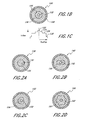
- FIG. 1A illustrates a perspective view of a double-clad fiber (DCF);
- Figure 1B illustrates a cross-sectional view of the double-clad fiber of Figure 1A taken along the lines 1B-1B in Figure 1A, in which the double-clad fiber has a basic configuration comprising a generally circular core surrounded by a generally circular first (inner) cladding, which is surrounded by a generally circular second (outer) cladding;
- Figure 1C illustrates the refractive index profile of the basic configuration of the double-clad fiber of Figures 1A and 1B;
- Figure 2A illustrates an embodiment of a double-clad fiber having an offset core within the first (inner) cladding
- Figure 2B illustrates an embodiment of a double-clad fiber having a core surrounded by a rectangular first (inner) cladding
- Figure 2C illustrates an embodiment of a double-clad fiber having a core surrounded by a D-shaped first (inner) cladding
- Figure 2D illustrates an embodiment of a double-clad fiber having a core surrounded by a scalloped first (inner) cladding
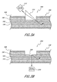
- Figure 3A illustrates a side-coupling method that uses a prism to inject pump light into the first (inner) cladding of a double-clad fiber
- Figure 3B illustrates an alternative side-coupling method that uses a V groove to inject pump light into the first (inner) cladding of a double-clad fiber
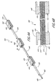
- Figure 4A schematically illustrates a perspective view of an embodiment of a laser system in accordance with the present invention, which includes a pump source that provides pump light to an end of a double-clad fiber and which includes a plurality of long-period fiber gratings positioned on the fiber;
- Figure 4B illustrates a cross section of the double-clad fiber of Figure 4A taken along the lines 4B-4B of Figure 4A;
- Figure 5 illustrates results from a simulation of the amount of pump power absorbed by the fiber core along the length of a double-clad fiber with a doped core and with LPFGs equally spaced along the length of the double-clad fiber;
- Figure 6 illustrates a schematic of an alternative embodiment of a double-clad fiber for use in a laser system in which the long-period fiber gratings are unevenly spaced along the length of the fiber;
- Figure 7 illustrates a schematic of an alternative embodiment of a double-clad fiber for use in a laser system in which at least two long-period fiber gratings are included at each grating node of the fiber;
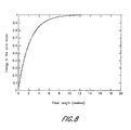
- Figure 8 illustrates results from a simulation of the amount of pump power absorbed by the fiber core along the length of a double-clad fiber with a doped core and with LPFGs equally spaced along the length of the double-clad fiber, wherein the core is a multimode core, and wherein the LPFGs couple each of 7 different cladding modes to each of 7 core modes;
- Figure 9 schematically illustrates a further embodiment of a double-clad fiber with a plurality of long-period fiber gratings mounted thereon;
- Figure 11 schematically illustrates a further embodiment of a double-clad fiber with a plurality of long-period fiber gratings mounted thereon wherein the fiber is bidirectionally pumped from two pump sources;
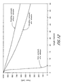
- Figure 12 graphically illustrates the results of simulations of the pump power remaining in an Er-doped double-clad fiber as a function of fiber length
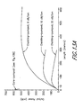
- Figure 13A graphically illustrates the output power of a 1530-nanometer Er-doped fiber laser as a function of the length of double-clad fiber for a core-pumped configuration and for three cladding-pumped configurations having different cladding loss characteristics;
- Figure 13B illustrates the output power of the core pumped configuration plotted in Figure 13A but on an expanded horizontal scale to show more detail;
- Figure 14 graphically illustrates the gains of three double-clad fiber amplifiers having different combinations of pump injection with some of the amplifiers including reflectors for recycling the pump light through the fiber;
- Figure 15A illustrates plots of the effective index of the modes in the mode groups versus the mode group number m for a first double-clad fiber with a core that has a step-index profile and that has an inner cladding with a step-index profile (diamond-shaped symbols);
- Figure 15B illustrates plots of the effective index of the modes in the mode groups versus the mode group number m for a second double-clad fiber that has a core having a step-index profile and that has an inner cladding having a parabolic-index profile (square-shaped symbols);
- Figure 15C illustrates plots of the effective index of the modes in the mode groups versus the mode group number m for a third double-clad fiber that has a core having a triangular-index profile and that has an inner cladding having a parabolic-index profile (triangle-shaped symbols);
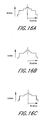
- Figure 16A illustrates the index profile for a double-clad fiber having a core and an inner cladding with respective step index profiles
- Figure 16B illustrates the index profile for a double-clad fiber having an inner cladding with a parabolic index profile and having a core with a step index profile
- Figure 16C illustrates the index profile of a double-clad fiber having an inner cladding with a parabolic index profile and having a core with a triangular index profile
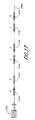
- Figure 17 schematically illustrates a system that comprises a double-clad fiber onto which are positioned at least a first long-period fiber grating having a first period for coupling cladding mode into a core mode and a second long-period fiber grating having a second period selected to equalize the power between cladding-mode groups.
- the double-clad fiber 100 comprises a single-mode core 102 having a generally circular cross section or other shapes, such as, for example, elliptical to produce a polarization-maintaining fiber.
- the core 102 is surrounded by a first (or inner) cladding 104, which also has a generally circular cross section.
- the core 102 is substantially centered within the inner cladding 104.
- the inner cladding 104 is surrounded by a second (or outer) cladding 106, which also has a generally circular cross section.
- the inner cladding 104 is centered within the outer cladding 106.
- the outer cladding 106 is surrounded by one or more protective coatings (e.g., a protective jacket) 108.
- the core 102 has a first refractive index 122.
- the inner cladding 104 has a second refractive index 124, which is lower than the first refractive index 122.
- the outer cladding 106 has a third refractive index 126, which is lower than the second refractive index 124.
- the protective coating 108 has a fourth refractive index 128, which is lower or higher than the third refractive index 126.
- the core 102 forms a first waveguide within the inner cladding 104, and the inner cladding 104 forms a second, highly multimoded waveguide within the outer cladding 106.
- the core 102 of the fiber 100 is doped with a rare-earth ion.
- the composition of the core glass is preferably selected to accept a high concentration of the dopant. If the dopant concentration is too low, the fiber length required to absorb a sizable fraction of the pump power will be hundreds of meters, which means a prohibitively high scattering loss and threshold for the fiber laser or amplifier.
- a core glass composition that tolerates higher quenching-free rare-earth concentrations, and by properly designing the cladding-to-core area ratio, most of the pump power can be absorbed in a few to tens of meters of fiber.
- a germano-alumino-silicate glass with a concentration of 0.5 wt.% Yb 2 O 3 is advantageously used in one embodiment in accordance with the present invention.
- Many other combinations of glass compositions, rare-earth dopants and concentrations of dopants can also be advantageously used.
- NA numerical aperture
- the numerical aperture (NA) of the inner cladding 104 should be as high as possible in order to capture as much of the pump power as possible.
- the NA is limited to approximately 0.4.
- Higher numerical apertures (NAs) can be achieved if the outer cladding is made of a low-refractive-index polymer, such as, for example, a Teflon-based polymer having a refractive index around 1.3. NAs as high as 0.6 have thus been achieved, as described, for example, in D.J. DiGiovanni et al., High-power fiber lasers (cited above).
- Figure 2A illustrates a double-clad fiber 130 wherein the core 132 is offset within the inner cladding 134.
- Figure 2B illustrates a double-clad fiber 140 wherein the core 142 is surrounded by an approximately rectangular inner cladding 144.
- Figure 2C illustrates a double-clad fiber 150 having a core 152 surrounded by a D-shaped inner cladding 154.
- Figure 2D illustrates a double-clad fiber 160 having a core 162 surrounded by a scalloped inner cladding 164.
- Each of the embodiments of Figures 2A, 2B, 2C and 2D advantageously reduce the incidence of helical rays, as discussed, for example, in A. Liu et al., The absorption characteristics of circular, offset, and rectangular double-clad fibers (cited above).
- pump light is preferably not coupled into the fiber by coupling the light into the core. Rather, the pump light is coupled into the inner cladding (e.g., the inner cladding 104 of the double-clad fiber 100 of Figures 1A and 1B) by end coupling so that the pump light is distributed over a large number of modes within the inner cladding 104. Some of these modes have spatial distributions that extend into the core. Accordingly, as these modes travel down the inner cladding 104, the pump light they carry overlaps spatially with the doped core 102 and is absorbed by the dopant.
- the inner cladding e.g., the inner cladding 104 of the double-clad fiber 100 of Figures 1A and 1B
- the pump light is advantageously coupled into the inner cladding 104 of the fiber 100 by one of the methods illustrated in Figures 3A and 3B.
- pump light from a large-area laser diode 310 is injected into the inner cladding 104 of the fiber 100 via a prism 312 placed on the inner cladding 104 of the fiber 100 in a location where the protective jacket 108 and the outer cladding 106 are removed.
- the prism 312 can be advantageously placed on the inner cladding 104 in accordance with a technique described, for example, in Th. Weber et al., A longitudinal and side-pumped single transverse mode double-clad fiber laser with a special silicone coating (cited above) and in Th. Weber et al., Side-pumped fiber laser (cited above).
- pump light from the large-area laser diode 310 is injected into the inner cladding 104 of the fiber 100 by using a V groove coupler 330 formed on the inner cladding 104 of fiber 100 in a location where the protective jacket 108 and the outer cladding 106 are removed.
- the V groove coupler 330 can advantageously be formed on the inner cladding 104 of the fiber 100 in accordance with a technique described, for example, in L. Goldberg et al., V-groove side-pumped 1.5 ⁇ m fibre amplifier (cited above).
- Pump light is focused onto a polished face of the V groove coupler 330 and is reflected by total internal reflection into the inner cladding 104.
- V-groove coupling leaves the fiber ends free and available, for example, for splicing.
- V-groove coupling and prism coupling also enable pump injection at multiple points along the fiber 100. These methods may produce highly efficient coupling of pump light into the inner cladding 104.
- the V-groove coupler 330 is used, for example, as much as 76% of the output power of the laser diode 310 can be coupled into a pump cladding. See, for example, L. Goldberg et al., V-groove side-pumped 1.5 ⁇ m fibre amplifier, cited above.
- the coupling efficiency between the light source and the optical fiber depends in part on the characteristics of the light source and those of the fiber.
- the area of the inner cladding 104 is typically tens to hundreds times larger than the area of the core 102.
- NA numerical aperture
- the large-area laser diode 310 may be implemented as a laser diode array. Unlike a single-mode laser diode, the large-area laser diode 310 is able to emit a very high output power (e.g., in excess of 100 watts).
- the large-area laser diode 310 exhibits a low brightness and cannot be coupled efficiently directly into the single-mode core 102.
- a double-clad laser system in accordance with a configuration described herein transforms a substantial fraction of the pump power launched into the inner cladding 104 into a highly spatially coherent output, with a brightness that can be thousands of times higher than that of the pump source.
- the double-clad fiber laser therefore acts as a brightness converter because it efficiently converts the low-brightness, multimode light of a high-power laser diode into high-brightness, single-mode laser radiation.
- One aspect of embodiments in accordance with the invention described herein is a method of using long-period fiber gratings placed along a double-clad fiber with a core doped with a laser ion (such as Er 3+ , Nd 3+ , Tm 3+ , or Yb 3+ for instance) to couple one or more pump cladding modes to a pump core mode.
- Pump radiation can be coupled into the cladding to excite cladding modes in the double-clad fiber.
- the long-period fiber grating causes optical power in the cladding modes to be transferred into one or more of the modes supported by the core. In this manner, light can be more efficiently introduced into the core.
- FIGS 4A and 4B illustrate a laser system 400 in accordance with a first embodiment.
- a double-clad fiber (DCF) 410 has a core 412, an inner cladding 414, an outer cladding 416 and a protective coating or jacket 418, as discussed above.
- Pump light from a pump source (e.g., a large-area laser diode) 420 is coupled into the inner cladding 414 of the DCF 410 using, for example, end coupling.
- a lens 422 between the pump source 420 and the DCF 410 assists in coupling.
- the pump power is distributed in some fashion among the groups of linearly polarized (LP) modes supported by the inner cladding 414.
- the pump power may be distributed approximately evenly between the groups of modes, as described, for example, in D. Gloge, Optical power flow in multimode fibers, Bell System Technical Journal, Vol. 51, No. 8, October 1972, pages 1767-1783.
- the pump power distribution does not need to be even for the embodiments the present invention and may preferentially fill one or more core modes.
- the groups of modes are numbered with an index m , where m varies between a minimum value of 2 and some maximum value M .
- the maximum value depends on the dimension and numerical aperture of the inner cladding 414.
- all of the modes in one group of modes have substantially the same propagation constant for certain geometries.
- All of the pump power is initially coupled into the inner cladding 414 and core and is distributed in some fashion among the M-2 groups of modes. Due to small random variations in the size, shape, and in general the index profile of the inner cladding 414, both along the length of the fiber 410 and along the perimeter of the inner cladding 414, these groups of modes are coupled to each other in such a way that after propagating a sufficient distance in the fiber, the optical power is distributed throughout the different mode groups. In some embodiments in accordance with the present invention, all groups of modes carry substantially the same power after propagation through a first unaltered portion 430 of the DCF 410 having a length L .
- the selected distance (or length) L depends on the magnitude and frequency spectrum of the spatial perturbations. For fibers fabricated by standard methods, it is possible to have a distance L in a range of 4-5 centimeters.
- a first long-period fiber grating (LPFG) 432 is placed on a portion 434 of the DCF 410.
- the first LPFG 432 can be written in the portion 434 by standard ultraviolet (UV) methods by using a photosensitive fiber for the DCF 410.
- the first LPFG 432 can be formed by clamping a mechanically ruled or chemically etched grating onto the portion 434 of the DCF 410, as described, for example, in U.S. Patent No. 6,282,341 for Tunable, Mechanically Induced Long-Period Fiber Grating with Enhanced Polarizing Techniques.
- Other techniques for placing the first LPFG 432 on the DCF 410 can also be used.
- the DCF 410 is selected such that its core 412 supports only a single mode (e.g., the LP 01 core mode). All modes other than the LP 01 core mode have most of their respective optical energies in the cladding and are referred to as cladding modes.
- the LPFG 432 is employed to couple light in the LP 02 cladding mode into the LP 01 core mode.
- the grating 432 provides phase matching to accommodate the different propagation constants of the LP 02 cladding mode and the LP 01 core mode.
- optical power within other modes in the set may flow into the LP 02 mode.
- the LPFG preferably couples this energy as well into the LP 01 core mode.
- the coupling length and the overall length of the first LPFG 432 in various embodiments are designed in accordance with well-known principles such that substantially all of the power in the LP 02 mode and any power in the LP 21 transferred to the LP 02 mode is coupled to the LP 01 core mode of the DCF 410, as discussed more fully below.
- a fraction of the power traveling in the inner cladding 414 has been coupled into the core 412.
- this fraction corresponds to 1/(M-2) of the pump power in the cladding.
- the power then propagates the distance L through a second unaltered portion 440 of the DCF 410 (e.g., a portion of the DCF 410 where no LPFG is formed).
- a second unaltered portion 440 of the DCF 410 e.g., a portion of the DCF 410 where no LPFG is formed.
- the power present in the core 412 is partially or fully absorbed by the dopant present in the core 412, thus creating a population inversion in the laser ion.
- power is also coupled among cladding modes and redistributed among the mode groups.
- a second LPFG 442 is placed on a portion 444 of the DCF 410 following the second unaltered portion 440.
- the second LPFG 442 is followed by a third unaltered portion 450 of the DCF 410 on which no LPFG is formed.
- the power propagates the distance L through the third unaltered portion 450 and then enters a portion 454 onto which a third LPFG 452 is formed.
- the structure of an unaltered portion of the DCF 410 followed by a portion having an LPFG formed thereon is iterated such that a chain of LPFGs is placed along the DCF 410 at regular intervals for the desired total length of DCF 410 to be excited.
- the total length can be determined by the particular device being considered.
- the total length can also be determined by a different criterion. For example, no further LPFGs are useful when, at a point on the DCF 410, the power remaining in the inner cladding 414 is insufficient to create a useful inversion.
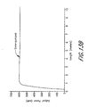
- Figure 5 illustrates the results of a computer simulation of the foregoing structure and process.
- the horizontal axis represents the position along the DCF 410 in meters, and the vertical axis represents the relative pump power absorbed by the dopant at each position.
- the simulation is based on a mathematical description of the coupling process.
- the fiber core 412 is assumed to be doped with a dopant that exhibits an absorption length of 10 centimeters at the pump wavelength.
- Each LPFG is selected to be 2.5 centimeters long.
- the distance L between each LPFG is substantially constant and is selected to be 10 centimeters.
- the DCF 410 has a core diameter of 5 microns, has a core numerical aperture (NA) of 0.17, has an inner cladding diameter of 100 microns, and has an inner cladding NA of 0.24.
- NA core numerical aperture
- the pump power is gradually coupled into the core. After a length of 10 meters, more than 40% of the pump power has been coupled from the cladding into the core and absorbed by the core dopant. After a length of about 23 meters, about 75% of the pump power has been absorbed by the dopant.
- the length of the DCF required to absorb the same percentage (i.e., 75%) of the pump power launched into the cladding would be approximately 55 meters.
- the reduction in length provided by the LPFGs in accordance with this aspect of the invention is a factor of about 2.4.
- LPFG can be fabricated along the entire length of the DCF.
- LPFGs of various lengths can be positioned at various places along the DCF. Fiber gratings many meters long can now readily be fabricated in the fiber manufacturing industry, making such alternative embodiments practical to implement.
- an LPFG can have a constant coupling strength along the entire grating length.
- an LPFG can have a coupling strength that varies along the length of the DCF in a predetermined fashion to accomplish a desired distribution of population inversion along the DCF.
- the same phenomenon also affects the first embodiment having a discrete distribution of LPFGs.
- the LPFGs closer to the pump source may be configured to have a lower coupling strength to compensate for the higher pump power.
- LPFG having an overall length greater than one coupling length
- pump power is coupled back and forth between the core and the cladding. That is, the pump power is transferred into and out of the core, but each time the pump power travels through the core some of the pump field is absorbed by the core dopant.
- increasing the length of each section of the LPFG does not optimally reduce the overall DCF length, increasing the length of each section can have other benefits. For example, fewer LPFGs may be easier to manufacture, may be simpler, may be less expensive and may provide other improvements in technical performance.
- Figure 6 illustrates a further alternative embodiment of a DCF 600 for use in a laser or amplifier system.
- a plurality of LPFGs 610 are formed on the DCF 600.
- the LPFGs 610 are discrete as discussed above; however, the LPFGs 610 are not equally spaced along the DCF 600. Rather, the spacings between the LPFGs 610 are varied to form a pattern to create a desired distribution of population inversion along the fiber or to produce any other effect that affects the performance of the fiber device, laser, amplifier, broadband source, or other optical device into which the DCF 600 is incorporated.
- the distances can advantageously be selected to create a constant or a nearly constant population inversion along the DCF.
- FIG 7 illustrates another alternative embodiment of a DCF 700 in which a plurality of LPFG nodes 710 are located along the DCF 700 at discrete locations.
- each LPFG node 710 comprises at least a first LPFG 712 and a second LPFG 714.
- the first and second LPFGs 712, 714 can be placed next to each other along the fiber 700, as illustrated in Figure 7.
- the first and second LPFGs can be side-by-side or combined in a single grating.
- the first and second LPFGs may be superimposed over the same length of fiber using, for example, UV techniques for writing gratings in the core.
- Each LPFG 712, 714 is designed to couple one specific group of modes m to the LP 01 core mode at the respective LPFG node 710. This approach advantageously results in coupling more power from the cladding to the LP 01 core mode at each LPFG node 710 so that the required overall length of the DCF 700 is shortened.
- the core of the DCF carries several modes instead of carrying a single mode.
- this type of fiber is advantageous in fiber lasers that deliver either a large peak power or a large continuous-wave power.
- the intensity of the power circulating in the fiber core is approximately the power in the core divided by the core area. When the intensity is too high, the power generates undesirable optical nonlinear effects that are detrimental to the operation of the laser, such as stimulated Brillouin scattering, which limits the maximum output power that can be generated.
- the high circulating intensity can also induce undesirable thermal effects in the core region. The high circulating intensity can also cause catastrophic breakdown of the fiber end faces. The thermal effects can also limit the maximum achievable output power.
- This type of fiber e.g., a fiber having a multimode core
- this type of fiber can be pumped with a different arrangement, in which each LPFG is designed to couple a particular cladding mode to one of the core modes.
- FIG. 8 The results of a simulation of an embodiment in accordance with this aspect of the invention are illustrated in Figure 8 for a DCF with a core diameter of 20 microns and an inner cladding diameter of 40 microns.
- the core of the simulated DCF carries 17 modes.
- Each LPFG in the chain is configured to couple 7 cladding modes to 7 of the core modes.
- These LPFGs may comprise grating of different period superimposed (e.g., by UV fabrication techniques) or arranged sequentially along the DCF. These different gratings couple individual cladding modes into separate core modes.
- the LP 05 cladding mode couples to the LP 01 core mode; the LP 14 cladding mode couples to the LP 11 core mode; the LP 24 cladding mode couples to the LP 21 core mode; the LP 33 cladding mode couples to the LP 31 core mode; the LP 43 cladding mode couples to the LP 41 core mode; the LP 52 cladding mode couples to the LP 51 core mode; and the LP 62 cladding mode couples to the LP 61 core mode.
- the set of cladding modes (and thus the set of core modes) was selected because the modes in the sets belong to different groups of modes.
- mode scrambling e.g., power diffusion among the cladding modes
- Mode scrambling may be implemented as described, for example, in D. Gloge, Optical power flow in multimode fibers (cited above).
- the mode scrambling effect requires a fiber having the right level and spectrum of core diameter or other spatial perturbations.
- Such fibers are readily available, as described, for example, in M.E. Fermann, Single-mode excitation of multimode fibers with ultrashort pulses, Optics Letters, Vol. 23, No. 1, January 1998, pages 52-54.
- the core can also be advantageously doped with other laser ions.
- the embodiments in accordance with the present invention can be implemented with types of optical waveguides other than fibers.
- Embodiments in accordance with aspects of the present invention have many benefits. For example, the length of DCF needed to inject and absorb the pump cladding power into the core of the fiber can be reduced, which reduces the length of the whole fiber laser. Reducing the length of the fiber reduces the cost of the device and also makes it easier to produce stable single-longitudinal fiber lasers.
- This deleterious effect is generally combated by increasing the threshold power of SBS, by increasing the fiber core size, by increasing the rare-earth concentration in the core, and/or by pumping at wavelengths that absorb more strongly.
- Increasing the rare-earth concentration in the core and pumping at wavelengths that absorb more strongly enable the DCF length to be reduced, and thus the SBS threshold power to be increased.
- the core size cannot be made indefinitely large, and in many applications causing the laser to oscillate on the fundamental mode becomes increasingly difficult.
- the rare-earth concentration in a glass core can be increased only so high before the onset of other deleterious effects, such as ion quenching, which destroys the efficacy of the ions as a laser material.
- the DCF length can be further reduced without increasing the rare-earth concentration, thus producing fiber lasers with a higher output power.
- a two-fold length reduction will enable increasing the output power of the laser by a factor of two before the onset of stimulated Brillouin scattering (SBS).
- SBS stimulated Brillouin scattering
- the same general benefits also apply to high-power fiber amplifiers.
- One limiting factor is the absorption length of the dopant, which depends on the dopant.
- the proper placement of the long-period fiber gratings at specific locations along the fiber couples power from the one or more pump cladding modes into a doped core according to a predetermined pattern to cause the distribution of the dopant population inversion along the core to take a desired form.
- the noise figure in an amplifier can be reduced by making the inversion profile more uniform, since areas of the core that see a low inversion (as may occur at the far end of a doped fiber pumped unidirectionally) suffer more strongly from the noise, and worsen the noise figure of the amplifier.
- the LPFGs may be positioned closer farther from the input end of the fiber.
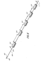
- FIG. 9 illustrates a further embodiment of a DCF 900 with a plurality of LPFGs 910 mounted thereon in accordance with aspects of the present invention.
- the DCF 900 may be incorporated into a laser or an amplifier.
- the DCF 900 has a core, an inner cladding, an outer cladding and a protective coating as described above.
- the DCF 900 receives pump light from a pump source 920.
- the pump light is preferably launched into the inner cladding, as described above.
- the pump light from pump source 920 can be end-coupled to the DCF 900, as shown in Figure 9, or the pump light can be coupled to the DCF 900 by other techniques, such as, for example, by using the prism illustrated in Figure 3A or by using the V groove illustrated in Figure 3B.
- each LPFG 910 is designated as a point A
- the output of each LPFG is designated as a point B.
- pump light is launched unidirectionally at a point to the left of point A (e.g., by end-coupling, prism coupling, V-groove coupling, or the like), and the pump light travels in the forward direction (left to right in Figure 9) such that the pump light travels in the direction from point A to point B with respect to each LPFG 910.
- the opposite direction is referred to herein as the backward direction.
- signal refers to an optical signal launched into the core of the DCF (either forward or backward) and amplified by the pumped DCF 900.
- signal refers to the laser signal circulating in the DCF laser resonator.
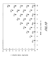
- the modes supported by the core and inner cladding are nearly linearly polarized LP lq modes.
- Any modes that have the same index m have, as an approximation, substantially the same propagation constant ⁇ m cl . See, for example, D. Gloge, Optical power flow in multimode fibers (cited above).
- the modes are therefore conveniently lumped in groups of index m , such that all modes within a group have substantially the same propagation constant.
- the group index m varies between 2 and a maximum value M that depends on the cladding dimensions and the NA.
- Figure 10 only shows the individual modes for values of m from 2 to 10 and values of l from 0 to 10.
- the lowest value of m is 2.
- the LP 01 mode can be viewed as both the lowest-order waveguide mode and the fundamental core mode.
- the DCF 900 is designed such that its core carries a single mode and all modes other than the LP 01 mode have most of their energy in the cladding (i.e., these other modes are cladding modes).
- the pattern continues for higher indices, m .
- the power is distributed substantially equally between mode groups; however, the power is not distributed equally between individual modes.
- the LP 11 mode, the only mode in the group m 3, also carries a power P g .
- a given cladding mode (of propagation constant ⁇ m cl ) is coupled to a given core mode (of propagation constant ⁇ n co ) when two conditions are met.
- the first condition is that propagation constant ⁇ n co and the propagation constant ⁇ m cl , which are both functions of wavelength, are phase-matched.
- the period ⁇ of the LPFG is appropriately selected.
- phase-matching and resultant coupling between the LP 08 mode and the LP 01 core mode occurs around a wavelength, ⁇ , of 1530 nanometers using a LPFG with a period, ⁇ , of 530 micrometers ( ⁇ m).
- the second condition requires that the two modes to have the same azimuthal symmetry (i.e., the two modes must have the same azimuthal mode number l) for the case where the LPFG grooves are perpendicular to the fiber axis.
- only LP 0q cladding modes e.g., LP 02 , LP 03 , LP 04 , etc.
- LP 01 core mode can be coupled to the core mode.
- other modes such as the LP 03 , LP 04 , LP 05 , etc. can be coupled to the LP 01 core mode.
- the specific core and cladding modes that are described herein as being coupled should not be construed as limiting.
- the two modes to have the same azimuthal symmetry does not apply if the grating is not perpendicular to the longitudinal axis of the fiber, such as is the case for a blazed grating.
- the LP 11 mode can be coupled for example to the LP 01 mode.
- the overlap of the electrical fields caused by the perturbation of the grating is zero if the modes do not have the same azimuthal symmetry.
- the coupling coefficient ⁇ is proportional to the spatial overlap integral between the electric fields of the two coupled modes. See, for example, T. Bach, Cladding-mode resonances in short- and long-period fiber grating filters (cited above). If the core and cladding modes have the same azimuthal symmetry, the integral is non-zero and coupling can take place. If the symmetries are different, the modes are orthogonal and the integral is exactly zero. Thus, ⁇ is zero, and no power can be coupled between the two modes, even if the two modes are phase matched.
- the coupling constant is proportional to the spatial overlap of both the fields and the refractive index perturbation and that if the grating is tilted with respect to the fiber axis (e.g., blazed), then the coupling is not necessarily zero if the spatial overlap of the modes is zero.
- a particular LPFG 910 of period ⁇ can only phase-match one group of modes to a particular core mode in accordance with Equation 2.
- the LP 02 mode can be matched to the LP 01 core mode and the LP 78 can be matched to the LP 73 core mode if the difference in propagation constant ( ⁇ ) between the LP 02 and LP 01 mode and the difference in propagation constant ( ⁇ ) between the LP 78 and LP 73 are substantially the same.
- Only one cladding mode can be matched to a given core mode with a given grating periodicity ⁇ . This is true for all index profiles.
- this power in the mode LP 0 q may change and more power may be coupled out of the mode group than P p / M / q .
- it may be advantageous to choose the lowest possible value of q (e.g. q 2), which is the LP 02 cladding mode.
- Coupling substantially all the LP 02 cladding mode power into the LP 01 core mode is accomplished by selecting the LPFG coupling length and coupling coefficient, as discussed below. Since all other LP 0q modes potentially carry less power, using an LPFG designed to couple one of these other modes to the LP 01 mode may couple less power into the core. As indicated above, however, some power may be transferred between modes within the same mode group, in which case, the power may be more efficiently transfer out of the mode group by the LPFG.
- the maximum power coupled by the first LPFG 910 into the LP 01 core mode is P p l2(M-1).
- the power remaining in the cladding is then P p -(P p / 2(M-1)).
- the second LPFG 910 couples 1/(2 (M-1) ) of this amount, or P p (1-1/(2 (M-1) ))/2 (M-1).
- the number of LPFGs 910 required to couple substantially all the pump power into the core is therefore roughly of the order of 2 (M - 1) assuming no transfer of optical power between modes within the mode group.
- M - 1 the number of LPFGs 910 required to couple substantially all the pump power into the core.
- the maximum power coupled, for example, by the first LPFG 910 into the LP 01 core mode is greater than P p / 2(M-1) and may be increased, e.g., to P p / (M-1). Accordingly, as a result of mode degeneracy, the power couple may be for example between about P p lk(M-1) and P p l(M-1) for a cladding mode group having k modes.
- the operation of the DCF 900 with the plurality of LPFGs 910 is as follows.
- the configurations of the LPFGs 910 are preferably selected to couple the LP 0q cladding modes to the LP 01 mode.
- pump light is present in both the LP 0q mode (largely due to diffusion) and the LP 01 mode (residual power unabsorbed by the dopant).
- the LPFG couples pump light not only from the LP 0q cladding mode to the LP 01 core mode, but also from the LP 01 core mode to the LP 0q cladding mode.
- the net direction of power flow at each LPFG i.e., whether more power is coupled from the cladding to the core (i.e., the desirable direction) or from the core to the cladding (i.e., the undesirable direction) depends on the relative power carried by the two modes at point A.
- the relative phase of the two modes at point A will influence the output phases of the fields.
- the relative phase depends strongly on a number of variables that cannot be easily controlled, such as the fiber temperature, temperature gradients, stresses, static and dynamic pressure, and the like. Therefore, the relative phase is a random variable between 0 and 2 ⁇ .
- One aspect of embodiments in accordance with the present invention is a method that reduces or minimizes this undesirable dependence of the coupled power on the relative phase of the modes. This goal is accomplished by satisfying two conditions.
- the method comprises selecting the spacing between the LPFGs 910 and selecting the pump absorption such that at point A of each LPFG 910 more pump power is in the cladding mode of interest than in the core mode, as discussed below.
- the second condition assures that the power remaining in the core at point A (P core ) is fully coupled into the cladding at point B, and also assures that the power in the cladding mode of interest at point A (P clad ) is fully coupled into the core at point B. If P clad is greater than P core in accordance with the first condition, more power is coupled into the core than is coupled out of the core. Thus, each LPFG 910 increases the net power in the core at point B by an amount equal to P clad -P core .
- the optimum spacing between the LPFGs 910 depends on several design parameters, such as, for example, the rate of diffusion between cladding modes (discussed below) and the type of laser transition involved in the dopant.
- the unabsorbed pump power remaining in the core at point A should be smaller than the pump power in the cladding mode of interest at point A.
- the unabsorbed pump power remaining in the core depends on how much power is in the core at point B of the previous LPFG and depends on the rate of pump absorption in the core.
- the rate of pump absorption in the core depends on the dopant, the dopant concentration, the pump wavelength, and the pump intensity in the core, in addition to other parameters.
- the unabsorbed pump power remaining in the core also depends on the length of fiber L s between adjacent LPFGs 910 and on the amount of power diffused into the core mode along the length of fiber separating two adjacent LPFGs 910.
- the pump power in the cladding mode of interest depends on how much pump power is in the cladding at point B of the previous LPFG, depends on the rate of diffusion between cladding modes (discussed below), and depends on L s .
- a longer L s results in less power remaining in the core unless mode diffusion replenishes the core mode faster than the core mode is absorbed by the dopant.
- a longer L s thus results in more power in the cladding mode of interest.
- the optimum value for L s can be either calculated or measured experimentally.
- the low pump power means that the laser ions are poorly inverted. This is acceptable for a laser ion that does not exhibit ground-state absorption (GSA), such as a four-level transition laser ion, since ions in the ground state do not induce absorption loss on the signal.
- GSA ground-state absorption
- This method can advantageously be used, for example, with the 1.06-micron transition of Nd 3+ .
- ions in the ground state absorb the signal and therefore introduce an undesirable signal loss.
- a sufficiently high population inversion should be maintained in that region to assure that a signal traveling through this region experiences close to zero GSA, or even better, experiences some gain. This goal can be advantageously accomplished in three ways.
- One method of maintaining a sufficient population inversion is to select the spacing between adjacent LPFGs 910 such that sufficient pump power remains in the core in that region to create the necessary population inversion.
- the spacing is advantageously selected by using standard laser rate equations or by using commercially available optical fiber amplifier simulators (e.g., simulators for Er 3+ ) to calculate the gain per unit length at every point along the DCF 900.
- the LPFG spacing is adjusted until the gain is positive everywhere. If all positive gain cannot be achieved, the LPFG spacing is adjusted for minimal negative gains (e.g., minimal attenuations).
- a second method for maintaining a sufficiently high population inversion is to select an input pump power high enough that sufficient pump power remains to the left of point A to create the population inversion required to minimize or even cancel signal GSA loss.
- a third method is illustrated by a DCF 1100 in Figure 11 having a plurality of LPFGs 1110.
- the DCF 1100 is pumped bidirectionally from a first pump source 1120 and from a second pump source 1130. Since each LPFG 1110 operates simultaneously in both directions, each LPFG 1110 also couples the backward pump power propagating from point B toward point A into the core. As a result of the backward pump power traveling from right to left at point A, pump power will be present to the left of point A.
- Each of the three methods is used advantageously, for example, with the 4 I 13/2 ⁇ 4 I 15/2 transition of Er 3+ or for the 2 F 5/2 ⁇ F 7/2 transition of Yb 3+ .
- the mode diffusion length L d is the length of fiber required to replenish the depleted cladding mode of interest to 1-(1/e) (approximately 63%) of its steady-state power. After two diffusion lengths (2 L d ), the cladding mode power is replenished to 1-(1/e 2 ) (approximately 86%) of its steady-state value. Additional diffusion lengths replenish the cladding mode power further. Measured L d values as short as 10-20 cm have been reported. See, for example, D. Gloge, Optical power flow in multimode fibers (cited above).
- the LPFGs 910 can be separated by a few diffusion lengths (e.g., two to three or more diffusion lengths) for a DCF 900 having a core doped with a laser ion that exhibits no signal GSA.
- the LPFGs 910 are advantageously separated by a shorter distance (e.g., only one or two diffusion lengths).
- the DCF 1100 device can advantageously be bidirectionally pumped using two sources 1120, 1130, as illustrated in Figure 11.
- shorter spacing and bidirectional pumping can both be used.
- the optimum numerical value of the optimum spacing depends on a large number of system parameters and can be advantageously determined using known modeling techniques, by experimentation, or by a combination of modeling and experimentation.
- the mode diffusion length L d depends on the mode numbers, the pump wavelength, and the magnitude and spatial frequency spectrum of the fiber index profile perturbations. Since the pump mode and wavelength are generally set by other constraints (some of which were discussed above), the main parameters that are advantageously adjusted in practice to control the diffusion length are the magnitude and the frequency spectrum of the waveguide perturbations. Measured L d values from on the order of 4-5 centimeters or shorter to many meters have been reported. See, for example, D. Gloge, Optical power flow in multimode fibers (cited above), and M.E. Fermann, Single-mode excitation of multimode fibers with ultrashort pulses (cited above). The wide range in the values of L d is a direct consequence of variations in the magnitude and the frequency of the fiber index profile perturbations. In certain embodiments in accordance with aspects of the present invention, the mode diffusion length L d is adjusted to a desired value by selection of parameters of the double-clad fiber.
- One benefit of embodiments in accordance with aspects of the present invention is the minimization of the length of a cladding-pumped DCF device.
- the required DCF length depends on the fiber absorption length, the mode diffusion length, and the grating length.
- the spacing between LPFGs is also a significant length parameter; however, the spacing is preferably scaled in accordance with the mode diffusion length L d . Thus, the spacing is not an independent parameter.
- Most laser dopants have a relatively small absorption at the pump wavelength for pump light guided in the core (of the order of 30 dB per meter or less for a low pump power and much less for a practical, high pump power).
- the absorption is even weaker (e.g., by a factor in the range of 5-50, depending on the pump power level and depending on the ratio R between the core area and the cladding area, as discussed below).
- the minimum DCF length is thus set mostly by the rate of pump absorption.
- the rate of pump absorption is characterized by the pump absorption length, which is the length required to absorb 1-(1/e) of the pump power.
- the pump absorption length is limited by the maximum laser ion concentration that can be achieved in the core.
- the absorption length at high pump power is typically one to a few meters, so that the fiber needs to be in the range of a few meters to a few tens of meters.
- the next strongest parameter is the mode diffusion length, which can be as short as 10-20 centimeters.
- the next shortest and also the last of the length characteristics is the coupling length of a typical LPFG, i.e., the length required to achieve 100% coupling, which is typically on the order of 2 centimeters.
- a shorter diffusion length allows the LPFGs to be more closely spaced so that a shorter device (e.g., a shorter DCF length) can be produced.
- a minimum DCF length of a few high-power absorption lengths would be obtained if all of the pump power could be launched into the core of the DCF; however, as discussed above, the low spatial coherence and low brightness of large area high-power multimode laser diode pump sources generally precludes launching efficiently into the core. Accordingly, in embodiments in accordance with aspects of the present invention, the DCF is cladding-pumped.
- the length of the DCF needed to absorb most of the launched pump power depends on the spatial overlap between the pump light and the doped core, which depends on the ratio of the inner cladding area to the core area.
- the length of the DCF would be many times longer in the absence of the LPFGs described herein, which couple pump light from the cladding to the core and thereby increase the rate of pump absorption.
- Figure 12 presents the results of simulations of the pump power at 980 nanometers remaining in an Er-doped DCF as a function of fiber length.
- the inner cladding area is 400 times larger than the core area and the input power is 1 watt.
- the absorption of the fiber is 7.7 dB per meter for the core mode. Pump saturation effects are taken into account in the simulations.
- Figure 12 shows that in the core-coupled DCF, the same pump absorption of 62% is achieved after a length of only about 3 meters, or about one-seventeenth the length required when the power is coupled to the cladding. This absorption is used for comparison when describing the benefits of embodiments of the present invention.
- the graphs in Figure 12 provide a numerical example for the improvement that can be advantageously achieved by embodiments in accordance with aspects of the present invention.
- a cladding-pumped DCF used with a series of LPFGs behaves asymptotically like the same DCF pumped in the core.
- the foregoing examples are presented herein as illustrations rather than as best possible scenarios in order to show that embodiments in accordance with aspects of the present invention allow the DCF length to be reduced.
- the fiber length may be reduced by a factor of about 17 or more.
- a preferred embodiment advantageously comprises a series of many (e.g., 10-100) LPFGs that couple 100% of the power.
- the LPFGs are placed next to each other along the DCF.
- the effects of the LPFGs combine to couple most of the pump power into the core.
- the combined length of the LPFGs is 10-100 times the length of a typical LPFG length. For example, for LPFGs having individual lengths of approximately 2 centimeters, the combined length of 100 LPFGs is approximately 2 meters.
- all the pump power is coupled into the core mode over a DCF length of approximately 2 meters or less.
- This DCF length may or may not be sufficient for the pump power to be absorbed by the core dopants. Therefore, the portion of the DCF downstream from the series of LPFGs, which behaves like a core-pumped fiber, is advantageously constructed to be long enough to absorb the required fraction of remaining pump power. In other words, the total DCF length, including the portions of fiber under the LPFGs, must be a few high-power absorption lengths long. This configuration therefore requires nominally the same length of DCF as the same DCF pumped in the core.
- an ideal short-length design for a core-pumped DCF can be asymptotically reached by embodiments in accordance with the above-described aspects of the present invention by selecting a DCF with a very short diffusion length (e.g., by selecting a diffusion length L d much shorter than the grating length (L d ⁇ L g ), which is less than approximately 2 centimeters).
- this configuration can be implemented with fewer gratings of longer length that effectively combine smaller gratings together into one or more larger gratings.
- Output power can be increased along with the reduction in fiber length by using LPFGs, as illustrated in Figure 13A and Figure 13B.
- Figures 13A and 13B show the output power of a 1530-nanometer Er-doped fiber laser as a function of fiber length.
- the fiber laser is made with the same DCF as described above in connection with Figure 12.
- the DCF is pumped with 1 watt of pump power at a wavelength of 980 nanometers.
- the fiber loss for a core mode (signal and pump) is 30 dB per kilometer.
- the fiber laser output power is maximum for a length of about 1.3 meters, and the maximum output power is about 600 milliwatts.
- the pump power is launched in the cladding, a considerably longer fiber is required for the fiber laser to reach its maximum output power, and this maximum output power is lower.
- this maximum output power is about 500 milliwatts, and the maximum output power occurs with about 450 meters of DCF.
- the maximum performance of a cladding pumped DCF is nominally the same as if the DCF was core pumped.
- the embodiments in accordance with aspects of the present invention that advantageously employ one or more LPFG may reduce the fiber laser length from around 200 meters to about 1.3 meters (e.g., by a factor of about 150) and increase the fiber laser output power by anywhere from 20% to 300% or more, depending on the cladding mode loss.
- Other performance specification of the systems described herein may be larger or smaller depending on the particular configuration.
- FIG 14. Another example of the improvements achieved by embodiments in accordance with aspects of the present invention is illustrated in Figure 14.
- the gains of three DCF amplifiers are plotted. Each amplifier is made with the same fiber.
- a first amplifier which has the gain characteristics plotted by the upper graph 1410
- the core of the fiber is pumped, and a pump reflector is placed at the far end of the fiber.
- a second amplifier which has the gain characteristics plotted by the middle graph 1420
- the cladding of the fiber is pumped and a reflector is provided at the far end of the fiber.
- the cladding of the fiber is pumped and no reflector is provided.
- the best performance is that of the core-pumped amplifier.
- the performance of the cladding pumped amplifier can be made to more closely resemble the performance of the core-pumped amplifier.
- the gain improvement enabled may be about 11 dB, while the DCF length is reduced from 32 meters to 2 meters, a factor of 16.
- each mode group has a different propagation constant ⁇ m cl , which is proportional to the effective refractive index for the mode group.
- Figures 15A-15C plot the effective index of the modes in all the mode groups versus the mode group number m for three fiber configurations shown in Figures 16A-16C.
- the plots with diamond symbols in Figure 15A represent the effective indices of a standard fiber that has a core with a step-index profile and that has an inner cladding with a step-index profile as shown in Figure 16A. Note that as the mode group number increases, the differences between the indices of the individual modes within each group become larger and the limits of the approximation referred to above are manifested for this fiber configuration.
- the plot with square symbols in Figure 15B represents the effective indices of a fiber that has a core with a step-index profile and that has an inner cladding that has a parabolic index profile as shown in Figure 16B.
- the plot with triangular symbols in Figure 15C represents the effective indices of a fiber having a core with a triangular-index profile and an inner cladding with a parabolic index profile as shown in Figure 16C.
- the core radius is 3 microns
- the core numerical aperture is 0.11
- the inner cladding radius is 35 microns
- the inner cladding numerical aperture is 0.24
- the outer cladding diameter is 125 microns.
- the propagation constant differences between adjacent mode groups for the standard step-index inner-cladding fiber are not constant. Instead, ⁇ increases as m increases. Consequently, an LPFG selected to have a period that phase-matches a given mode group m -2 to a mode group m will not have the correct period to couple other mode groups together.
- efficient mode diffusion along the DCF will require a DCF with a broad range of index profile perturbation periods, which generally requires a rather long diffusion length.
- phase-matching can be achieved over a broader range of mode groups.
- the DCF has an inner-cladding with a parabolic index profile so that the DCF mode diffusion length is much shorter than the mode diffusion length of other profiles (e.g., step-index).
- the first example does not use LPFGs.
- the shorter diffusion length causes mode mixing to occur over shorter distances. Hence, the rate of pump absorption by the dopant is increased, and a shorter DCF can be used.
- a second example does utilize LPFGs in combination with the parabolic index profile.
- the LPFGs increase the coupling of light from the cladding into the core.
- the minimum distance between adjacent LPFGs is substantially shortened because, as discussed above, the mode diffusion length is shortened.
- the spacing between adjacent LPFGs can be reduced, preferably to the limit imposed by pump absorption in the core wherein L abs determines the spacing between the LPFGs (i.e., L abs >L d ).
- an additional LPFG is used to efficiently couple all cladding modes together. This speeds up the mode diffusion and reduces the fiber length needed to equalize the power between cladding-mode groups.
- the period ⁇ ' is different from the period ⁇ of the LPFGs used to couple a particular cladding mode to the core mode, so that two distinct series of LPFGs are involved.
- the period ⁇ ' can be chosen to be equal to ⁇
- the average can be calculated over a few lower order mode groups, which may carry more power.
- a DCF 1700 optically coupled to a source 1720 has a first LPFG 1710 of period ⁇ .
- a second LPFG 1712 of period ⁇ ' is inserted on the DCF after each LP 0q ⁇ LP 01 LPFG 1710.
- the first LPFG (period ⁇ ) 1710 couples the power in the LP 0q cladding mode to the LP 01 core mode.
- the second LPFG (period ⁇ ') 1712 equalizes the power between cladding-mode groups (i.e., the second LPFG 1712 replenishes the LP 0q mode power).
- the laser ions in the core absorb the power in the LP 01 core mode. This sequence is repeated a number of times, until the desired fraction of pump power is absorbed by the dopant.
- the configuration in the third example can be further simplified in a fourth example by selecting a fiber core in such a way that a single grating can perform the functions of these two individual LPFGs 1710, 1712.
- the fourth example advantageously reduces the insertion loss introduced by the LPFGs.
- the fourth example preferably is not implemented with a step-index core profile because, as seen in Figure 15A, ⁇ m cl - ⁇ m-1 cl ⁇ 2 cl - ⁇ 1 co , and thus the same period does not effectively couple the LP 02 cladding mode to the LP 01 core mode and also couple adjacent cladding modes groups together.
- the differences between the effective indices of adjacent mode groups are not exactly equal, but they are so close that all mode groups are strongly coupled with a single grating of fixed period.
- the maximum spread between the effective indices of all the mode groups is only about 3%.
- the fourth example thus comprises a series of identical LPFGs spaced by a length determined primarily by the absorption strength of the laser ions.
- Another advantage of a parabolic-profile inner cladding is that the number of modes supported by the inner cladding is lower, by a factor of 2, compared to a step-index profile inner cladding with the same diameter and peak index difference (approximately (V clad ) 2 /4 versus approximately ( V clad ) 2 /2 , where V clad is the V number of the inner cladding).
- the power per mode is multiplied by approximately two in a parabolic-profile inner-cladding DCF compared to a step-index inner-cladding DCF.
- the absolute pump power coupled per LPFG is also multiplied by the same factor. Hence, the number of LPFGs required to couple a given fraction of launched pump power is decreased by approximately a factor of two.
- parabolic-profile inner cladding Another advantage of a parabolic-profile inner cladding is that it increases the optical confinement of the cladding modes. As a result, for most of the cladding modes the electric field in the core is larger than for a step-index profile (i.e., the fractional modal power in the core is higher). This has two beneficial consequences. First, the absorption rate of a given cladding mode is higher.
- One embodiment in accordance with aspects of the present invention, which does not utilize LPFGs, is a DCF with a parabolic-profile inner cladding in which pump power is launched by standard means (e.g., by coupling into the end or the sides of the cladding).
- the rate of pump absorption is then substantially increased compared to that of a standard DCF with a step-index inner cladding with the same diameter and NA, and excited under the same conditions.
- a standard DCF with a step-index inner cladding with the same diameter and NA and excited under the same conditions.
- the calculated increase in absorption coefficient averaged over all the modes (cladding modes and core modes) is about a factor of 2.
- a second benefit of this stronger confinement is that the coupling coefficient ⁇ of an LPFG made in a fiber with a parabolic inner cladding profile is also increased compared to what it is in a DCF with a step-index inner cladding.
- the advantage can be understood by virtue of the definition of the LPFG coupling coefficient ⁇ given above in relations to Equation 3 and 4.
- the coupling coefficient is proportional to the spatial overlap of the electric fields of the two coupled modes, calculated over the region of the fiber cross-section where the LPFG periodic index perturbation is applied. In a mechanically induced LPFG, this perturbation spreads across the cross-section of the fiber. In a UV-induced LPFG, this perturbation is typically confined to the core.
- the degree of increase in the LPFG coupling coefficient depends on a number of parameters, such as, for example, the cladding mode number.
- the degree of increase is particularly significant for low-order modes.
- an exemplary fiber has a step-index core with a radius of 7.1 microns and an NA of 0.11, and has an inner cladding with a diameter of 32 microns and an NA of 0.19. Calculations based on the fiber having those parameters show that the LP 02 ⁇ LP 01 coupling coefficient ⁇ 0201 is about 12 times stronger when the inner cladding has a parabolic index profile than when the inner cladding has a step-index profile.
- the increased coupling coefficient has beneficial consequences in many applications of LPFGs in addition to the above-described devices made with double-clad fibers.
- employing a fiber having an inner cladding with a parabolic profile enables a shorter UV-induced LPFG to be uses.
- a shorter mechanically induced LPFG can be used.
- the same LPFG can be utilized with a lower index perturbation (with, e.g., lower coupling over the same length).
- a fiber having an inner cladding with a parabolic index profile produces stronger grating of the same length.
- the foregoing embodiment can be modified for use with a fiber (with or without double cladding) in which the inner cladding (or the only cladding) has a parabolic profile.
- the overall LPFG can be extremely short, about 12 times shorter than a comparable LPFG made in an identical fiber with a step-index cladding.
- the LPFG may comprise a comparable length but have a weaker index perturbation, which results in a much lower internal loss in the final LPFG.
- cladding with a parabolic index profile has been described, other profiles that provide increased confinement or an increased coupling coefficient may be employed.
- This cladding profile may be higher or peaked closer to the longitudinal axis through the fiber (e.g., at the core/cladding interface).
- the index in the cladding, such as the inner cladding preferably decreases outward in a radial direction.
- the core may have a peaked index profile other than parabolic that preferably increases confinement and/or the coupling coefficient.
- This core profile may be higher or peaked closer to the longitudinal axis through the fiber and may decease linearly or non-linearly outward in a radial direction.
- peaked or graded index profiles may be employed with a variety of fiber geometries such as those depicted in Figures 2A-2D.
- the LPFGs described herein can be advantageously fabricated on the DCF in a number of ways, such as, for example by applying a mechanical grating structure, by ultraviolet lithography, by melting, by stretching, by densifying, and other ways to change the local refractive index.
- Corrugated gratings may also be formed by etching away part of the fiber's cladding.
- Other methods of forming LPFGs, both those well known in the art as well as methods yet to be designed may be employed to produce the grating and the resultant optical effects.
- Index of refraction features that make-up the grating may be included in the cladding (i.e., inner cladding or the outer cladding) as well as the core.
- the index modulation in the core region is reduced by lowering the ultraviolet (UV) dosage.
- UV ultraviolet
- the lower index modulation results in a lower scattering in the UV-exposed region of the fiber core, and thus a lower propagation loss for the grating.
- Selecting the right compromise between grating strength and grating length leads to LPFGs and LPFG devices that are shorter and exhibit a lower loss.
- certain embodiments in accordance with particular aspects of the present invention include LPFGs having characteristics which couple more than one cladding mode to the core mode. Numerical simulations confirm that embodiments in having such LPFGs do increase the amount of pump power coupled into the core per unit length compared to embodiments that couple only one cladding mode to the core mode. However, modeling also shows that the amount of pump power coupled into the core mode depends on the relative phases of the cladding modes coupled to the core mode, as expected physically.
- an LPFG couples both the LP 0m and the LP 0n cladding modes to the core mode LP 01 .
- the LP 0m and the LP 0n cladding modes carry the respective powers P m and P n .
- the power coupled into the core mode at the output of the LPFG will be P m + P n (neglecting losses and dopant absorption along the LPFG).
- the power coupled into the core mode.
- the absolute phases of all the cladding modes depend strongly on a number of parameters.
- One parameter is the mode structure of the pump source or pump sources. The mode structure varies constantly over time due to thermal fluctuations in the source or sources.
- one cladding mode may be preferably coupled to one core mode.
- multimode DCFs are advantageous in certain applications where a large peak power or continuous-wave power travels in the fiber core. This is especially true of high-power fiber lasers.
- the signal intensity in the core (approximately the signal power divided by the core area) is too high, it induces undesirable nonlinear effects that are generally detrimental to the operation of the laser and thus limit the maximum output power that can be generated.
- the high laser intensity can also induce undesirable thermal effects in the core region, which also limit the maximum achievable output power.
- One effective method that has been used to reduce these intensity-dependent effects is to increase the core size, which reduces the intensity.
- a larger core supports multiple modes.
- embodiments in accordance with aspects of the present invention are advantageously utilized to couple a multiplicity of cladding modes to the core modes.
- the overall rate at which pump power is coupled into the core is increased and the device length is reduced.
- LPFGs are used not only to couple an LP 0q mode to the LP 01 core mode, but also to couple one or more cladding modes to a few or all of the higher order core modes.
- a first LPFG couples one of the LP 0q cladding modes (preferably the LP 02 mode) to the LP 01 core mode
- a second LPFG couples one of the LP 1q cladding modes (preferably the LP 12 mode) to the LP 11 core mode.
- This coupling is enabled because cladding modes with an azimuthal symmetry other than that of the LP 0m modes can effectively be coupled to a core mode with the same azimuthal symmetry.
- the two coupling processes are independent of the relative phase of the two cladding modes coupled to the core because each one is coupled to a different core mode.
- the net effect of this approach is that the pump power coupled to the core per unit length is increased.
- the power in the cladding modes is coupled into the core modes in accordance with the foregoing embodiment is 1/(kM)+1/((k+1)M)+..., where k is the mode group number of the lowest order cladding mode.
- the lower order cladding modes are core modes. Accordingly coupling the cladding modes to the core modes means that even larger order cladding modes are coupled to the lowest order core modes such as the LP 01 mode. Although this process may be less efficient for reasons described above, the coupling to a plurality of core mode may offset the inefficiency of coupling from higher order cladding modes.
- the coupling length of a particular higher order mode may be shorter than the coupling length of a lower order mode.
- a method to calculate the dependence of the coupling strength of an LPFG on the mode number can be found, for example, in T. Bach, Cladding-mode resonances in short- and long-period fiber grating filters (cited above).
- the coupling length of a higher order mode is shorter, the corresponding LPFG for coupling the higher order mode is shorter, and the DCF device length is reduced by using the corresponding LPFG.
- an LPFG comprises a superposition of two periods, one to couple the LP 02 cladding mode to the LP 01 core mode, and the other one to couple the LP 12 cladding mode to the LP 11 core mode.
- This LPFG has the same length as either an LP 02 ⁇ LP 01 LPFG or an LP 12 ⁇ LP 11 LPFG; however, the total coupled power is doubled.
- bidirectional pumping is incorporated by injecting pump power into the DCF from both directions or by placing a reflector at the far end of the DCF.
- pump power also travels from right to left at point A as shown in Figure 11, which causes pump power to remain to the left of point A.
- the remaining pump power allows the spacing between LPFGs to be increased, which minimizes the amount of forward pump power coupled out of the core by the LPFG, and which reduces the number of LPFGs required.
- This method is advantageous for dopants with three-level transitions, such as, for example, the 4 I 13/2 ⁇ 4 I 15/2 transition of Er 3+ .
- the reflector provides better utilization of the available pump power (by recycling unabsorbed pump power).
- coupling light from one or more cladding modes into one or more core modes by employing one or more LPFG may improve fiber lasers and amplifiers.
- Other methods of providing such coupling without LPFGs may also be utilized.
Landscapes
- Physics & Mathematics (AREA)
- Electromagnetism (AREA)
- Optics & Photonics (AREA)
- Engineering & Computer Science (AREA)
- Plasma & Fusion (AREA)
- General Physics & Mathematics (AREA)
- Lasers (AREA)
Claims (36)
- Doppelt ummantelte optische Faser (410; 600; 700; 1700), umfassend:einen Kern (412), der mit einer optisch aktiven Dotierungssubstanz dotiert ist, wobei der Kern (412) einen Kembrechungsindex aufweist;eine innere Ummantelung (414), die den Kern (412) umgibt, wobei die innere Ummantelung (414) einen Innenummantelungs-Brechungsindex aufweist, wobei der Kernbrechungsindex größer als der Innenummantelungs-Brechungsindex ist und der Kern (412) mindestens einen ersten Kernmodus unterstützt;eine äußere Ummantelung (416), welche die innere Ummantelung (414) umgibt, wobei die äußere Ummantelung (416) einen Außenummantelungs-Brechungsindex aufweist, wobei der Innenummantelungs-Brechungsindex größer als der Außenummantelungs-Brechungsindex ist und die Innenummantelung (414) eine Mehrheit von Ummantelungsmodi, einschließlich eines ersten Ummantelungsmodus unterstützt; undein erstes langperiodisches in der Faser gebildetes Fasergitter (432) und ein zweites in der Faser gebildetes langperiodisches Fasergitter (442), wobei die langperiodischen Fasergitter (432, 442) mindestens eine erste Periodizität (Λ) haben, die selektiert ist, optische Leistung vom ersten Ummantelungsmodus an mindestens einen Kernmodus zu koppeln;dadurch gekennzeichnet, dass die ersten und zweiten langperiodischen Fasergitter (432, 442) in Längsrichtung an verschiedenen Stellen der optischen Faser mit einem Abschnitt optischer Faser dazwischen positioniert sind, der ein Indexprofil aufweist, das selektiert ist, optische Leistung im ersten Ummantelungsmodus zu bewirken, die während der Fortpflanzung von Licht durch den Abschnitt der optischen Faser zu ergänzen ist, indem optische Leistung auf den ersten Ummantelungsmodus von anderen Ummantelungsmodi der Mehrheit von Ummantelungsmodi transferiert wird.
- Doppelt ummantelte optische Faser nach Anspruch 1, wobei jedes langperiodische Fasergitter (432, 442) durch ein Substrat gebildet wird, das an die Faser (410) angebracht wird, um den Brechungsindex mindestens eines der Kerne (412) und der Innenummantelung (414) zu stören.
- Doppelt ummantelte optische Faser nach Anspruch 1, wobei jedes langperiodische Fasergitter (432, 442) ein periodisches Muster umfasst, das gebildet wurde, indem die Innenummantelung (414) der Faser (410) elektromagnetischer Energie ausgesetzt wurde.
- Doppelt ummantelte optische Faser nach Anspruch 3, wobei die elektromagnetische Energie ultraviolettes Licht umfasst.
- Doppelt ummantelte optische Faser nach Anspruch 1, wobei jedes langperiodische Fasergitter (432, 442) Variationen im Brechungsindex mindestens eines der Kerne (412) und der Innenummantelung (414) umfasst.
- Doppelt ummantelte optische Faser nach Anspruch 1, wobei der Kern (412) Silika umfasst.
- Doppelt ummantelte optische Faser nach Anspruch 1, wobei jedes langperiodische Fasergitter (432, 442) eine Länge hat, die ausreichend ist, optische Leistung wiederholend zwischen dem ersten Ummantelungsmodus und dem Kernmodus zu koppeln.
- Doppelt ummantelte optische Faser nach Anspruch 7, wobei der Kern (412) mit einem Seltenerdion dotiert ist, wobei das Seltenerdion einen wesentlichen Teil der optischen Energie absorbiert, die an den Kernmodus gekoppelt ist.
- Doppelt ummantelte optische Faser nach Anspruch 8, wobei die Länge jedes langperiodischen Fasergitters (432, 442) mindestens ca. einen Zentimeter lang ist.
- Doppelt ummantelte optische Faser nach Anspruch 1, wobei der Kern (412) mit einem Laserion dotiert ist.
- Doppelt ummantelte optische Faser nach Anspruch 10, wobei das Laserion ein oder mehrere Seltenerdionen umfasst.
- Doppelt ummantelte optische Faser nach Anspruch 1, wobei das Indexprofil des Abschnitts der optischen Faser zwischen dem ersten langperiodischen Fasergitter (432) und dem zweiten langperiodischen Fasergitter (442) Zufallsstörungen umfasst und der Abschnitt der optischen Faser ausreichend lang ist, die optische Leistung im ersten Ummantelungsmodus zu ergänzen.
- Doppelt ummantelte optische Faser nach Anspruch 1, wobei das lndexprofil des Abschnitts der optischen Faser zwischen dem ersten langperiodischen Fasergitter (1710) und dem zweiten langperiodischen Fasergitter ein langperiodisches Fasergitter (1712) umfasst, das mindestens eine zweite Periodizität (Λ') aufweist, die selektiert wurde die optische Leistung im ersten Ummantelungsmodus zu ergänzen.
- Doppelt ummantelte optische Faser nach Anspruch 1, die weiter ein drittes in der Faser gebildetes langperiodisches Fasergitter (452) umfasst, wobei das dritte langperiodische Fasergitter in Längsrichtung an einer anderen Stelle entlang der optischen Faser als die ersten und zweiten langperiodischen Fasergitter (432, 442) positioniert ist.
- Doppelt ummantelte optische Faser nach Anspruch 14, wobei die ersten, zweiten und dritten langperiodischen Fasergitter (432, 442, 452) durch selektierte Distanzen mit Abstand angeordnet sind.
- Doppelt ummantelte optische Faser nach Anspruch 15, wobei eine erste selektierte Distanz zwischen dem ersten langperiodischen Fasergitter (432) und dem zweiten langperiodischen Fasergitter (442) im Wesentlichen gleich einer zweiten selektierten Distanz zwischen dem zweiten langperiodischen Fasergitter (442) und dem dritten langperiodischen Fasergitter (452) ist.
- Doppelt ummantelte optische Faser nach Anspruch 15, wobei die selektierten Distanzen zwischen benachbarten langperiodischen Fasergittern entlang der Länge der Faser (600) variieren.
- Doppelt ummantelte optische Faser nach Anspruch 17, wobei die selektierten Distanzen zwischen benachbarten langperiodischen Fasergittern entlang der Länge der Faser (600) abnehmen.
- Doppelt ummantelte optische Faser nach Anspruch 1, die weiter ein drittes langperiodisches Fasergitter umfasst, das in Bezug auf entweder das erste oder zweite langperiodische Fasergitter lateral angeordnet ist.
- Doppelt ummantelte optische Faser nach Anspruch 1, wobei das erste langperiodische Fasergitter (432) eine erste optische Periode aufweist und das zweite langperiodische Fasergitter (442) eine zweite optische Periode aufweist.
- Doppelt ummantelte optische Faser nach Anspruch 20, wobei die erste optische Periode im Wesentlichen gleich der zweiten optischen Periode ist.
- Doppelt ummantelte optische Faser nach Anspruch 20, wobei sich die erste optische Periode von der zweiten optischen Periode unterscheidet.
- Doppelt ummantelte optische Faser nach Anspruch 1, die weiter ein drittes langperiodisches Fasergitter umfasst, das entweder dem ersten oder zweiten langperiodischen Fasergitter überlagert wird.
- Doppelt ummantelte optische Faser nach Anspruch 1, wo die optische Faser eine Längsachse dadurch aufweist und wobei der Innenummantelungs-Brechungsindex nichtlinear mit lateraler Distanz von der Längsachse abnimmt.
- Doppelt ummantelte optische Faser nach Anspruch 24, wobei der Innenummantelungs-Brechungsindex mit lateraler Distanz von der Längsachse gemäß einem Profil abnimmt, das mit lateraler Distanz eine parabolische Indexabhängigkeit aufweist.
- Doppel ummantelte optische Faser nach Anspruch 24, wobei der Kembrechungsindex mit lateraler Distanz von der Längsachse abnimmt.
- Doppel ummantelte optische Faser nach Anspruch 26, wobei der Kembrechungsindex mit lateraler Distanz von der Längsachse linear abnimmt.
- Doppelt ummantelte optische Faser nach Anspruch 27, wobei der Innenummantelungs-Brechungsindex mit lateraler Distanz von der Längsachse gemäß einem Profil abnimmt, das mit lateraler Distanz eine parabolische Indexabhängigkeit aufweist.
- Verfahren zur Kopplung von Licht in eine doppelt ummantelte Faser (410), die einen optisch aktiven Kern (412), der mindestens einen Kernmodus unterstützt, eine Innenummantelung (414), die eine Mehrheit von Ummantelungsmodi unterstützt, die einen ersten Ummantelungsmodus und eine Außenummantelung umfasst, wobei das Verfahren umfasst:Koppeln von Licht in die Innenummentalung (414), um optische Leistung in mindestens den ersten Ummantelungsmodus zu transferieren; undBilden eines ersten langperiodischen Fasergitters (432) in der doppelt ummantelten Faser (410), wobei das erste langperiodische Fasergitter eine Periode (Λ) aufweist, die selektiert ist, Phasenanpassung zwischen dem ersten Ummantelungsmodus und dem Kernmodus bereitzustellen;das Verfahren ist dadurch gekennzeichnet, dass es weiter umfasst:Bilden eines zweiten langperiodischen Fasergitters (442) in der doppelt ummantelten Faser (410), wobei das zweite langperiodische Fasergitter, das mit Abstand vom ersten langperiodischen Fasergitter mit einem dazwischen liegenden Abschnitt der Faser angeordnet ist, wobei der Indexprofil aufweisende Abschnitt der Faser selektiert worden ist, optische Leistung im ersten Ummantelungsmodus zu bewirken, der während Fortpflanzung von Licht durch den Abschnitt der Faser durch Transferieren optischer Leistung zum ersten Ummantelungsmodus von anderen Ummantelungsmodi zu ergänzen ist;Fortpflanzen ersten Ummantelungsmoduslichts im ersten langperiodischen Fasergitter (432), um eine erste Menge optischer Leistung im ersten Ummantelungsmoduslicht an den Kernmodus zu koppeln;Ergänzen mindestens eines Teils der ersten Menge optischer Leistung an den ersten Ummantelungsmodus von anderen Ummantelungsmodi während Fortpflanzung von Licht zwischen dem ersten langperiodischen Fasergitter und dem zweiten langperiodischen Fasergitter; undFortpflanzen des ersten Ummantelungsmoduslichts im zweiten langperiodischen Fasergitter (442), wobei das zweite langperiodische Fasergitter (442) eine Periode (Λ) aufweist und bewirkt, dass eine zweite Menge optischer Leistung im ersten Ummantelungsmodus an den Kernmodus gekoppelt wird, um die optische Leistung im Kernmodus zu erhöhen, wobei die zweite Menge optischer Leistung die optische Leistung einschließt, die von den anderen Ummantelungsmodi an den ersten Ummantelungsmodus ergänzt worden ist.
- Verfahren nach Anspruch 29, wobei im Wesentlichen alle optische Leistung im ersten Ummantelungsmodus in den Kernmodus durch das erste langperiodische Fasergitter (432) transferiert worden ist.
- Verfahren nach Anspruch 30, wobei im Wesentlichen alle ergänzte optische Leistung im ersten Ummantelungsmodus in den Kernmodus durch das zweite langperiodische Fasergitter (442) transferiert worden ist.
- Verfahren nach Anspruch 29, wobei der erste Ummantelungsmodus den LP02-Modus der Innenummantelung (414) umfasst und wobei der mindestens eine Kernmodus den LP01-Modus des Kerns (412) umfasst.
- Verfahren nach Anspruch 29, wobei das Licht anfänglich durch "end firing" in die Innenummantelung (414) gekoppelt wird.
- Verfahren nach Anspruch 29, wobei das Licht in die Innenummantelung (414) über Prisma (312) gekoppelt wird, das an der Außenummantelung positioniert ist.
- Verfahren nach Anspruch 29, wobei das Licht über eine V-Nut (330), die in der Innenummantelung nahe der Öffnung in der Außenummantelung gebildet ist, in die Innenummantelung gekoppelt wird.
- Verfahren nach Anspruch 29, wobei das Licht anfänglich in die Innenummantelung am Ende der Faser gekoppelt wird.
Applications Claiming Priority (5)
| Application Number | Priority Date | Filing Date | Title |
|---|---|---|---|
| US38172902P | 2002-05-17 | 2002-05-17 | |
| US381729P | 2002-05-17 | ||
| US38414602P | 2002-05-29 | 2002-05-29 | |
| US384146P | 2002-05-29 | ||
| PCT/US2003/015805 WO2003098295A1 (en) | 2002-05-17 | 2003-05-19 | Double-clad fiber lasers and amplifiers having long-period fiber gratings |
Publications (2)
| Publication Number | Publication Date |
|---|---|
| EP1506443A1 EP1506443A1 (de) | 2005-02-16 |
| EP1506443B1 true EP1506443B1 (de) | 2007-03-28 |
Family
ID=29553545
Family Applications (1)
| Application Number | Title | Priority Date | Filing Date |
|---|---|---|---|
| EP03729026A Expired - Lifetime EP1506443B1 (de) | 2002-05-17 | 2003-05-19 | Doppelt ummantelte faserlaser und verstärker mit fasergittern mit grosser gitterperiode |
Country Status (6)
| Country | Link |
|---|---|
| US (1) | US7064889B2 (de) |
| EP (1) | EP1506443B1 (de) |
| AU (1) | AU2003233589A1 (de) |
| CA (1) | CA2486297A1 (de) |
| DE (1) | DE60312847D1 (de) |
| WO (1) | WO2003098295A1 (de) |
Cited By (1)
| Publication number | Priority date | Publication date | Assignee | Title |
|---|---|---|---|---|
| US20220271494A1 (en) * | 2020-03-27 | 2022-08-25 | Fujikura Ltd. | Active element added-optical fiber, preform for active element added-optical fiber, resonator, and fiber laser device |
Families Citing this family (44)
| Publication number | Priority date | Publication date | Assignee | Title |
|---|---|---|---|---|
| FR2848679B1 (fr) * | 2002-12-16 | 2005-04-08 | Teem Photonics | Composant de filtrage en optique integree comprenant une gaine optique ainsi que son procede de realisation |
| US20050111774A1 (en) * | 2003-11-04 | 2005-05-26 | Motorola, Inc. | Opto-Electronic Arrangement and Method |
| JP3952033B2 (ja) * | 2004-04-02 | 2007-08-01 | 松下電器産業株式会社 | 光増幅ファイバと光増幅方法とレーザ発振方法とレーザ増幅装置とレーザ発振装置とレーザ装置とレーザ加工機 |
| US7557986B2 (en) | 2004-05-13 | 2009-07-07 | Soreq Nuclear Research Center | High power fiber amplifier |
| US7050686B2 (en) * | 2004-08-05 | 2006-05-23 | Nufern | Fiber optic article with inner region |
| EP1782111A4 (de) * | 2004-08-05 | 2008-04-16 | Nufern | Faseroptischer artikel |
| US7369730B2 (en) | 2004-12-23 | 2008-05-06 | Baker Hughes Incorporated | Random refractive index modulated optical fibers |
| US7778290B2 (en) * | 2005-10-02 | 2010-08-17 | Elbit Systems Electro-Optics Elop Ltd. | Fiber lasers |
| EP1858128B1 (de) * | 2006-05-18 | 2012-11-21 | FITEL USA CORPORATION, (A Delaware Corporation) | Fasern mit grosser Fleckfläche durch Verwendung der Umwandlung zu höheren Ordnungsmoden |
| US7768700B1 (en) | 2006-11-30 | 2010-08-03 | Lockheed Martin Corporation | Method and apparatus for optical gain fiber having segments of differing core sizes |
| GB2444091A (en) * | 2006-11-24 | 2008-05-28 | Gsi Group Ltd | A Laser Amplifier |
| WO2007148127A2 (en) * | 2006-06-23 | 2007-12-27 | Gsi Group Limited | Fibre laser system |
| KR20080033695A (ko) * | 2006-10-13 | 2008-04-17 | 한국정보보호진흥원 | 시스템 개체 구조를 기반으로 하는 시스템의 통합 방법 |
| US20100303412A1 (en) * | 2007-01-18 | 2010-12-02 | Omron Corporation | Optical transmission module and electronic device |
| JP5250565B2 (ja) * | 2007-02-05 | 2013-07-31 | フルカワ エレクトリック ノース アメリカ インコーポレーテッド | 光ファイバの分割された利得ドーピング |
| CN100456578C (zh) * | 2007-03-08 | 2009-01-28 | 中国科学院西安光学精密机械研究所 | 基于对称式布拉格光栅的双波长分布反馈式光纤激光器 |
| US7865045B2 (en) * | 2007-09-25 | 2011-01-04 | Ofs Fitel, Llc | Locally perturbed optical fibers for mode transformers |
| US20100316070A1 (en) * | 2007-09-25 | 2010-12-16 | Mikhail Sumetsky | Asymmetrically perturbed optical fibers for mode transformers |
| US20090080468A1 (en) * | 2007-09-25 | 2009-03-26 | Mikhail Sumetsky | Locally perturbed optical fibers for mode transformers |
| EP2071370B1 (de) * | 2007-12-13 | 2018-04-11 | OFS Fitel, LLC | Lokal gestörte Lichtleitfasern für Modenwandler |
| US9347271B2 (en) * | 2008-10-17 | 2016-05-24 | Foro Energy, Inc. | Optical fiber cable for transmission of high power laser energy over great distances |
| BRPI0918403A2 (pt) * | 2008-08-20 | 2015-11-24 | Foro Energy Inc | método e sistema para avanco de um furo de poço com o uso de um laser de alta potência |
| US20170191314A1 (en) * | 2008-08-20 | 2017-07-06 | Foro Energy, Inc. | Methods and Systems for the Application and Use of High Power Laser Energy |
| US8270786B2 (en) * | 2008-11-21 | 2012-09-18 | Ofs Fitel, Llc | Optical fiber mode couplers |
| WO2010071861A2 (en) * | 2008-12-18 | 2010-06-24 | Chiral Photonics, Inc. | Fiber optic diffraction grating |
| CN102136669A (zh) * | 2009-12-08 | 2011-07-27 | 韩国电子通信研究院 | 双包层光纤装置 |
| CN101710668B (zh) * | 2009-12-21 | 2011-03-30 | 清华大学 | 双包层光纤的泵浦方法及双包层光纤激光器 |
| US8682125B2 (en) * | 2010-05-20 | 2014-03-25 | Lawrence Livermore National Security, Llc | Method and system for edge cladding of laser gain media |
| WO2014085583A1 (en) * | 2012-11-28 | 2014-06-05 | Ipg Photonics Corporation | Clad mode stripper |
| US8849080B1 (en) * | 2013-01-14 | 2014-09-30 | The United States Of America As Represented By The Secretary Of The Navy | Monolithically integrated fiber optic coupler |
| US9164230B2 (en) * | 2013-03-15 | 2015-10-20 | Ofs Fitel, Llc | High-power double-cladding-pumped (DC) erbium-doped fiber amplifier (EDFA) |
| CN103259166B (zh) * | 2013-04-22 | 2015-04-22 | 西北大学 | 基于射频调制长周期光栅调q脉冲和连续两用光纤激光器 |
| US9214781B2 (en) | 2013-11-21 | 2015-12-15 | Lockheed Martin Corporation | Fiber amplifier system for suppression of modal instabilities and method |
| JP6552060B2 (ja) * | 2014-04-11 | 2019-07-31 | ロッキード マーティン コーポレーション | 非接触光パワー測定のためのシステム及び方法 |
| AU2016276980B2 (en) * | 2015-06-12 | 2021-09-23 | Pacific Biosciences Of California, Inc. | Integrated target waveguide devices and systems for optical coupling |
| CN108474906B (zh) * | 2015-08-13 | 2020-09-01 | 纽弗恩 | 模式混合光纤以及使用其的方法和系统 |
| EP4443216A3 (de) * | 2016-02-05 | 2025-04-16 | Nufern | Optische systeme mit modenmischung von optischen fasern |
| US10101467B2 (en) * | 2016-08-11 | 2018-10-16 | Secretary, Department Of Atomic Energy, Government Of India | Optical rare-earth doped fiber long period grating based ionizing radiation dose sensor device |
| US10622778B2 (en) * | 2017-04-05 | 2020-04-14 | National Chung Shan Institute Of Science And Technolgy | High-power fiber cladding power stripper |
| RU2691164C1 (ru) * | 2018-03-27 | 2019-06-11 | Федеральное государственное бюджетное учреждение науки Физико-технический институт им. А.Ф. Иоффе Российской академии наук | Импульсный инжекционный лазер |
| CN108663745B (zh) * | 2018-05-03 | 2019-11-26 | 烽火通信科技股份有限公司 | 一种掺镱光纤 |
| CN111211471B (zh) | 2019-12-28 | 2021-08-20 | 华为技术有限公司 | 光纤放大器 |
| CN112146799B (zh) * | 2020-09-07 | 2022-09-06 | 桂林电子科技大学 | 一种扭转和湿度一体化测量的光纤传感装置 |
| CN119275694B (zh) * | 2024-09-30 | 2025-09-30 | 吉林大学 | 一种基于少模光纤光栅的高阶模光纤激光器 |
Family Cites Families (10)
| Publication number | Priority date | Publication date | Assignee | Title |
|---|---|---|---|---|
| US6873639B2 (en) * | 1993-05-28 | 2005-03-29 | Tong Zhang | Multipass geometry and constructions for diode-pumped solid-state lasers and fiber lasers, and for optical amplifier and detector |
| US5920582A (en) * | 1996-12-19 | 1999-07-06 | Northern Telecom Limited | Cladding mode pumped amplifier |
| US6301408B1 (en) * | 1998-09-24 | 2001-10-09 | Lucent Technologies Inc | Tapered optical fiber grating devices with variable index coatings for modifying guide properties of the fundamental mode |
| US6427040B1 (en) * | 1998-10-30 | 2002-07-30 | Lucent Technologies Inc. | Optical waveguide gratings device with adjustable optical space profile |
| CA2292974A1 (en) * | 1998-12-22 | 2000-06-22 | The Board Of Trustees Of The Leland Stanford Junior University | Tunable, mechanically induced long-period fiber grating with enhanced polarizing characteristics |
| TW419607B (en) * | 1999-01-13 | 2001-01-21 | Sumitomo Electric Industries | Optical fiber grating element, manufacture method of the same and optical filter |
| KR100318918B1 (ko) * | 2000-01-10 | 2002-01-04 | 윤종용 | 다중 클래딩 구조를 이용하여 온도 보상된 장주기 광섬유격자 필터 |
| JP2001267665A (ja) | 2000-03-16 | 2001-09-28 | Sumitomo Electric Ind Ltd | 光増幅用光ファイバ、光ファイバ増幅器および光ファイバレーザ発振器 |
| JP2002107555A (ja) | 2000-09-29 | 2002-04-10 | Sumitomo Electric Ind Ltd | 長周期光ファイバグレーティング |
| US20020172459A1 (en) * | 2001-03-16 | 2002-11-21 | Bailey Timothy J. | Method and apparatus for coupling light into an optical waveguide |
-
2003
- 2003-05-19 EP EP03729026A patent/EP1506443B1/de not_active Expired - Lifetime
- 2003-05-19 US US10/441,152 patent/US7064889B2/en not_active Expired - Lifetime
- 2003-05-19 CA CA002486297A patent/CA2486297A1/en not_active Abandoned
- 2003-05-19 AU AU2003233589A patent/AU2003233589A1/en not_active Abandoned
- 2003-05-19 DE DE60312847T patent/DE60312847D1/de not_active Expired - Lifetime
- 2003-05-19 WO PCT/US2003/015805 patent/WO2003098295A1/en not_active Ceased
Cited By (2)
| Publication number | Priority date | Publication date | Assignee | Title |
|---|---|---|---|---|
| US20220271494A1 (en) * | 2020-03-27 | 2022-08-25 | Fujikura Ltd. | Active element added-optical fiber, preform for active element added-optical fiber, resonator, and fiber laser device |
| US12627114B2 (en) * | 2020-03-27 | 2026-05-12 | Fujikura Ltd. | Active element added-optical fiber, preform for active element added-optical fiber, resonator, and fiber laser device |
Also Published As
| Publication number | Publication date |
|---|---|
| AU2003233589A1 (en) | 2003-12-02 |
| CA2486297A1 (en) | 2003-11-27 |
| DE60312847D1 (de) | 2007-05-10 |
| WO2003098295A1 (en) | 2003-11-27 |
| US20040036955A1 (en) | 2004-02-26 |
| EP1506443A1 (de) | 2005-02-16 |
| US7064889B2 (en) | 2006-06-20 |
Similar Documents
| Publication | Publication Date | Title |
|---|---|---|
| US7064889B2 (en) | Double-clad fiber lasers and amplifiers having long-period fiber gratings | |
| EP2791719B1 (de) | Mehradriger erbiumdotierter faserverstärker | |
| Galvanauskas | High power fiber lasers | |
| US7835608B2 (en) | Method and apparatus for optical delivery fiber having cladding with absorbing regions | |
| EP1636883B1 (de) | Mehremitterseiten-pumpverfahren und vorrichtung für faserlaser | |
| US6445494B1 (en) | Optical amplifier and light source | |
| US7916386B2 (en) | High power optical apparatus employing large-mode-area, multimode, gain-producing optical fibers | |
| US7046432B2 (en) | Optical fiber coupling arrangement | |
| US6987783B2 (en) | Three-level air-clad rare-earth doped fiber laser/amplifier | |
| US9025239B2 (en) | Multi-core erbium-doped fiber amplifier | |
| JP6306625B2 (ja) | シングルモード動作を維持したままクラッド吸収を増加させたダブルクラッドの利得をもたらすファイバ | |
| JP5599132B2 (ja) | ラージモードエリア・マルチモード・ハイブリッド光ファイバおよびそれを用いた装置 | |
| US7724422B2 (en) | Method and apparatus for providing light having a selected polarization with an optical fiber | |
| US6570702B2 (en) | Antiguided fiber ribbon laser | |
| Even et al. | High-power double-clad fiber lasers: a review | |
| WO2005074573A2 (en) | Method and apparatus for providing light having a selected polarization with an optical fiber | |
| EP2677609B1 (de) | Verfahren und Vorrichtung zur Erzeugung und Verstärkung von Licht in einer halbleitenden Kernfaser mit hohem Aspektverhältnis | |
| Headley et al. | Raman fiber lasers | |
| US8520298B2 (en) | Tightly coiled amplifying optical fiber with reduced mode distortion | |
| US8077747B2 (en) | Phosphate glass based optical device and method | |
| Yang et al. | Analysis of erbium-doped ultralarge-core segmented-cladding fibers for optical amplification | |
| Zhang et al. | A novel L-band multi-wavelength erbium-doped fiber ring laser | |
| Castillo-Guzman et al. | Tunable Rare-Earth Doped Fiber Laser | |
| CA2604275A1 (en) | Phosphate glass based optical device and method | |
| Beach et al. | Fiber Optic Solutions for Short Pulse Lasers |
Legal Events
| Date | Code | Title | Description |
|---|---|---|---|
| PUAI | Public reference made under article 153(3) epc to a published international application that has entered the european phase |
Free format text: ORIGINAL CODE: 0009012 |
|
| 17P | Request for examination filed |
Effective date: 20041221 |
|
| AK | Designated contracting states |
Kind code of ref document: A1 Designated state(s): AT BE BG CH CY CZ DE DK EE ES FI FR GB GR HU IE IT LI LU MC NL PT RO SE SI SK TR |
|
| AX | Request for extension of the european patent |
Extension state: AL LT LV MK |
|
| DAX | Request for extension of the european patent (deleted) | ||
| RBV | Designated contracting states (corrected) |
Designated state(s): DE FR GB IT |
|
| R17P | Request for examination filed (corrected) |
Effective date: 20041209 |
|
| GRAJ | Information related to disapproval of communication of intention to grant by the applicant or resumption of examination proceedings by the epo deleted |
Free format text: ORIGINAL CODE: EPIDOSDIGR1 |
|
| GRAP | Despatch of communication of intention to grant a patent |
Free format text: ORIGINAL CODE: EPIDOSNIGR1 |
|
| GRAP | Despatch of communication of intention to grant a patent |
Free format text: ORIGINAL CODE: EPIDOSNIGR1 |
|
| RIC1 | Information provided on ipc code assigned before grant |
Ipc: H01S 3/067 20060101ALI20060920BHEP Ipc: G02B 6/02 20060101AFI20060920BHEP |
|
| RIN1 | Information on inventor provided before grant (corrected) |
Inventor name: DIGONNET, MICHEL, J., F. Inventor name: DANGUI, VINAYAK |
|
| GRAS | Grant fee paid |
Free format text: ORIGINAL CODE: EPIDOSNIGR3 |
|
| GRAA | (expected) grant |
Free format text: ORIGINAL CODE: 0009210 |
|
| AK | Designated contracting states |
Kind code of ref document: B1 Designated state(s): DE FR GB IT |
|
| REG | Reference to a national code |
Ref country code: GB Ref legal event code: FG4D |
|
| REF | Corresponds to: |
Ref document number: 60312847 Country of ref document: DE Date of ref document: 20070510 Kind code of ref document: P |
|
| ET | Fr: translation filed | ||
| PG25 | Lapsed in a contracting state [announced via postgrant information from national office to epo] |
Ref country code: DE Free format text: LAPSE BECAUSE OF FAILURE TO SUBMIT A TRANSLATION OF THE DESCRIPTION OR TO PAY THE FEE WITHIN THE PRESCRIBED TIME-LIMIT Effective date: 20070629 |
|
| PLBE | No opposition filed within time limit |
Free format text: ORIGINAL CODE: 0009261 |
|
| STAA | Information on the status of an ep patent application or granted ep patent |
Free format text: STATUS: NO OPPOSITION FILED WITHIN TIME LIMIT |
|
| 26N | No opposition filed |
Effective date: 20080102 |
|
| PG25 | Lapsed in a contracting state [announced via postgrant information from national office to epo] |
Ref country code: IT Free format text: LAPSE BECAUSE OF FAILURE TO SUBMIT A TRANSLATION OF THE DESCRIPTION OR TO PAY THE FEE WITHIN THE PRESCRIBED TIME-LIMIT Effective date: 20070328 |
|
| REG | Reference to a national code |
Ref country code: FR Ref legal event code: PLFP Year of fee payment: 14 |
|
| REG | Reference to a national code |
Ref country code: FR Ref legal event code: PLFP Year of fee payment: 15 |
|
| REG | Reference to a national code |
Ref country code: FR Ref legal event code: PLFP Year of fee payment: 16 |
|
| PGFP | Annual fee paid to national office [announced via postgrant information from national office to epo] |
Ref country code: GB Payment date: 20220519 Year of fee payment: 20 Ref country code: FR Payment date: 20220523 Year of fee payment: 20 |
|
| REG | Reference to a national code |
Ref country code: GB Ref legal event code: PE20 Expiry date: 20230518 |
|
| P01 | Opt-out of the competence of the unified patent court (upc) registered |
Effective date: 20230804 |
|
| PG25 | Lapsed in a contracting state [announced via postgrant information from national office to epo] |
Ref country code: GB Free format text: LAPSE BECAUSE OF EXPIRATION OF PROTECTION Effective date: 20230518 |