EP1506619B1 - Methode und vorrichtung zur datenkomprimierung für den lz1 algorithmus - Google Patents
Methode und vorrichtung zur datenkomprimierung für den lz1 algorithmus Download PDFInfo
- Publication number
- EP1506619B1 EP1506619B1 EP03702716A EP03702716A EP1506619B1 EP 1506619 B1 EP1506619 B1 EP 1506619B1 EP 03702716 A EP03702716 A EP 03702716A EP 03702716 A EP03702716 A EP 03702716A EP 1506619 B1 EP1506619 B1 EP 1506619B1
- Authority
- EP
- European Patent Office
- Prior art keywords
- bytes
- comparison
- comparison unit
- history buffer
- value
- Prior art date
- Legal status (The legal status is an assumption and is not a legal conclusion. Google has not performed a legal analysis and makes no representation as to the accuracy of the status listed.)
- Expired - Lifetime
Links
- 238000000034 method Methods 0.000 title claims abstract description 25
- 238000013144 data compression Methods 0.000 title description 8
- 239000011159 matrix material Substances 0.000 claims abstract description 27
- 238000007906 compression Methods 0.000 claims abstract description 21
- 230000006835 compression Effects 0.000 claims abstract description 21
- 239000013598 vector Substances 0.000 description 8
- 230000006870 function Effects 0.000 description 7
- 238000010586 diagram Methods 0.000 description 6
- 230000008569 process Effects 0.000 description 3
- 238000006467 substitution reaction Methods 0.000 description 3
- 238000004891 communication Methods 0.000 description 2
- 230000001934 delay Effects 0.000 description 2
- 238000005516 engineering process Methods 0.000 description 2
- 238000003491 array Methods 0.000 description 1
- 230000008901 benefit Effects 0.000 description 1
- 238000004364 calculation method Methods 0.000 description 1
- 230000010354 integration Effects 0.000 description 1
- 230000003287 optical effect Effects 0.000 description 1
- 230000009467 reduction Effects 0.000 description 1
- 238000004904 shortening Methods 0.000 description 1
Images


Classifications
-
- H—ELECTRICITY
- H03—ELECTRONIC CIRCUITRY
- H03M—CODING; DECODING; CODE CONVERSION IN GENERAL
- H03M7/00—Conversion of a code where information is represented by a given sequence or number of digits to a code where the same, similar or subset of information is represented by a different sequence or number of digits
- H03M7/30—Compression; Expansion; Suppression of unnecessary data, e.g. redundancy reduction
-
- H—ELECTRICITY
- H03—ELECTRONIC CIRCUITRY
- H03M—CODING; DECODING; CODE CONVERSION IN GENERAL
- H03M7/00—Conversion of a code where information is represented by a given sequence or number of digits to a code where the same, similar or subset of information is represented by a different sequence or number of digits
- H03M7/30—Compression; Expansion; Suppression of unnecessary data, e.g. redundancy reduction
- H03M7/3084—Compression; Expansion; Suppression of unnecessary data, e.g. redundancy reduction using adaptive string matching, e.g. the Lempel-Ziv method
- H03M7/3086—Compression; Expansion; Suppression of unnecessary data, e.g. redundancy reduction using adaptive string matching, e.g. the Lempel-Ziv method employing a sliding window, e.g. LZ77
Definitions
- This invention relates to data compression, and particularly to 'LZ1' data compression.
- LZ1 The Lempel-Ziv algorithms are well known in the field of data compression.
- the "history buffer” version known as LZ1
- LZ1 has become particularly popular in hardware implementations wherever lossless compression of coded data is required, since its relatively modest buffer requirements and predictable performance make it a good fit for most technologies.
- the LZ1 algorithm works by examining the input string of characters and keeping a record of the characters it has seen. Then, when a string appears that has occurred before in recent history, it is replaced in the output string by a "token”: a code indicating where in the past the string has occurred and for how long. Both the compressor and decompressor must use a "history buffer” of a defined length, but otherwise no more information need be passed between them.
- the LZ1 algorithm works on units of a byte, traditional hardware implementations consider just one byte at a time when compressing the input stream. As each byte is input, the "history buffer" is scanned - using, for example, a Content-Addressable-Memory (CAM) - for all occurrences of the byte. As a single byte is not considered an efficient candidate for string replacement, any matches found must be supplemented by consecutive matches before token substitution takes place.
- CAM Content-Addressable-Memory
- Each subsequent byte that is input is also sought in the history buffer, but the only matches reported are those following existing matches. Finally, the string match may terminate (when no more matches found that adjoin known matches) and the surviving "string match" is coded for substitution. The longer the match, the greater the saving in bits.
- a simple implementation of the LZ1 algorithm which processes one byte per clock cycle is limited to some 100-200 MB/s at typical clock rates for current ASIC (application specific integrated circuit) technology. However, this may be insufficient for some applications (such as, for example, memory compression, optical networks and RAID disk arrays) which require high bandwidth for a single data stream.
- the "cycle time" the time taken to input the byte and find all matches
- the CAM be modified to search for more than one byte at a time.
- performance improvements have usually concentrated on shortening the access time of the CAM, and hence the cycle time. But of course, the two improvements are not mutually exclusive; a multi-byte CAM will gain performance over and above any reduction in cycle time.
- U.S. patent no. 5,179,378 uses a different technique for comparing an input byte with a history buffer. Rather than inputting one byte at a time and employing a full parallel comparison (comparing that byte with the entire contents of the history buffer) each clock cycle, as in the above prior art patents, U.S. patent no. 5,179,378 breaks the comparison down into stages using 'systolic array' pipelining. However the technique of this patent does not achieve a processing rate of more than one input byte per cycle, and may not even complete processing of one byte per cycle.
- a compression arrangement 100 includes two groups (L1 and L2) of 512-byte latches 110 and 120, a group of 512 carry latches 130, a 12-byte input buffer 140, a MAX Function/Priority Encoder 150, a token encoder 160, and a 512-by-12 matrix array 170 of comparison units 200 (which will be described in greater detail below).
- the L2 latches 120 are coupled respectively to 512 comparison units in the first row of the matrix 170, and to comparison units diagonally displaced successively by one unit to the right in each lower row of the matrix as will be explained in more detail below.
- the L1 latches 110 and associated carry latches 130 are coupled respectively to the 512 comparison units in the last row of the matrix 170.
- the 12 bytes of the input buffer 140 are coupled respectively to the 12 rows of comparison units in the leftmost column of the matrix 170.
- the MAX Function/Priority Encoder 150 and token encoder 160 are coupled to the 12 rows of comparison units in the matrix 170.
- the 12 input bytes have to be compared with the entire history buffer, in the search for matches. However, some of the input bytes themselves constitute part of the "history".
- a 12-byte input buffer must assume that each byte is in chronological order, even though they all enter in one cycle. Therefore one end of the input buffer is considered “most recent”, and the other "least recent”, as if the "least recent” bytes entered the process first. Each byte must consider those in the input buffer that are "less recent” to be part of the history, and be compared accordingly.
- FIG. 1 The manner in which the input bytes are compared, both with the bytes in the history buffer and the less recent bytes in the input buffer, is shown in FIG. 1 .
- the input buffer 140 on the left of the diagram if the processing were the conventional type - one byte at a time - then the top byte would be the first in and the bottom byte the last; however, in this implementation the bytes are all input at the same time.
- the outputs of the input buffer - all 12 input bytes - are connected to the inputs of all comparison units 200 in each row of the matrix 170.
- the contents of the history buffer - all 512 bytes of it - are fed down for comparison with the first (least recent) byte of the input buffer, and then diagonally down and across for comparison with the most recent byte of the input buffer.
- the history buffer is constructed using registers, arranged as level sensitive scan design (LSSD) L1-L2 pairs.
- LSSD level sensitive scan design
- the comparison units 200 are a fundamental element of this design.
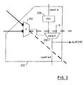
- An expanded diagram of a comparison unit is shown in FIG. 2 . It is the job of each block to compare the values of the two input bytes, tally up the count of matched bytes, and report a winning match to control logic.
- a comparison unit 200 in the matrix 170 includes a byte comparator 210 arranged to receive for comparison a byte value from the input buffer byte position for that row and a history buffer byte value passed from a unit diagonally left and above.
- An incrementer 220 is arranged to receive and increment by '1' a 'count in' value from a unit directly above in the same column of the matrix.
- a selector 230 is arranged to receive the incremented count value and a ⁇ 0' value and to select between these in dependence on the output of the comparator 210. If the comparator 210 indicates a match, the selector 230 outputs the incremented count value; otherwise it outputs a '0' value.
- the output of the selector is passed as a 'count out' value to a unit directly below in the same column; the selector output is also passed to MFPE for the same row of the matrix.
- the byte values input to the selector 210 are passed to a unit directly to the right in the same row and to a unit diagonally below and right.
- FIG. 2 shows that in addition to the byte to be compared, the unit 200 takes as input the "count" from the unit above, which indicates the length of the string seen thus far, and the byte for the same row of the input buffer 140. If the two input bytes match, then the comparison unit will increment that count, and pass the new count to the unit below it. If the two bytes do not match then the output count will be set to zero, regardless of the input count value.
- the value of this count is also output from the right-hand side of each comparison unit, and is fed to the "MAX Function/Priority Encoder" (MFPE) logic 150 at the end of the row.
- MFPE MAX Function/Priority Encoder
- the function of the MFPE is to decide which comparison unit(s) 200 of the 512 in that row reported the longest string (i.e., the largest count - the MAX function), and to encode the position within the row. If more than one column produces the same large count then the MFPE encodes (arbitrarily) the left-most value (the priority encoding function).
- the value produced by the MFPE is not necessarily the string that will be encoded, as the string may continue beyond that row.
- the largest string values for each row (reported by the MFPE 150) and their encoded positions are fed to the Token Encoder (TE) 160.
- the TE examines the reported lengths for each row, and decides where strings can be encoded for this batch of 12 input bytes. Where strings are to be encoded, the TE uses the positions reported by the MFPE as part of the token, along with the string length. Note that the length may rise to more than 12, when a long string spans more than one cycle. When this happens, the count is accumulated in the TE, ready for coding when the string terminates.
- the TE must output literals. For this the TE takes data directly from the input buffer 140.
- FIG. 3 shows a snapshot of a compression operation 300.
- the previous sentence is used as input, and for simplicity only 5 input bytes and 27 history buffer bytes are shown.
- the filled circles indicate where a match is detected; a useful string match can be seen at column 320 in the current input bytes "ion". It is the position of column 320 in the row that will be forwarded for encoding.
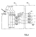
- the comparison unit 400 (which as illustrated is a unit of row 3 of the matrix 170) has a comparator 410 which receives the two byte values to be compared as described above.
- Three AND gates 422, 424 and 426 each have one of their inputs connected to receive the output of the comparator 410, and have their other inputs connected to receive respective ones of three bit lines (carrying a 3-bit 'input count' value) from a comparison unit directly above in the same column.
- the outputs of the AND gates 422, 424 and 426, together with the output of the comparator 410, (carrying a 4-bit 'output count' value) are connected to a comparison unit directly below in the same column.
- the leftmost three of the 'output count' bit lines are connected respectively to inputs of three AND gates 432, 434 and 436.
- the outputs of the AND gates 432, 434 and 436, together with the output of the AND gate 426, are connected to inputs of a 4-input OR gate 440.
- the output of the OR gate 440 (together with outputs of the other comparison units 400 in row 3 of the matrix 170) are connected, within an MFPE 500, to inputs of a 512-input priority encoder 510. Also within the MFPE 500, the outputs of the AND gates 422, 424 and 426 are connected (together with outputs of AND gates of other comparison units 400 in row 3 of the matrix 170) to respective inputs of 512-input OR gates 522, 524 and 526. the outputs of the OR gates 522, 524 and 526 are connected invertedly to inputs of the AND gates 432, 434 and 436 in each of the comparison units 400 in row 3 of the matrix 170.
- the comparator 410 is the same as the comparator 210 in the comparison unit 200 described above, but in the comparison unit 400 the "count” is maintained by an N-bit vector.
- the bits of this vector are numbered 1 to N, and a count of "n” is represented by bits 1 to n being '1'. All other bits in the vector are ⁇ 0'. Thus, a count of zero is shown by all bits being zero. This is a useful method of counting in this design because:
- the priority encoder is made simple also.
- the input count is represented by a 3-bit vector, which can indicate 4 values: Vector Indicated Value Indicated Match 000 zero 100 one match in this column in row 2 110 two match in this column in rows 1 and 2 111 more than two match in this column in rows 1 and 2, and a carry
- the comparator 410 detects a match in this column in this row (row 3), it will increment the count, producing a 4-bit vector 'output count' from the bottom of the unit. The incrementation will be achieved by effectively shifting the input vector right by one bit, adding a '1' at the left. If there is no match here, the AND gates 422, 424 and 426 are all turned off and the 'output count' collapses to zero.
- a modified version of the 4-bit count is output to logic circuitry 510, 522, 524 and 526 in the MFPE 500 at the end of the row, also shown in FIG. 4 .
- the three 512-input OR gates 522, 524 and 526 decide the maximum count for this row (the low-order bit is not used as it represents a count of only 1 byte). This maximum value is used to disqualify all counts smaller than the winning count, by means of AND gates 432, 434 and 436 in the comparison units 400 of the columns that do not contribute this maximum count.
- Those comparison units that show the maximum counts declare their candidacy on the encoder input, and the priority encoder codes the position of the leftmost of them.
- the "win" outputs of OR gates 440 in the comparison units of the bottom row comprise the 512 "carry" bits to be stored for the next cycle.
- the critical timing path - producing a valid carry for the next cycle - consists in this case of up to 12 AND gates (from a string of 12 matches), through a 512-input OR gate (which probably has several cascaded gates) and then through two more AND gates for the carry.
- a total of some 20 gate delays determines the maximum operating frequency for this design.
- the 12 AND gate delays may be reduced by using look-ahead techniques, although this adds to the gate count.
- comparison units 400 in the lower rows of the matrix 170 have proportionally more gates, and so it can be understood that the total number of gates increases with the square of the number of bytes processed per cycle.
- an LZ1 compressor may be constructed that can process an arbitrary number of bytes per cycle, limited by gate count and timing considerations.
- the data compression technique described above has the advantage that it is expandable to any number of bytes per cycle, or any length of history buffer, and so can provide operation at any desired bandwidth (limited only by gate count and timing considerations as noted above).
Landscapes
- Engineering & Computer Science (AREA)
- Theoretical Computer Science (AREA)
- Compression, Expansion, Code Conversion, And Decoders (AREA)
Claims (10)
- Anordnung (100) für eine LZ1-Kompression einer Datenkette, wobei die Anordnung Folgendes umfasst:ein Eingabepufferspeicher-Mittel (140), um eine erste Folge von Bytes der Datenkette zu halten;ein Verlaufspufferspeicher-Mittel (120), um eine zweite Folge von Bytes der Datenkette zu halten;ein Matrix-Vergleichsmittel (170), das mit dem Eingabepufferspeicher-Mittel (140) und dem Verlaufspufferspeicher-Mittel (120) verbunden ist und über eine Vielzahl von Zeilen und Spalten vonVergleichseinheiten (200) verfügt, um in dem Eingabepufferspeicher-Mittel (140) gehaltene Bytes mit Bytes zu vergleichen, die in dem Verlaufspufferspeicher-Mittel (120) gehalten werden, wobei die Bytes des Verlaufspufferspeicher-Mittels (120) mit diagonal versetzten Vergleichseinheiten (200) in dem Matrix-Vergleichsmittel (170) verbunden sind;dadurch gekennzeichnet, dass die Anordnung des Weiteren Folgendes umfasst:ein Erkennungsmittel (150), um in jeder der Zeilen diejenige Spalte zu erkennen, in der eine größte Zahl von aufeinander folgenden Byte-Übereinstimmungen an der Vergleichseinheit (200) in dieser Zeile und an ein Mittel (160), um eine Folge von übereinstimmenden Bytes, die von dem Erkennungsmittel (150) erkannt worden sind, als einen digitalen Schlüssel (Token) zu codieren.
- Anordnung nach Anspruch 1, wobei:das Matrix-Vergleichsmittel (170) Zählmittel (220, 230) umfasst, um an jeder Vergleichseinheit (200) einen Zählstand der Anzahl der aufeinander folgenden Byte-Übereinstimmungen zu erzeugen, die an der Vergleichseinheit (200) und an vorhergehenden Vergleichseinheiten (200) in derselben Spalte auftreten; unddas Erkennungsmittel (150) ein Mittel umfasst, um in jeder Zeile eine Spalte zu erkennen, in der der höchste Zählstand auftritt.
- Anordnung nach Anspruch 2, wobei jede Vergleichseinheit (200) Folgendes umfasst:ein Komparator-Mittel (210), um Bytes von dem Eingabepufferspeicher-Mittel (140) und von dem Verlaufspufferspeicher-Mittel (120) zu vergleichen;ein Inkrementierer-Mittel (220), um einen Zählwert von einer anderen Vergleichseinheit (200) in derselben Spalte zu empfangen und zu erhöhen; undein Auswahlmittel (230), um die Ausgabe des Komparator-Mittels (210) zu empfangen und um in Abhängigkeit davon die Ausgabe des Inkrementierer-Mittels (220) oder einen Null-Wert zur Weitergabe an eine andere Vergleichseinheit (200) in derselben Spalte auszuwählen.
- Anordnung nach Anspruch 2, wobei jede Vergleichseinheit (400) Folgendes umfasst:ein Komparator-Mittel (410), um Bytes von dem Eingabepufferspeicher-Mittel (140) und von dem Verlaufspufferspeicher-Mittel (120) zu vergleichen;Logikmittel (422, 424, 426), um einen Wert zu empfangen, der mehrere Bits hat, die einen Zählwert von einer anderen Vergleichseinheit in derselben Spalte darstellen, und um die Ausgabe des Komparator-Mittels (410) zu empfangen und um in Abhängigkeit davon den Wert auf Null zu setzen oder den Wert zu erhöhen, indem ein Bit verschoben und dem Wert ein weiteres Bit hinzugefügt wird.
- Verfahren für eine LZ1-Kompression einer Datenkette, das die folgenden Schritte durchführt:Halten einer ersten Folge von Bytes der Datenkette in einem Eingabepufferspeicher (140);Halten einer zweiten Folge von Bytes der Datenkette in einem Verlaufspufferspeicher (120);in dem Matrix-Vergleichsmittel (170), das mit dem Eingabepufferspeicher (140) und dem Verlaufspufferspeicher (120) verbunden ist und über eine Vielzahl von Zeilen und Spalten von Vergleichseinheiten (200) verfügt, Vergleichen von Bytes, die in dem Eingabepufferspeicher (140) gehalten werden, mit Bytes, die in dem Verlaufspufferspeicher (120) gehalten werden, wobei Bytes des Verlaufspufferspeichers (120) mit diagonal versetzten Vergleichseinheiten (200) in dem Matrix-Vergleichsmittel (170) verbunden sind;dadurch gekennzeichnet, dass das Verfahren des Weiteren die folgenden Schritte durchführt:Erkennen von derjenigen Spalte in jeder der Zeilen, in der eine größte Zahl von aufeinander folgenden Byte-Übereinstimmungen an der Vergleichseinheit (200) in dieser Zeile und an vorhergehenden Vergleichseinheiten (200) in derselben Spalte aufgetreten ist; undCodieren einer Folge von übereinstimmenden Bytes, die in dem Schritt des Erkennens erkannt worden sind, als einen digitalen Schlüssel (Token).
- Verfahren nach Anspruch 5, wobei:der Schritt des Vergleichens das Erzeugen eines Zählstands der Anzahl von aufeinander folgenden Byte-Übereinstimmungen an jeder Vergleichseinheit (200) umfasst, welche an der Vergleichseinheit (200) und an vorhergehenden Vergleichseinheiten (200) in derselben Spalte auftreten; undder Schritt des Erkennens in jeder Zeile das Erkennen einer Spalte umfasst, in der der höchste Zählstand auftritt.
- Verfahren nach Anspruch 6, wobei der Schritt des Vergleichens an jeder Vergleichseinheit (200) Folgendes umfasst:in dem Komparator-Mittel (210) Vergleichen von Bytes von dem Eingabepufferspeicher (140) und von dem Verlaufspufferspeicher (120);in dem Inkrementierer-Mittel (220) Erhöhen eines Zählwerts, der von einer anderen Vergleichseinheit (200) in derselben Spalte empfangen wurde; undin Abhängigkeit von der Ausgabe des Komparator-Mittels (210) Auswählen der Ausgabe des Inkrementierer-Mittels (220) oder eines Null-Werts zur Weitergabe an eine andere Vergleichseinheit (200) in derselben Spalte.
- Verfahren nach Anspruch 6, wobei der Schritt des Vergleichens an jeder Vergleichseinheit (200) Folgendes umfasst:in dem Komparator-Mittel (410) Vergleichen von Bytes von dem Eingabepufferspeicher (140) und von dem Verlaufspufferspeicher (120);Empfangen eines Werts, der mehrere Bits hat, die einen Zählwert von einer anderen Vergleichseinheit in derselben Spalte darstellen, Empfangen der Ausgabe des Komparator-Mittels (410) und in Abhängigkeit davon Setzen des Werts auf Null oder Erhöhen des Werts, indem ein Bit verschoben und dem Wert ein weiteres Bit hinzugefügt wird.
- Verfahren nach einem der Ansprüche 5 bis 8, wobei der Verlaufspufferspeicher (120) Folgendes umfasst:ein erstes Schieberegister-Mittel, das mit Vergleichseinheiten (200) in einer Zeile an einer ersten Seite des Matrix-Vergleichsmittels (170) verbunden ist,undein zweites Schieberegister-Mittel, das mit Vergleichseinheiten (200) in einer Zeile an einer zweiten Seite des Matrix-Vergleichsmittels (170) gegenüber der ersten Seite verbunden ist.
- Integrierte Schaltung, die die Anordnung nach einem der Ansprüche 1 bis 4 umfasst.
Applications Claiming Priority (3)
| Application Number | Priority Date | Filing Date | Title |
|---|---|---|---|
| GB0210604 | 2002-05-09 | ||
| GBGB0210604.5A GB0210604D0 (en) | 2002-05-09 | 2002-05-09 | Method and arrangement for data compression |
| PCT/GB2003/000384 WO2003096543A1 (en) | 2002-05-09 | 2003-01-30 | Method and arrangement for data compression according to the lz77 algorithm |
Publications (2)
| Publication Number | Publication Date |
|---|---|
| EP1506619A1 EP1506619A1 (de) | 2005-02-16 |
| EP1506619B1 true EP1506619B1 (de) | 2011-07-27 |
Family
ID=9936342
Family Applications (1)
| Application Number | Title | Priority Date | Filing Date |
|---|---|---|---|
| EP03702716A Expired - Lifetime EP1506619B1 (de) | 2002-05-09 | 2003-01-30 | Methode und vorrichtung zur datenkomprimierung für den lz1 algorithmus |
Country Status (12)
| Country | Link |
|---|---|
| US (1) | US7233265B2 (de) |
| EP (1) | EP1506619B1 (de) |
| JP (1) | JP3989933B2 (de) |
| KR (1) | KR100702428B1 (de) |
| CN (1) | CN1309174C (de) |
| AT (1) | ATE518308T1 (de) |
| AU (1) | AU2003205839A1 (de) |
| CA (1) | CA2485566C (de) |
| GB (1) | GB0210604D0 (de) |
| IL (1) | IL164722A0 (de) |
| PL (1) | PL371971A1 (de) |
| WO (1) | WO2003096543A1 (de) |
Families Citing this family (31)
| Publication number | Priority date | Publication date | Assignee | Title |
|---|---|---|---|---|
| GB0102572D0 (en) * | 2001-02-01 | 2001-03-21 | Btg Int Ltd | Apparatus to provide fast data compression |
| GB0315152D0 (en) | 2003-06-28 | 2003-08-06 | Ibm | Data parsing and tokenizing apparatus,method and program |
| CA2609863C (en) | 2005-06-03 | 2014-02-18 | The Commonwealth Of Australia | Messaging method |
| US7180433B1 (en) * | 2005-09-22 | 2007-02-20 | Tandberg Storage Asa | Fast data compression and decompression system and method |
| EP2541431A1 (de) | 2005-10-07 | 2013-01-02 | Altera Corporation | Dateneingabe für systolische Arrayprozessoren |
| CN100385437C (zh) * | 2005-11-10 | 2008-04-30 | 浙江中控技术股份有限公司 | 实时数据压缩方法 |
| US8085171B2 (en) * | 2006-03-24 | 2011-12-27 | University Of Mississippi | High-speed data compression based on set associative cache mapping techniques |
| CN101449462A (zh) * | 2006-03-24 | 2009-06-03 | 密西西比大学 | 基于集合关联高速缓存映射技术的高速数据压缩 |
| WO2009105332A1 (en) * | 2008-02-18 | 2009-08-27 | Sandbridge Technologies, Inc. | Method to accelerate null-terminated string operations |
| US8667046B2 (en) * | 2008-02-21 | 2014-03-04 | Ecole Polytechnique Federale De Lausanne/Service Des Relations Industrielles | Generalized programmable counter arrays |
| US8013762B2 (en) * | 2009-11-03 | 2011-09-06 | Seagate Technology Llc | Evaluating alternative encoding solutions during data compression |
| US8248279B2 (en) * | 2010-10-26 | 2012-08-21 | Hewlett-Packard Development Company, L.P. | History buffer apparatus and method for adaptive lossless data compression |
| US8824569B2 (en) | 2011-12-07 | 2014-09-02 | International Business Machines Corporation | High bandwidth decompression of variable length encoded data streams |
| US8918408B2 (en) * | 2012-08-24 | 2014-12-23 | Microsoft Corporation | Candidate generation for predictive input using input history |
| US8766827B1 (en) * | 2013-03-15 | 2014-07-01 | Intel Corporation | Parallel apparatus for high-speed, highly compressed LZ77 tokenization and Huffman encoding for deflate compression |
| CN104113344B (zh) * | 2013-04-16 | 2017-04-12 | 晨星半导体股份有限公司 | 解压缩电路与相关的压缩方法与解压缩方法 |
| US9374106B2 (en) | 2013-08-28 | 2016-06-21 | International Business Machines Corporation | Efficient context save/restore during hardware decompression of DEFLATE encoded data |
| US8933824B1 (en) | 2013-08-28 | 2015-01-13 | International Business Machines Corporation | Hardware decompression of deflate encoded data with multiple blocks |
| US9800640B2 (en) | 2013-10-02 | 2017-10-24 | International Business Machines Corporation | Differential encoder with look-ahead synchronization |
| US9634689B2 (en) * | 2014-08-20 | 2017-04-25 | Sunedison Semiconductor Limited (Uen201334164H) | Method and system for arranging numeric data for compression |
| US9524169B2 (en) * | 2014-09-24 | 2016-12-20 | Intel Corporation | Technologies for efficient LZ77-based data decompression |
| US9537504B1 (en) * | 2015-09-25 | 2017-01-03 | Intel Corporation | Heterogeneous compression architecture for optimized compression ratio |
| US9450606B1 (en) | 2015-10-01 | 2016-09-20 | Seagate Technology Llc | Data matching for hardware data compression |
| CN105610447B (zh) * | 2015-10-29 | 2018-06-19 | 吴均 | 基于lz77算法的分区编码压缩方法 |
| US9864549B2 (en) | 2016-02-29 | 2018-01-09 | Avago Technologies General Ip (Singapore) Pte. Ltd. | Systems and methods for high throughput multi-input compression |
| CN108809320B (zh) * | 2017-04-28 | 2021-05-18 | 华为技术有限公司 | 一种基于lz77的数据压缩方法、设备及终端 |
| US10678506B2 (en) * | 2017-08-01 | 2020-06-09 | Arm Limited | Matching consecutive values in a data processing apparatus |
| US11042375B2 (en) | 2017-08-01 | 2021-06-22 | Arm Limited | Counting elements in data items in a data processing apparatus |
| JP7562440B2 (ja) | 2021-02-09 | 2024-10-07 | キオクシア株式会社 | 文字列検索装置及びメモリシステム |
| CN114956290B (zh) * | 2022-07-27 | 2022-11-01 | 江苏赛沐思环保科技有限公司 | 一种基于lz77编码的工业废水的智能处理方法 |
| US12197419B2 (en) * | 2022-09-14 | 2025-01-14 | Sap Se | Consistency checks for compressed data |
Family Cites Families (17)
| Publication number | Priority date | Publication date | Assignee | Title |
|---|---|---|---|---|
| US4965569A (en) * | 1987-06-30 | 1990-10-23 | Motorola, Inc. | Digitized stored voice paging receiver |
| JPH0813635B2 (ja) * | 1987-12-03 | 1996-02-14 | 安全自動車株式会社 | 車両の制動性能測定方法 |
| US5146221A (en) * | 1989-01-13 | 1992-09-08 | Stac, Inc. | Data compression apparatus and method |
| US5179378A (en) * | 1991-07-30 | 1993-01-12 | University Of South Florida | Method and apparatus for the compression and decompression of data using Lempel-Ziv based techniques |
| JP2819906B2 (ja) * | 1991-12-27 | 1998-11-05 | 住友金属工業株式会社 | 室温および高温強度に優れた工具用Ni基合金 |
| CN1099766C (zh) * | 1994-06-16 | 2003-01-22 | 精工爱普生株式会社 | 数据压缩方法、数据复原方法及信息处理装置 |
| US5608396A (en) * | 1995-02-28 | 1997-03-04 | International Business Machines Corporation | Efficient Ziv-Lempel LZI data compression system using variable code fields |
| US5771010A (en) * | 1995-03-22 | 1998-06-23 | Ibm Corporation | Apparatus for compressing data using a Lempel-Ziv-type algorithm |
| US5805086A (en) * | 1995-10-10 | 1998-09-08 | International Business Machines Corporation | Method and system for compressing data that facilitates high-speed data decompression |
| US5771011A (en) * | 1996-07-15 | 1998-06-23 | International Business Machines Corporation | Match detect logic for multi-byte per cycle hardware data compression |
| JP3540109B2 (ja) * | 1996-12-24 | 2004-07-07 | 富士通株式会社 | データ圧縮方法及び装置 |
| US5874908A (en) * | 1997-09-19 | 1999-02-23 | International Business Machines Corporation | Method and apparatus for encoding Lempel-Ziv 1 variants |
| US6885319B2 (en) * | 1999-01-29 | 2005-04-26 | Quickshift, Inc. | System and method for generating optimally compressed data from a plurality of data compression/decompression engines implementing different data compression algorithms |
| EP1148649A1 (de) * | 2000-04-17 | 2001-10-24 | I-Data International A/S | Verfahren und Vorrichtung zur Datenkompression |
| US6657565B2 (en) * | 2002-03-21 | 2003-12-02 | International Business Machines Corporation | Method and system for improving lossless compression efficiency |
| GB0210602D0 (en) | 2002-05-09 | 2002-06-19 | Ibm | Circuit and method for use in data compression |
| GB0213687D0 (en) * | 2002-06-14 | 2002-07-24 | Ibm | Multi-byte lempel-ziv 1 (LZ1) decompression |
-
2002
- 2002-05-09 GB GBGB0210604.5A patent/GB0210604D0/en not_active Ceased
-
2003
- 2003-01-30 CA CA002485566A patent/CA2485566C/en not_active Expired - Lifetime
- 2003-01-30 EP EP03702716A patent/EP1506619B1/de not_active Expired - Lifetime
- 2003-01-30 JP JP2004504391A patent/JP3989933B2/ja not_active Expired - Fee Related
- 2003-01-30 AU AU2003205839A patent/AU2003205839A1/en not_active Abandoned
- 2003-01-30 CN CNB038009889A patent/CN1309174C/zh not_active Expired - Fee Related
- 2003-01-30 KR KR1020047017465A patent/KR100702428B1/ko not_active Expired - Fee Related
- 2003-01-30 US US10/513,263 patent/US7233265B2/en not_active Expired - Fee Related
- 2003-01-30 PL PL03371971A patent/PL371971A1/xx unknown
- 2003-01-30 AT AT03702716T patent/ATE518308T1/de not_active IP Right Cessation
- 2003-01-30 WO PCT/GB2003/000384 patent/WO2003096543A1/en not_active Ceased
-
2004
- 2004-10-20 IL IL16472204A patent/IL164722A0/xx unknown
Also Published As
| Publication number | Publication date |
|---|---|
| WO2003096543A1 (en) | 2003-11-20 |
| KR100702428B1 (ko) | 2007-04-04 |
| US7233265B2 (en) | 2007-06-19 |
| US20050179569A1 (en) | 2005-08-18 |
| CA2485566A1 (en) | 2003-11-20 |
| ATE518308T1 (de) | 2011-08-15 |
| IL164722A0 (en) | 2005-12-18 |
| CN1552127A (zh) | 2004-12-01 |
| AU2003205839A1 (en) | 2003-11-11 |
| KR20040104675A (ko) | 2004-12-10 |
| GB0210604D0 (en) | 2002-06-19 |
| PL371971A1 (en) | 2005-07-11 |
| JP2005525039A (ja) | 2005-08-18 |
| EP1506619A1 (de) | 2005-02-16 |
| JP3989933B2 (ja) | 2007-10-10 |
| CN1309174C (zh) | 2007-04-04 |
| CA2485566C (en) | 2008-05-13 |
Similar Documents
| Publication | Publication Date | Title |
|---|---|---|
| CA2485566C (en) | Method and arrangement for data compression according to the lz7 algorithm | |
| US5179378A (en) | Method and apparatus for the compression and decompression of data using Lempel-Ziv based techniques | |
| US9054729B2 (en) | System and method of compression and decompression | |
| US7161507B2 (en) | Fast, practically optimal entropy coding | |
| US20010051941A1 (en) | Searching method of block sorting lossless compressed data, and encoding method suitable for searching data in block sorting lossless compressed data | |
| US20040022312A1 (en) | Lossless data compression | |
| KR20020075889A (ko) | 보다 효율적인 데이터 압축 | |
| EP1508200B1 (de) | Methode und vorrichtung zur parallelen datenkomprimierung nach dem lz77 algorithmus | |
| US20040264696A1 (en) | Data parsing and tokenizing apparatus, method and program | |
| EP0435802B1 (de) | Verfahren zur Dekomprimierung von komprimierten Daten | |
| EP0438954B1 (de) | Verfahren zur Dekodierung komprimierter Daten | |
| JP4000266B2 (ja) | データ符号化装置、データ符号化方法、及びそのプログラム | |
| US7109895B1 (en) | High performance Lempel Ziv compression architecture | |
| Mehboob et al. | High speed lossless data compression architecture | |
| US9344113B1 (en) | Lempel Ziv compression architecture | |
| Chen et al. | VLSI design for high-speed LZ-based data compression | |
| JPH05241775A (ja) | データ圧縮方式 | |
| Henriques et al. | A parallel architecture for data compression | |
| Mohey et al. | Design and implementation of Lempel-Ziv data compression using FPGA | |
| Liu et al. | An Efficient Direct Access Algorithm for Integer Compression | |
| JP3051501B2 (ja) | データ圧縮方法 | |
| Lee et al. | A novel PE-based architecture for lossless LZ compression | |
| JPH04330517A (ja) | デ−タ圧縮及び復元方法 |
Legal Events
| Date | Code | Title | Description |
|---|---|---|---|
| PUAI | Public reference made under article 153(3) epc to a published international application that has entered the european phase |
Free format text: ORIGINAL CODE: 0009012 |
|
| 17P | Request for examination filed |
Effective date: 20041209 |
|
| AK | Designated contracting states |
Kind code of ref document: A1 Designated state(s): AT BE BG CH CY CZ DE DK EE ES FI FR GB GR HU IE IT LI LU MC NL PT SE SI SK TR |
|
| AX | Request for extension of the european patent |
Extension state: AL LT LV MK RO |
|
| DAX | Request for extension of the european patent (deleted) | ||
| GRAP | Despatch of communication of intention to grant a patent |
Free format text: ORIGINAL CODE: EPIDOSNIGR1 |
|
| GRAS | Grant fee paid |
Free format text: ORIGINAL CODE: EPIDOSNIGR3 |
|
| GRAA | (expected) grant |
Free format text: ORIGINAL CODE: 0009210 |
|
| AK | Designated contracting states |
Kind code of ref document: B1 Designated state(s): AT BE BG CH CY CZ DE DK EE ES FI FR GB GR HU IE IT LI LU MC NL PT SE SI SK TR |
|
| REG | Reference to a national code |
Ref country code: GB Ref legal event code: FG4D |
|
| REG | Reference to a national code |
Ref country code: CH Ref legal event code: NV Representative=s name: IBM RESEARCH GMBH ZURICH RESEARCH LABORATORY INTEL Ref country code: CH Ref legal event code: EP |
|
| REG | Reference to a national code |
Ref country code: DE Ref legal event code: R084 Ref document number: 60337805 Country of ref document: DE |
|
| REG | Reference to a national code |
Ref country code: DE Ref legal event code: R096 Ref document number: 60337805 Country of ref document: DE Effective date: 20110915 |
|
| REG | Reference to a national code |
Ref country code: DE Ref legal event code: R084 Ref document number: 60337805 Country of ref document: DE Effective date: 20110804 Ref country code: DE Ref legal event code: R084 Ref document number: 60337805 Country of ref document: DE Effective date: 20110816 |
|
| REG | Reference to a national code |
Ref country code: NL Ref legal event code: VDEP Effective date: 20110727 |
|
| REG | Reference to a national code |
Ref country code: AT Ref legal event code: MK05 Ref document number: 518308 Country of ref document: AT Kind code of ref document: T Effective date: 20110727 |
|
| PG25 | Lapsed in a contracting state [announced via postgrant information from national office to epo] |
Ref country code: FI Free format text: LAPSE BECAUSE OF FAILURE TO SUBMIT A TRANSLATION OF THE DESCRIPTION OR TO PAY THE FEE WITHIN THE PRESCRIBED TIME-LIMIT Effective date: 20110727 Ref country code: BE Free format text: LAPSE BECAUSE OF FAILURE TO SUBMIT A TRANSLATION OF THE DESCRIPTION OR TO PAY THE FEE WITHIN THE PRESCRIBED TIME-LIMIT Effective date: 20110727 Ref country code: NL Free format text: LAPSE BECAUSE OF FAILURE TO SUBMIT A TRANSLATION OF THE DESCRIPTION OR TO PAY THE FEE WITHIN THE PRESCRIBED TIME-LIMIT Effective date: 20110727 Ref country code: PT Free format text: LAPSE BECAUSE OF FAILURE TO SUBMIT A TRANSLATION OF THE DESCRIPTION OR TO PAY THE FEE WITHIN THE PRESCRIBED TIME-LIMIT Effective date: 20111128 Ref country code: SE Free format text: LAPSE BECAUSE OF FAILURE TO SUBMIT A TRANSLATION OF THE DESCRIPTION OR TO PAY THE FEE WITHIN THE PRESCRIBED TIME-LIMIT Effective date: 20110727 |
|
| PG25 | Lapsed in a contracting state [announced via postgrant information from national office to epo] |
Ref country code: SI Free format text: LAPSE BECAUSE OF FAILURE TO SUBMIT A TRANSLATION OF THE DESCRIPTION OR TO PAY THE FEE WITHIN THE PRESCRIBED TIME-LIMIT Effective date: 20110727 Ref country code: GR Free format text: LAPSE BECAUSE OF FAILURE TO SUBMIT A TRANSLATION OF THE DESCRIPTION OR TO PAY THE FEE WITHIN THE PRESCRIBED TIME-LIMIT Effective date: 20111028 Ref country code: AT Free format text: LAPSE BECAUSE OF FAILURE TO SUBMIT A TRANSLATION OF THE DESCRIPTION OR TO PAY THE FEE WITHIN THE PRESCRIBED TIME-LIMIT Effective date: 20110727 Ref country code: CY Free format text: LAPSE BECAUSE OF FAILURE TO SUBMIT A TRANSLATION OF THE DESCRIPTION OR TO PAY THE FEE WITHIN THE PRESCRIBED TIME-LIMIT Effective date: 20110727 |
|
| PG25 | Lapsed in a contracting state [announced via postgrant information from national office to epo] |
Ref country code: CZ Free format text: LAPSE BECAUSE OF FAILURE TO SUBMIT A TRANSLATION OF THE DESCRIPTION OR TO PAY THE FEE WITHIN THE PRESCRIBED TIME-LIMIT Effective date: 20110727 Ref country code: SK Free format text: LAPSE BECAUSE OF FAILURE TO SUBMIT A TRANSLATION OF THE DESCRIPTION OR TO PAY THE FEE WITHIN THE PRESCRIBED TIME-LIMIT Effective date: 20110727 |
|
| PGFP | Annual fee paid to national office [announced via postgrant information from national office to epo] |
Ref country code: FR Payment date: 20120130 Year of fee payment: 10 |
|
| PG25 | Lapsed in a contracting state [announced via postgrant information from national office to epo] |
Ref country code: IT Free format text: LAPSE BECAUSE OF FAILURE TO SUBMIT A TRANSLATION OF THE DESCRIPTION OR TO PAY THE FEE WITHIN THE PRESCRIBED TIME-LIMIT Effective date: 20110727 Ref country code: EE Free format text: LAPSE BECAUSE OF FAILURE TO SUBMIT A TRANSLATION OF THE DESCRIPTION OR TO PAY THE FEE WITHIN THE PRESCRIBED TIME-LIMIT Effective date: 20110727 |
|
| PLBE | No opposition filed within time limit |
Free format text: ORIGINAL CODE: 0009261 |
|
| STAA | Information on the status of an ep patent application or granted ep patent |
Free format text: STATUS: NO OPPOSITION FILED WITHIN TIME LIMIT |
|
| PG25 | Lapsed in a contracting state [announced via postgrant information from national office to epo] |
Ref country code: DK Free format text: LAPSE BECAUSE OF FAILURE TO SUBMIT A TRANSLATION OF THE DESCRIPTION OR TO PAY THE FEE WITHIN THE PRESCRIBED TIME-LIMIT Effective date: 20110727 |
|
| 26N | No opposition filed |
Effective date: 20120502 |
|
| REG | Reference to a national code |
Ref country code: DE Ref legal event code: R097 Ref document number: 60337805 Country of ref document: DE Effective date: 20120502 |
|
| PG25 | Lapsed in a contracting state [announced via postgrant information from national office to epo] |
Ref country code: MC Free format text: LAPSE BECAUSE OF NON-PAYMENT OF DUE FEES Effective date: 20120131 |
|
| REG | Reference to a national code |
Ref country code: CH Ref legal event code: PL |
|
| REG | Reference to a national code |
Ref country code: IE Ref legal event code: MM4A |
|
| PG25 | Lapsed in a contracting state [announced via postgrant information from national office to epo] |
Ref country code: CH Free format text: LAPSE BECAUSE OF NON-PAYMENT OF DUE FEES Effective date: 20120131 Ref country code: LI Free format text: LAPSE BECAUSE OF NON-PAYMENT OF DUE FEES Effective date: 20120131 |
|
| PG25 | Lapsed in a contracting state [announced via postgrant information from national office to epo] |
Ref country code: IE Free format text: LAPSE BECAUSE OF NON-PAYMENT OF DUE FEES Effective date: 20120130 |
|
| PG25 | Lapsed in a contracting state [announced via postgrant information from national office to epo] |
Ref country code: ES Free format text: LAPSE BECAUSE OF FAILURE TO SUBMIT A TRANSLATION OF THE DESCRIPTION OR TO PAY THE FEE WITHIN THE PRESCRIBED TIME-LIMIT Effective date: 20111107 |
|
| PG25 | Lapsed in a contracting state [announced via postgrant information from national office to epo] |
Ref country code: BG Free format text: LAPSE BECAUSE OF FAILURE TO SUBMIT A TRANSLATION OF THE DESCRIPTION OR TO PAY THE FEE WITHIN THE PRESCRIBED TIME-LIMIT Effective date: 20111027 |
|
| REG | Reference to a national code |
Ref country code: FR Ref legal event code: ST Effective date: 20130930 |
|
| PG25 | Lapsed in a contracting state [announced via postgrant information from national office to epo] |
Ref country code: FR Free format text: LAPSE BECAUSE OF NON-PAYMENT OF DUE FEES Effective date: 20130131 |
|
| PG25 | Lapsed in a contracting state [announced via postgrant information from national office to epo] |
Ref country code: TR Free format text: LAPSE BECAUSE OF FAILURE TO SUBMIT A TRANSLATION OF THE DESCRIPTION OR TO PAY THE FEE WITHIN THE PRESCRIBED TIME-LIMIT Effective date: 20110727 |
|
| PG25 | Lapsed in a contracting state [announced via postgrant information from national office to epo] |
Ref country code: LU Free format text: LAPSE BECAUSE OF NON-PAYMENT OF DUE FEES Effective date: 20120130 |
|
| PG25 | Lapsed in a contracting state [announced via postgrant information from national office to epo] |
Ref country code: HU Free format text: LAPSE BECAUSE OF FAILURE TO SUBMIT A TRANSLATION OF THE DESCRIPTION OR TO PAY THE FEE WITHIN THE PRESCRIBED TIME-LIMIT Effective date: 20030130 |
|
| PGFP | Annual fee paid to national office [announced via postgrant information from national office to epo] |
Ref country code: DE Payment date: 20201223 Year of fee payment: 19 |
|
| REG | Reference to a national code |
Ref country code: DE Ref legal event code: R082 Ref document number: 60337805 Country of ref document: DE Representative=s name: KUISMA, SIRPA, FI |
|
| PGFP | Annual fee paid to national office [announced via postgrant information from national office to epo] |
Ref country code: GB Payment date: 20220126 Year of fee payment: 20 |
|
| REG | Reference to a national code |
Ref country code: DE Ref legal event code: R119 Ref document number: 60337805 Country of ref document: DE |
|
| PG25 | Lapsed in a contracting state [announced via postgrant information from national office to epo] |
Ref country code: DE Free format text: LAPSE BECAUSE OF NON-PAYMENT OF DUE FEES Effective date: 20220802 |
|
| REG | Reference to a national code |
Ref country code: GB Ref legal event code: PE20 Expiry date: 20230129 |
|
| PG25 | Lapsed in a contracting state [announced via postgrant information from national office to epo] |
Ref country code: GB Free format text: LAPSE BECAUSE OF EXPIRATION OF PROTECTION Effective date: 20230129 |