EP1506794A2 - Valve - Google Patents
Valve Download PDFInfo
- Publication number
- EP1506794A2 EP1506794A2 EP04026737A EP04026737A EP1506794A2 EP 1506794 A2 EP1506794 A2 EP 1506794A2 EP 04026737 A EP04026737 A EP 04026737A EP 04026737 A EP04026737 A EP 04026737A EP 1506794 A2 EP1506794 A2 EP 1506794A2
- Authority
- EP
- European Patent Office
- Prior art keywords
- valve
- valve member
- chamber
- pressure
- outlet
- Prior art date
- Legal status (The legal status is an assumption and is not a legal conclusion. Google has not performed a legal analysis and makes no representation as to the accuracy of the status listed.)
- Withdrawn
Links
- 230000002093 peripheral effect Effects 0.000 claims description 6
- 230000004044 response Effects 0.000 claims description 6
- 230000009467 reduction Effects 0.000 claims description 5
- 230000029058 respiratory gaseous exchange Effects 0.000 abstract description 8
- 230000007246 mechanism Effects 0.000 abstract description 4
- 230000001105 regulatory effect Effects 0.000 abstract description 2
- 239000003570 air Substances 0.000 description 8
- 230000009471 action Effects 0.000 description 7
- 230000000694 effects Effects 0.000 description 3
- 239000012080 ambient air Substances 0.000 description 2
- 230000006835 compression Effects 0.000 description 2
- 238000007906 compression Methods 0.000 description 2
- 230000001276 controlling effect Effects 0.000 description 2
- 239000000463 material Substances 0.000 description 2
- 230000000241 respiratory effect Effects 0.000 description 2
- 238000013022 venting Methods 0.000 description 2
- 230000015572 biosynthetic process Effects 0.000 description 1
- 230000009172 bursting Effects 0.000 description 1
- 238000006243 chemical reaction Methods 0.000 description 1
- 230000000295 complement effect Effects 0.000 description 1
- 238000010276 construction Methods 0.000 description 1
- 238000001816 cooling Methods 0.000 description 1
- 230000008878 coupling Effects 0.000 description 1
- 238000010168 coupling process Methods 0.000 description 1
- 238000005859 coupling reaction Methods 0.000 description 1
- 230000009189 diving Effects 0.000 description 1
- 231100001261 hazardous Toxicity 0.000 description 1
- 239000004810 polytetrafluoroethylene Substances 0.000 description 1
- 229920001343 polytetrafluoroethylene Polymers 0.000 description 1
- 229920002379 silicone rubber Polymers 0.000 description 1
- 239000004945 silicone rubber Substances 0.000 description 1
- 229910001220 stainless steel Inorganic materials 0.000 description 1
- 239000010935 stainless steel Substances 0.000 description 1
- 238000009423 ventilation Methods 0.000 description 1
Images
Classifications
-
- A—HUMAN NECESSITIES
- A62—LIFE-SAVING; FIRE-FIGHTING
- A62B—DEVICES, APPARATUS OR METHODS FOR LIFE-SAVING
- A62B9/00—Component parts for respiratory or breathing apparatus
- A62B9/02—Valves
- A62B9/022—Breathing demand regulators
-
- B—PERFORMING OPERATIONS; TRANSPORTING
- B63—SHIPS OR OTHER WATERBORNE VESSELS; RELATED EQUIPMENT
- B63C—LAUNCHING, HAULING-OUT, OR DRY-DOCKING OF VESSELS; LIFE-SAVING IN WATER; EQUIPMENT FOR DWELLING OR WORKING UNDER WATER; MEANS FOR SALVAGING OR SEARCHING FOR UNDERWATER OBJECTS
- B63C11/00—Equipment for dwelling or working underwater; Means for searching for underwater objects
- B63C11/02—Divers' equipment
- B63C11/18—Air supply
- B63C11/22—Air supply carried by diver
- B63C11/2227—Second-stage regulators
Definitions
- the present invention relates to gas flow control valves and more particularly to demand valves for breathing apparatus.
- the invention is concerned with a valve incorporating a so-called “balanced piston” valve member, which is characterised by low operating forces and an ability to operate consistently over a range of supply pressures.
- a valve for use in underwater diving equipment is described and illustrated schematically in United States patent specification no. 3647175. It is an aim of the present invention to adapt this principle to use in a positive pressure demand valve of compact construction and efficient operation.
- a gas flow control valve comprising: an inlet chamber and an outlet chamber; an axially-slidable main valve member of tubular form, one end of which extends into the inlet chamber, the other end of which leads to the outlet chamber, and the interior of which defines a flow path to lead gas from the inlet chamber to the outlet chamber; a valve seat facing said valve member in the inlet chamber such that the spacing of the valve member from the seat controls the rate of gas flow through the valve member from the inlet chamber to the outlet chamber and contact of the valve member with the seat shuts off such flow; a bypass chamber on the opposite side of said seat to the main valve member; at least one inlet port opening from the inlet chamber to said bypass chamber; an outlet port opening from said bypass chamber through said valve seat at a position to communicate with the interior of the main valve member while the latter is seated; and a bypass valve member in said bypass chamber which normally isolates said outlet port from said inlet port but which can be displaced to permit
- a gas flow control valve comprising: an inlet chamber and an outlet chamber; a movable valve member for controlling the flow of pressurised gas from the inlet chamber to the outlet chamber; and a flexible pressure-responsive member sensitive to the gas pressure within the outlet chamber for controlling the movement of the valve member;
- the valve member being an axially-slidable member of tubular form, one end of which extends into the inlet chamber, the other end of which leads to the outlet chamber, and the interior of which defines a flow path to lead gas from the inlet chamber to the outlet chamber; a valve seat facing the valve member in the inlet chamber such that the spacing of the valve member from said seat controls the rate of gas flow through the valve member from the inlet chamber to the outlet chamber and contact of the valve member with said seat shuts off such flow; spring means acting upon the valve member to bias the same away from said seat; the axis of flexure of the pressure-responsive member being inclined to the axis of the valve member and mechanical linkage means being provided to link the pressure-responsive member
- said spring means constitutes the sole spring means acting upon said valve member, pressure-responsive member or mechanical linkage means, in normal operation of the valve.
- said pressure-responsive member comprises a flexible diaphragm bounding a portion of the outlet chamber and adapted to flex inwardly and outwardly of said chamber in response to reduction and increase of gas pressure within said chamber respectively; and said mechanical linkage means comprises a lever linked at one end to said diaphragm pivoted at the other end to a fixed part of the valve structure, and linked at an intermediate position to the valve member whereby to push the valve member towards said seat in response to outward flexure of said diaphragm.
- said valve further includes bypass valve means comprising: a bypass chamber on the opposite side of said valve seat to the valve member at least one inlet port opening from the inlet chamber to said bypass chamber; an outlet port opening from said bypass chamber through said valve seat at a position to communicate with the interior of the valve member while the latter is seated; and a bypass valve member in said bypass chamber which normally isolates said outlet port from said inlet port but which can be displaced to permit gas to flow from the inlet chamber to the interior of the first-mentioned valve member via said bypass chamber.
- bypass valve means comprising: a bypass chamber on the opposite side of said valve seat to the valve member at least one inlet port opening from the inlet chamber to said bypass chamber; an outlet port opening from said bypass chamber through said valve seat at a position to communicate with the interior of the valve member while the latter is seated; and a bypass valve member in said bypass chamber which normally isolates said outlet port from said inlet port but which can be displaced to permit gas to flow from the inlet chamber to the interior of the first-mentioned valve
- valve comprises manually-operable control means for displacing said bypass valve member.
- bypass valve member is in the form of a spring-biased piston which is adapted to be displaced by gas pressure communicated through said inlet port if an abnormally high pressure pertains in the inlet chamber while the first-mentioned valve member is seated.
- the pressure-responsive member comprises a diaphragm having a rigid central portion and a flexible peripheral portion and is held by its periphery in the valve structure such as to be exposed on one side to the gas pressure within said outlet chamber and on the opposite side to ambient pressure;
- the valve structure on said opposite side of the diaphragm being in the form of a housing having a plurality of openings spaced around the axis of the diaphragm to provide communication between the external atmosphere and the interior of the housing; and baffle means being provided inside the housing in association with said openings to protect the diaphragm from damage and to deflect incoming atmospheric air to flow over the peripheral portion thereof.
- the valve comprises a detent member linked to the valve member and a manually-operable control member by which the detent member can be actuated to a detent position in which position the valve member is maintained in contact with the valve seat but from which position the detent member can be released by flexure of the pressure-responsive member to a predetermined extent in said one sense.
- the detent member is linked between the valve member and said spring means and is associated with auxiliary spring means such that when actuated to said detent position the detent member serves to relieve the valve member of the action of the first-mentioned spring means and to apply the action of said auxiliary spring means to the valve member in the sense to maintain the valve member in contact with the valve seat.
- the detent member is disposed within the outlet chamber and has a hook-like portion adapted to engage a retaining formation to maintain the detent member in the detent position;
- the pressure-responsive member comprises a flexible diaphragm bounding a portion of the outlet chamber and adapted to flex inwardly and outwardly of said chamber in response to reduction and increase of gas pressure within said chamber respectively; and said diaphragm is adapted to abut said hook-like portion to release the detent member from its detent position when flexed inwardly to a predetermined extent.
- the valve has a gas outlet portion configured as a tubular bayonet fitting; in combination with a device having a gas inlet fitting to receive said outlet portion, the valve having a springbiased retainer borne radially in association with said bayonet fitting to retain that fitting in a specified rotary position with respect to said inlet fitting when inserted therein ; said retainer also constituting said manually-operable control member.
- the illustrated valve is for regulating the flow from a source of compressed air (not shown) into a facemask (not shown) worn by the user, at a variable rate sufficient to meet the breathing demand of the user and so as normally to maintain a specified super-ambient pressure within the facemask throughout the respiratory cycle.
- a flexible hose H ( Figure 1) from the air source is connected to the inlet spigot 1 of a swivel connector 2 which leads, through radial ports 3 ( Figure 2), into a chamber 4 within a body member 5.
- valve member 6 communicates with a diaphragm chamber 14 and with the outlet 15 of the valve which in use is coupled into the inlet of the user's facemask. That end of the valve member is also mechanically coupled, through a two-armed wire link 16 and a flat, hook-shaped link 17, to one end of a coiled tension spring 18, the other end of which is anchored to a fixed post 19.
- the assembly of spring 18 and links 16,17 extends diametrally across the chamber 14 and coaxial with the valve member 6, the action of the spring being to bias the valve member in the direction away from its seat 8.
- a flowpath will therefore be formed from chamber 4, through the interior of the valve member 6, into chamber 14 and out through the outlet 15, the rate of flow at any time being determined by the spacing of the end of the valve member from its seat 8 and of course being shut off in the event that the valve member is moved into contact with the seat.
- a flexible diaphragm 20 Bounding the side of chamber 14 opposite to the outlet 15 is a flexible diaphragm 20 of e.g. silicone rubber. This diaphragm is clamped peripherally between housing members 21 and 22 of the valve structure and its central, flat portion is bonded to a rigid plate 23.
- the plate 23 carries a bridge piece 24 by which is trapped one end of a two-armed wire lever 25.
- the opposite ends of the lever's arms are turned in (as shown at 25A in Figure 3)and pivoted where indicated at 26 in the housing member 21, with the lever straddling the valve member 6.
- the inner side of the diaphragm 20 is exposed to the air pressure within chamber 14 (which is substantially the same as in the user's facemask) while the outer side of the diaphragm is exposed to ambient pressure (for which purpose the housing member 22 is ventilated with a ring of slots 27).
- the diaphragm will accordingly flex inwardly and outwardly in accordance with variations in the pressure differential across it. That is say, a reduction in the pressure within chamber 14 consequent upon inhalation of the user will draw the diaphragm 20 inwards allowing the valve member 6 to open (or open further) under the bias of spring 18 and supply air to the user in accordance with his breathing demand.
- the facemask will be equipped with a separate one-way exhalation valve (set at a higher opening pressure than the closing pressure of the demand valve) through which the user's exhalate is vented and which ensures that a fresh supply of air is provided by the demand valve to the user upon each inhalation.
- a separate one-way exhalation valve set at a higher opening pressure than the closing pressure of the demand valve
- the user of a demand valve has the option of bypassing the operation of the usual automatic control means in the event of some failure in the latter which results in an insufficient rate of flow being supplied by the valve or of the valve member even becoming stuck in its closed position. It is also desirable, particularly in the case of the illustrated valve where the supply pressure has no tendency to unseat the valve member 6, that means are provided for venting excess pressure in the event that an abnormally high supply pressure is experienced which might otherwise lead to a danger of bursting the supply hose H. In the illustrated valve the latter function is accomplished by the piston 13 to which the supply pressure is communicated from the chamber 4 by ports 10 around the valve seat 8.
- the sleeve 29 is formed at two diametrically opposite positions with cam surfaces 30 each engageable with a respective peg 31 on the fixed body member 5.
- a knob 32 is keyed to the sleeve 29 for turning the same and is formed internally with cam surfaces 33 facing the surfaces 30 so as collectively to define a pair of helical slots.
- the rotational position of the sleeve 29 on the body member 5 is defined by detent recesses 34 adjacent to the cam surfaces 30 engaging the pegs 31, the sleeve being urged against the pegs 31 in this position by the action of the spring 28.
- a quarter anti-clockwise turn of the knob 32 causes the sleeve 29 to turn likewise with the helical slots defined between faces 30/33 running over the pegs 31 so that the sleeve and knob are also displaced axially away from the body member 5 by a distance determined by the pitch of those slots. In so doing the knob 32 engages a retainer 35 on the end of the piston 13 to withdraw the piston from the seat 8 and open the bypass flowpath.
- a positive pressure demand valve is a so-called "first breath” mechanism.
- first breath Another desirable feature of a positive pressure demand valve.
- the user of a breathing apparatus after donning the apparatus, turning on the gas supply and checking the operation of the apparatus, has to stand by for a period before entering the hazardous zone in which respiratory protection is required.
- the user of a breathing apparatus after donning the apparatus, turning on the gas supply and checking the operation of the apparatus, has to stand by for a period before entering the hazardous zone in which respiratory protection is required.
- the demand valve For personal comfort and to avoid unnecessary depletion of the gas source it is usual to doff the facemask during such periods, or disconnect the demand valve from the facemask and breath ambient air through the mask inlet.
- the pressure sensed within the demand valve is now only ambient, its normal reaction is to open fully under its positive pressure bias (i.e.
- a slide 36 manually-accessible at 36A, is borne in the side of the valve outlet 15 and biased outwards by a compression spring 37.
- the inner end of tne slide 36 carries a flanged button 38 which faces the head 17A of the hook-shaped plate 17 below its connection to the spring 18.
- a light compression spring 39 is also trapped between the head 17A of the plate and the end of the link 16 coupled to that plate. The effect of pressing in the slide 36, therefore, is to push the plate 17 to the right (as viewed in Figure 2) and this has the effect of seating the valve member 6, thereby shutting off the flow of gas through the valve.
- the slide 36 also serves the function of locking the demand valve into the inlet of the user's facemask.
- the outlet 15 of the demand valve is formed as a bayonet connector, with a pair of circumferential ledges 42 projecting at two diametrically opposite locations.
- the corresponding inlet socket 43 of the facemask is shown in Figures 6 and 7. It is formed with an internal groove 44 complementary to the ledges 42, this groove being relieved to define slots 45A, 45B at two opposite locations.
- the valve is coupled to the socket by passing the ledges 42 axially through the slots 45A, 45B and giving the valve a quarter turn to locate the ledges 42 in respective portions of the groove 44.
- Respective pairs of stops 46, 47 on the valve outlet and socket limit the turning movement of the valve in this respect.
- the socket slot 45B also has a cam surface 48 which engages the exposed part 36B of the slide 36 to press in the slide as the valve is turned in the socket, the slide subsequently springing out into a detent slot 49 in the side of the socket to prevent return rotation of the valve when it has reached the fully inserted position.
- the slide 36 is pressed in manually to free the valve for return rotation.
- the illustrated demand valve is also configured to alleviate a problem which can arise when operating at low temperatures.
- a demand valve may typically be required to operate in a range of ambient temperatures down to -30°C. When coupled with the cooling effect of the gas expansion as it passes the valve member 6 this can lead to temperatures as low as -60° or -70°C within the chamber 14. At such low temperatures available diaphragm materials may stiffen to the extent that reliable operation of the valve cannot be maintained.
- flexure of the illustrated diaphragm 20 occurs only at its peripheral region it is the temperature of that region which is critical in this respect. As that region is also unreinforced by the plate 23 it is necessary to ensure that it cannot be damaged by any objects or material entering the valve housing through the ventilation slots 27.
- the illustrated arrangement has been adopted in which the slots 27 in the housing member 22 are located towards its periphery and an annular baffle 50 is formed on the inside of member 22 to protect the diaphragm 20 from contact through those slots and to deflect ambient air (which is effectively pumped in and out of the housing member 22 as the diaphragm flexes with each breathing cycle) to pass over the peripheral region of the diaphragm. Even at an ambient temperature of -30°C this air may be sufficiently "warmer” than the expanding gas inside the valve to keep the periphery of the diaphragm sufficiently flexible.
Landscapes
- Health & Medical Sciences (AREA)
- Pulmonology (AREA)
- General Health & Medical Sciences (AREA)
- Business, Economics & Management (AREA)
- Emergency Management (AREA)
- Engineering & Computer Science (AREA)
- Mechanical Engineering (AREA)
- Ocean & Marine Engineering (AREA)
- Respiratory Apparatuses And Protective Means (AREA)
- Safety Valves (AREA)
- Control Of Fluid Pressure (AREA)
Abstract
Description
- The present invention relates to gas flow control valves and more particularly to demand valves for breathing apparatus.
- In one aspect, the invention is concerned with a valve incorporating a so-called "balanced piston" valve member, which is characterised by low operating forces and an ability to operate consistently over a range of supply pressures. Such a valve for use in underwater diving equipment is described and illustrated schematically in United States patent specification no. 3647175. It is an aim of the present invention to adapt this principle to use in a positive pressure demand valve of compact construction and efficient operation.
- The present invention is defined by the features of the claims. Accordingly, the invention resides in a gas flow control valve comprising: an inlet chamber and an outlet chamber; an axially-slidable main valve member of tubular form, one end of which extends into the inlet chamber, the other end of which leads to the outlet chamber, and the interior of which defines a flow path to lead gas from the inlet chamber to the outlet chamber; a valve seat facing said valve member in the inlet chamber such that the spacing of the valve member from the seat controls the rate of gas flow through the valve member from the inlet chamber to the outlet chamber and contact of the valve member with the seat shuts off such flow; a bypass chamber on the opposite side of said seat to the main valve member; at least one inlet port opening from the inlet chamber to said bypass chamber; an outlet port opening from said bypass chamber through said valve seat at a position to communicate with the interior of the main valve member while the latter is seated; and a bypass valve member in said bypass chamber which normally isolates said outlet port from said inlet port but which can be displaced to permit gas to flow from the inlet chamber to the interior of the main valve member via said bypass chamber.
- In another aspect the invention resides in a gas flow control valve comprising: an inlet chamber and an outlet chamber; a movable valve member for controlling the flow of pressurised gas from the inlet chamber to the outlet chamber; and a flexible pressure-responsive member sensitive to the gas pressure within the outlet chamber for controlling the movement of the valve member; the valve member being an axially-slidable member of tubular form, one end of which extends into the inlet chamber, the other end of which leads to the outlet chamber, and the interior of which defines a flow path to lead gas from the inlet chamber to the outlet chamber; a valve seat facing the valve member in the inlet chamber such that the spacing of the valve member from said seat controls the rate of gas flow through the valve member from the inlet chamber to the outlet chamber and contact of the valve member with said seat shuts off such flow; spring means acting upon the valve member to bias the same away from said seat; the axis of flexure of the pressure-responsive member being inclined to the axis of the valve member and mechanical linkage means being provided to link the pressure-responsive member to the valve member; whereby reduction of gas pressure within the outlet chamber causes the pressure-responsive member to flex in one sense and permits the valve member to move away from said seat under the bias of said spring means while increase of gas pressure within the outlet chamber causes the pressure-responsive member to flex in the opposite sense to cause the mechanical linkage means to move the valve member towards said seat against the bias of said spring means. Preferably said spring means comprises a tension spring linked coaxially between said other end of the valve member and a fixed part of the valve structure.
- Preferably said spring means constitutes the sole spring means acting upon said valve member, pressure-responsive member or mechanical linkage means, in normal operation of the valve.
- Preferably said pressure-responsive member comprises a flexible diaphragm bounding a portion of the outlet chamber and adapted to flex inwardly and outwardly of said chamber in response to reduction and increase of gas pressure within said chamber respectively; and said mechanical linkage means comprises a lever linked at one end to said diaphragm pivoted at the other end to a fixed part of the valve structure, and linked at an intermediate position to the valve member whereby to push the valve member towards said seat in response to outward flexure of said diaphragm.
- Preferably said valve further includes bypass valve means comprising: a bypass chamber on the opposite side of said valve seat to the valve member at least one inlet port opening from the inlet chamber to said bypass chamber; an outlet port opening from said bypass chamber through said valve seat at a position to communicate with the interior of the valve member while the latter is seated; and a bypass valve member in said bypass chamber which normally isolates said outlet port from said inlet port but which can be displaced to permit gas to flow from the inlet chamber to the interior of the first-mentioned valve member via said bypass chamber.
- Preferably said valve comprises manually-operable control means for displacing said bypass valve member.
- Preferably said bypass valve member is in the form of a spring-biased piston which is adapted to be displaced by gas pressure communicated through said inlet port if an abnormally high pressure pertains in the inlet chamber while the first-mentioned valve member is seated.
- Preferably the pressure-responsive member comprises a diaphragm having a rigid central portion and a flexible peripheral portion and is held by its periphery in the valve structure such as to be exposed on one side to the gas pressure within said outlet chamber and on the opposite side to ambient pressure; the valve structure on said opposite side of the diaphragm being in the form of a housing having a plurality of openings spaced around the axis of the diaphragm to provide communication between the external atmosphere and the interior of the housing; and baffle means being provided inside the housing in association with said openings to protect the diaphragm from damage and to deflect incoming atmospheric air to flow over the peripheral portion thereof.
- Preferably the valve comprises a detent member linked to the valve member and a manually-operable control member by which the detent member can be actuated to a detent position in which position the valve member is maintained in contact with the valve seat but from which position the detent member can be released by flexure of the pressure-responsive member to a predetermined extent in said one sense.
- Preferably the detent member is linked between the valve member and said spring means and is associated with auxiliary spring means such that when actuated to said detent position the detent member serves to relieve the valve member of the action of the first-mentioned spring means and to apply the action of said auxiliary spring means to the valve member in the sense to maintain the valve member in contact with the valve seat.
- Preferably the detent member is disposed within the outlet chamber and has a hook-like portion adapted to engage a retaining formation to maintain the detent member in the detent position; the pressure-responsive member comprises a flexible diaphragm bounding a portion of the outlet chamber and adapted to flex inwardly and outwardly of said chamber in response to reduction and increase of gas pressure within said chamber respectively; and said diaphragm is adapted to abut said hook-like portion to release the detent member from its detent position when flexed inwardly to a predetermined extent.
- Preferably the valve has a gas outlet portion configured as a tubular bayonet fitting; in combination with a device having a gas inlet fitting to receive said outlet portion, the valve having a springbiased retainer borne radially in association with said bayonet fitting to retain that fitting in a specified rotary position with respect to said inlet fitting when inserted therein ; said retainer also constituting said manually-operable control member.
- The invention will now be more particularly described, by way of example, with reference to the accompanying drawings, in which:-
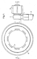
- Figure 1 is a frontal view of a preferred form of positive pressure demand valve in accordance with the invention;
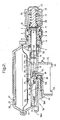
- Figure 2 is a section on the line II-II through the valve of Figure 1, shown in an open condition;
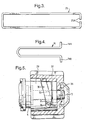
- Figure 3 is a plan view, to an enlarged scale, of the diaphragm lever used in the valve of Figures 1 and 2;
- Figure 4 is a plan view, to an enlarged scale, of a valve link used in the valve of Figures 1 and 2
- Figure 5 is a part sectional view, to an enlarged scale, of part of the bypass valve incorporated in the valve of Figures 1 and 2;
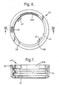
- Figure 6 is a frontal view of a mask socket for coupling with the valve of Figures 1 and 2; and
- Figure 7 is a section on the line VII-VII through the socket of Figure 6.
-
- With reference to the drawings, the illustrated valve is for regulating the flow from a source of compressed air (not shown) into a facemask (not shown) worn by the user, at a variable rate sufficient to meet the breathing demand of the user and so as normally to maintain a specified super-ambient pressure within the facemask throughout the respiratory cycle. In use, a flexible hose H (Figure 1) from the air source is connected to the inlet spigot 1 of a
swivel connector 2 which leads, through radial ports 3 (Figure 2), into achamber 4 within abody member 5. A "balanced piston"valve member 6, in the form of a thin-walled tube of e.g. stainless steel, is borne slidably by thebody member 5 and sealed thereagainst by a low friction (e.g. energised PTFE)seal 7. One end of thevalve member 6 extends into thechamber 4 and there faces afixed valve seat 8. In the illustrated embodiment there is aport 9 through the centre of theseat 8 andfurther ports 10 around its periphery, but in normal operation flow between these ports is prevented by aseal 11 carried by the head of apiston 13 the purpose of which will be described hereinafter. - The opposite end of the
valve member 6 communicates with adiaphragm chamber 14 and with theoutlet 15 of the valve which in use is coupled into the inlet of the user's facemask. That end of the valve member is also mechanically coupled, through a two-armed wire link 16 and a flat, hook-shaped link 17, to one end of a coiledtension spring 18, the other end of which is anchored to afixed post 19. The assembly ofspring 18 andlinks chamber 14 and coaxial with thevalve member 6, the action of the spring being to bias the valve member in the direction away from itsseat 8. In the illustrated unseated condition of the valve member, a flowpath will therefore be formed fromchamber 4, through the interior of thevalve member 6, intochamber 14 and out through theoutlet 15, the rate of flow at any time being determined by the spacing of the end of the valve member from itsseat 8 and of course being shut off in the event that the valve member is moved into contact with the seat. - Bounding the side of
chamber 14 opposite to theoutlet 15 is a flexible diaphragm 20 of e.g. silicone rubber.
This diaphragm is clamped peripherally betweenhousing members rigid plate 23. Theplate 23 carries abridge piece 24 by which is trapped one end of a two-armed wire lever 25. The opposite ends of the lever's arms are turned in (as shown at 25A in Figure 3)and pivoted where indicated at 26 in thehousing member 21, with the lever straddling thevalve member 6. The ends of the two arms of thewire link 16 are turned out (as shown at 16A in Figure 4) to pass throughslots 6A in the wall of the valve member and abut the straddling arms of the lever 25. The action of thespring 18 in withdrawing the valve member from itsseat 8 is therefore also to pivot the lever 25 anticlockwise (as viewed in Figure 2) and bias the diaphragm 20 inwards with respect to thechamber 14. - It will be appreciated that in use of the illustrated valve the inner side of the diaphragm 20 is exposed to the air pressure within chamber 14 (which is substantially the same as in the user's facemask) while the outer side of the diaphragm is exposed to ambient pressure (for which purpose the
housing member 22 is ventilated with a ring of slots 27). The diaphragm will accordingly flex inwardly and outwardly in accordance with variations in the pressure differential across it. That is say, a reduction in the pressure withinchamber 14 consequent upon inhalation of the user will draw the diaphragm 20 inwards allowing thevalve member 6 to open (or open further) under the bias ofspring 18 and supply air to the user in accordance with his breathing demand. Conversely, at the end of inhalation and during exhalation the pressure withinchamber 14 will rise, therefore flexing the diaphragm 20 outwardly and pivoting the lever 25 clockwise (as viewed in Figure 2) so that the valve member is pushed towards itsseat 8 and reduces the rate of flow through the valve (or eventually shuts off). At all times, however, the system is biased towards an open position by thespring 18 to ensure that a specified minimum super-ambient pressure is maintained within thechamber 14 and facemask throughout the entire breathing cycle, thereby ensuring that any leakage between the facemask and the external atmosphere can only be in the outward direction. - As usual, the facemask will be equipped with a separate one-way exhalation valve (set at a higher opening pressure than the closing pressure of the demand valve) through which the user's exhalate is vented and which ensures that a fresh supply of air is provided by the demand valve to the user upon each inhalation.
- Advantages of the "balanced piston" valve arrangement described herein are that only small forces are required in order to open and close the
valve member 6 and that it can operate consistently despite variations in the supply pressure. In particular when the valve is closed there is no force imparted by the supply pressure inchamber 4 acting to open it. Biasing of the system is accomplished by thesingle spring 18 in contrast to the conventional practice with "positive pressure" demand valves where there is one spring applied to the valve member in the closing direction (to counter the force of the supply pressure) plus a separate biasing spring applied to the diaphragm in the valve-opening direction. - Further features of the illustrated valve will now be described.
- Firstly, it is desirable that the user of a demand valve has the option of bypassing the operation of the usual automatic control means in the event of some failure in the latter which results in an insufficient rate of flow being supplied by the valve or of the valve member even becoming stuck in its closed position. It is also desirable, particularly in the case of the illustrated valve where the supply pressure has no tendency to unseat the
valve member 6, that means are provided for venting excess pressure in the event that an abnormally high supply pressure is experienced which might otherwise lead to a danger of bursting the supply hose H. In the illustrated valve the latter function is accomplished by thepiston 13 to which the supply pressure is communicated from thechamber 4 byports 10 around thevalve seat 8. Astrong spring 28 compressed between this piston and asleeve 29 on the end of thebody member 5 normally keeps the piston in its illustrated closed position against the "reverse" side cf theseat 8. If the supplied pressure force exceeds the spring force on thepiston 13, however, it will be displaced from theseat 8 and open a flow path from theports 10 around the reverse side of theseat 8 and through itscentral port 9, thereby venting the excess pressure through the main valve into the facemask (and thence to atmosphere through the exhalation valve or around the face seal). - The
same piston 13 can be displaced manually by the user to supply air continuously through theport 9, and thereby bypass the operation of thediaphragm 23, lever 25 andvalve member 6 if necessary. For this purpose, and with reference to Figure 5, thesleeve 29 is formed at two diametrically opposite positions withcam surfaces 30 each engageable with arespective peg 31 on thefixed body member 5. Aknob 32 is keyed to thesleeve 29 for turning the same and is formed internally withcam surfaces 33 facing thesurfaces 30 so as collectively to define a pair of helical slots. In the closed position of the bypass as illustrated in the Figures the rotational position of thesleeve 29 on thebody member 5 is defined bydetent recesses 34 adjacent to thecam surfaces 30 engaging thepegs 31, the sleeve being urged against thepegs 31 in this position by the action of thespring 28. A quarter anti-clockwise turn of theknob 32, however, causes thesleeve 29 to turn likewise with the helical slots defined betweenfaces 30/33 running over thepegs 31 so that the sleeve and knob are also displaced axially away from thebody member 5 by a distance determined by the pitch of those slots. In so doing theknob 32 engages aretainer 35 on the end of thepiston 13 to withdraw the piston from theseat 8 and open the bypass flowpath. - Another desirable feature of a positive pressure demand valve is a so-called "first breath" mechanism. To explain, it is frequently the case that the user of a breathing apparatus, after donning the apparatus, turning on the gas supply and checking the operation of the apparatus, has to stand by for a period before entering the hazardous zone in which respiratory protection is required. For personal comfort and to avoid unnecessary depletion of the gas source it is usual to doff the facemask during such periods, or disconnect the demand valve from the facemask and breath ambient air through the mask inlet. In either case, since the pressure sensed within the demand valve is now only ambient, its normal reaction is to open fully under its positive pressure bias (i.e.
spring 18 in the present example), which would lead to rapid depletion of the gas source if steps are not taken to shut off the flow. It is undesirable on such occasions to shut off the gas supply at source and so it is known to provide a demand valve itself with manually-operable means for closing the valve. It is also known to provide means for automatically releasing the closure of the valve when a specified sub-ambient pressure is applied to its outlet so that as soon as the facemask is donned once more, or the demand valve is reconnected, the first inhalation of the user will create the necessary negative pressure to release the valve and it will automatically revert to its normal positive pressure mode of operation. Such a "first breath" mechanism is incorporated in the illustrated demand valve and will now be described. - That is to say a
slide 36, manually-accessible at 36A, is borne in the side of thevalve outlet 15 and biased outwards by acompression spring 37. The inner end of tne slide 36 carries aflanged button 38 which faces thehead 17A of the hook-shapedplate 17 below its connection to thespring 18. Alight compression spring 39 is also trapped between thehead 17A of the plate and the end of thelink 16 coupled to that plate. The effect of pressing in theslide 36, therefore, is to push theplate 17 to the right (as viewed in Figure 2) and this has the effect of seating thevalve member 6, thereby shutting off the flow of gas through the valve. Furthermore as the hooked end 17B of theplate 17 encounters an aperture 40 in a baffle 41 extending across thechamber 14 the plate is allowed to pivot under the force applied to its head from theslide button 38 so that its hooked end enters the aperture 40 and retains the plate in its displaced position, while theslide 36 is free to return to its outward position under the action ofspring 37. Thevalve member 6 therefore remains seated under the force of thespring 39 while it is relieved of the force of themain biasing spring 18. Necessary lost-motion between theplate 17 and link 16 during this action is provided by theslot 17C in the plate. Subsequent generation of a negative pressure withinchamber 14 by inhalation of the user when the facemask is donned draws in the diaphragm 20 to its fullest extent so that thediaphragm plate 23 engages the hook 17B and presses it out of the aperture 40, thereby allowing thespring 18 to pull theplate 17 clear of the aperture 40 and resume its positive pressure control of the valve. - The
slide 36 also serves the function of locking the demand valve into the inlet of the user's facemask. Theoutlet 15 of the demand valve is formed as a bayonet connector, with a pair ofcircumferential ledges 42 projecting at two diametrically opposite locations. Thecorresponding inlet socket 43 of the facemask is shown in Figures 6 and 7. It is formed with aninternal groove 44 complementary to theledges 42, this groove being relieved to defineslots 45A, 45B at two opposite locations. The valve is coupled to the socket by passing theledges 42 axially through theslots 45A, 45B and giving the valve a quarter turn to locate theledges 42 in respective portions of thegroove 44. Respective pairs ofstops cam surface 48 which engages the exposed part 36B of theslide 36 to press in the slide as the valve is turned in the socket, the slide subsequently springing out into adetent slot 49 in the side of the socket to prevent return rotation of the valve when it has reached the fully inserted position. To remove the valve from the socket, however, theslide 36 is pressed in manually to free the valve for return rotation. - From the foregoing it will be appreciated that the "first breath" mechanism described above will be automatically set by operation of the
slide 36 whenever the demand valve is connected to our disconnected from thesocket 43. - Finally, the illustrated demand valve is also configured to alleviate a problem which can arise when operating at low temperatures. A demand valve may typically be required to operate in a range of ambient temperatures down to -30°C. When coupled with the cooling effect of the gas expansion as it passes the
valve member 6 this can lead to temperatures as low as -60° or -70°C within thechamber 14. At such low temperatures available diaphragm materials may stiffen to the extent that reliable operation of the valve cannot be maintained. Bearing in mind that flexure of the illustrated diaphragm 20 occurs only at its peripheral region it is the temperature of that region which is critical in this respect. As that region is also unreinforced by theplate 23 it is necessary to ensure that it cannot be damaged by any objects or material entering the valve housing through theventilation slots 27. In view of both of these factors the illustrated arrangement has been adopted in which theslots 27 in thehousing member 22 are located towards its periphery and anannular baffle 50 is formed on the inside ofmember 22 to protect the diaphragm 20 from contact through those slots and to deflect ambient air (which is effectively pumped in and out of thehousing member 22 as the diaphragm flexes with each breathing cycle) to pass over the peripheral region of the diaphragm. Even at an ambient temperature of -30°C this air may be sufficiently "warmer" than the expanding gas inside the valve to keep the periphery of the diaphragm sufficiently flexible.
Claims (9)
- A gas flow control valve comprising: an inlet chamber (4) and an outlet chamber (14,15);
a movable valve member (6) for controlling the flow of pressurised gas from the inlet chamber (4) to the outlet chamber (14,15); and
a flexible pressure-responsive member (20) sensitive to the gas pressure within the outlet chamber (14,15) for controlling the movement of the valve member (6);
the pressure-responsive member comprising a diaphragm (20) having a rigid central portion (23) and a flexible peripheral portion and being held by its periphery in the valve structure (21,22) such as to be exposed on one side to the gas pressure within said outlet chamber (14,15) and on the opposite side to ambient pressure;
the valve structure on said opposite side of the diaphragm being in the form of a housing (22) having a plurality of openings (27) spaced around the axis of the diaphragm (20) to provide communication between the external atmosphere and the interior of the housing (22); and
baffle means (50) being provided inside the housing (22) in association with said openings (27) to protect the diaphragm (20) from damage and to deflect incoming atmospheric air to flow over the peripheral portion thereof. - A gas flow control valve comprising: an inlet chamber (4) and an outlet chamber (14,15);
a movable valve member (6) for controlling the flow of pressurized gas from the inlet chamber (4) to the outlet chamber (14,15);
a flexible pressure-responsive member (20) sensitive to the gas pressure within the outlet chamber (14,15) for controlling the movement of the valve member (6)
whereby normally to maintain a specified super-ambient pressure within the outlet chamber (14,15);
a detent member (17) linked to the valve member (6) and a manually-operable control member (36) by which the detent member (17) can be actuated to a detent position in which position the valve member (6) is maintained closed but from which position the detent member (17) can be released by flexure of the pressure-responsive member (20) in response to a predetermined sub-ambient pressure within the outlet chamber (14,15);
a gas outlet portion (15) of the valve being configured as a tubular bayonet fitting;
in combination with a device having a gas inlet fitting (43) to receive said outlet portion (15); the valve having a spring-biased (37) retainer (36) borne radially in association with said bayonet fitting to retain that fitting in a specified rotary position with respect to said inlet fitting (43) when inserted therein; said retainer (36) also constituting said manually-operable control member (36). - The valve according to claim 1 or 2, comprising
a valve seat (8) facing the valve member (6) in the inlet chamber (4) such that the spacing of the valve member (6) from said seat (8) controls the rate of gas flow through the valve member (6) from the inlet chamber to the outlet chamber and contact of the valve member with said seat shuts off such flow, and
a spring means acting upon the valve member (6) to bias the same away from said seat (8). - The valve according to claim 3, wherein said spring means comprises a tension spring linked coaxially between said other end of the valve member and a fixed part of the valve structure.
- The valve according to claim 3 or 4, wherein said spring means constitutes the sole spring means acting upon said valve member, pressure-responsive member or mechanical linkage means, in normal operation of the valve.
- The valve according to claim 5, wherein said flexible diaphragm of the pressure-responsive member (20) bounds a portion of the outlet chamber and is adapted to flex inwardly and outwardly of said chamber in response to reduction and increase of gas pressure within said chamber respectively; and
said mechanical linkage means comprises a lever linked at one end to said diaphragm, pivoted at the other end to a fixed part of the valve structure, and linked at an intermediate position to the valve member,
whereby to push the valve member towards said seat in response to outward flexure of said diaphragm. - The valve according to according to claim 3, further including bypass valve means comprising: a bypass chamber on the opposite side of said valve seat to the main valve member;
at least one inlet port opening from the inlet chamber to said bypass chamber; an outlet port opening from said bypass chamber through said valve seat at a position to communicate with the interior of the main valve member while the latter is seated; and
a bypass valve member in said bypass chamber which normally isolates said outlet port from said inlet port but which can be displaced to permit gas to flow from the inlet chamber to the interior of the main valve member via said bypass chamber. - The valve according to claim 7 comprising manually-operable control means for displacing said bypass valve member.
- The valve according to claim 7 wherein said bypass valve member is in the form of a spring-biased piston which is adapted to be displaced by gas pressure communicated through said inlet port if an abnormally high pressure pertains in the inlet chamber while the main valve member is seated.
Applications Claiming Priority (4)
| Application Number | Priority Date | Filing Date | Title |
|---|---|---|---|
| GB939319580A GB9319580D0 (en) | 1993-09-22 | 1993-09-22 | Valves |
| GB9319580 | 1993-09-22 | ||
| EP94306766A EP0645163B1 (en) | 1993-09-22 | 1994-09-15 | Valve for breathing apparatus |
| EP98117278A EP0884069B1 (en) | 1993-09-22 | 1994-09-15 | Valve for breathing apparatus |
Related Parent Applications (1)
| Application Number | Title | Priority Date | Filing Date |
|---|---|---|---|
| EP98117278A Division EP0884069B1 (en) | 1993-09-22 | 1994-09-15 | Valve for breathing apparatus |
Publications (1)
| Publication Number | Publication Date |
|---|---|
| EP1506794A2 true EP1506794A2 (en) | 2005-02-16 |
Family
ID=10742365
Family Applications (4)
| Application Number | Title | Priority Date | Filing Date |
|---|---|---|---|
| EP94306766A Expired - Lifetime EP0645163B1 (en) | 1993-09-22 | 1994-09-15 | Valve for breathing apparatus |
| EP04026737A Withdrawn EP1506794A2 (en) | 1993-09-22 | 1994-09-15 | Valve |
| EP98117277A Expired - Lifetime EP0885631B1 (en) | 1993-09-22 | 1994-09-15 | Valve for breathing apparatus |
| EP98117278A Expired - Lifetime EP0884069B1 (en) | 1993-09-22 | 1994-09-15 | Valve for breathing apparatus |
Family Applications Before (1)
| Application Number | Title | Priority Date | Filing Date |
|---|---|---|---|
| EP94306766A Expired - Lifetime EP0645163B1 (en) | 1993-09-22 | 1994-09-15 | Valve for breathing apparatus |
Family Applications After (2)
| Application Number | Title | Priority Date | Filing Date |
|---|---|---|---|
| EP98117277A Expired - Lifetime EP0885631B1 (en) | 1993-09-22 | 1994-09-15 | Valve for breathing apparatus |
| EP98117278A Expired - Lifetime EP0884069B1 (en) | 1993-09-22 | 1994-09-15 | Valve for breathing apparatus |
Country Status (5)
| Country | Link |
|---|---|
| US (1) | US5501213A (en) |
| EP (4) | EP0645163B1 (en) |
| AU (1) | AU676365B2 (en) |
| DE (3) | DE69432873T2 (en) |
| GB (2) | GB9319580D0 (en) |
Families Citing this family (29)
| Publication number | Priority date | Publication date | Assignee | Title |
|---|---|---|---|---|
| GB9608336D0 (en) * | 1996-04-23 | 1996-06-26 | Draeger Ltd | Gas cylinder connection |
| IT241613Y1 (en) * | 1996-10-23 | 2001-05-09 | Htm Sport Spa | DISPENSER FOR UNDERWATER RESPIRATORY APPLIANCES. |
| WO2002032757A1 (en) * | 1999-09-24 | 2002-04-25 | Tabata Co., Ltd. | Regulator for diving |
| WO2002047972A1 (en) * | 2000-12-13 | 2002-06-20 | Olivier Isler | Ergonomic diver's helmet in two separable parts with mouthpiece change system |
| GB0112958D0 (en) * | 2001-05-29 | 2001-07-18 | F X K Patents Ltd | A pressure regulator |
| US20040035415A1 (en) * | 2002-08-22 | 2004-02-26 | Michel Faligant | Breathing apparatus |
| GB2402458B (en) * | 2003-06-06 | 2006-04-19 | Internat Safety Instr Inc | Demand valves for breathing apparatus |
| DE102005058401B3 (en) * | 2005-12-07 | 2007-08-02 | Egon Knoch | Automatic lung regulator for compressed air respiration device, has base housing and diaphragm, which is controlled by human breathing, where rocker arm has control mechanics for regulating breathing air supply to respirator mask |
| WO2008101302A1 (en) * | 2007-02-23 | 2008-08-28 | Resmed Ltd | Demand valve for breathing apparatus |
| KR100903409B1 (en) | 2007-11-23 | 2009-06-18 | 주식회사 산청 | A supply valve assembly for a breathing apparatus |
| US8336547B1 (en) | 2012-01-20 | 2012-12-25 | Amron International, Inc. | Breathing mask |
| ITGE20120027A1 (en) * | 2012-03-06 | 2013-09-07 | Mares Spa | SECOND STAGE OF PRESSURE REDUCTION FOR UNDERWATER USE PROVIDED WITH A BYPASS DUCT AND MEANS OF ADJUSTMENT OF THE GAS FLOW IN ENTRY OR OF THE PASSING FLOW TO THE INSIDE OF THAT BYPASS |
| US11052268B2 (en) | 2013-02-01 | 2021-07-06 | 3M Innovative Properties Company | Respirator negative pressure fit check devices and methods |
| US9517367B2 (en) | 2013-02-01 | 2016-12-13 | 3M Innovative Properties Company | Respiratory mask having a clean air inlet chamber |
| US9950202B2 (en) | 2013-02-01 | 2018-04-24 | 3M Innovative Properties Company | Respirator negative pressure fit check devices and methods |
| USD732642S1 (en) * | 2014-01-23 | 2015-06-23 | Kirby Morgan Dive Systems, Inc. | Diving regulator |
| CN103949018B (en) * | 2014-03-28 | 2016-09-14 | 党新洲 | A kind of mask and respiratory organ |
| CA3009824C (en) * | 2015-12-30 | 2023-12-05 | Scott Technologies, Inc. | Respirator mask with air-saver switch |
| KR102450400B1 (en) | 2016-03-28 | 2022-10-04 | 쓰리엠 이노베이티브 프로퍼티즈 캄파니 | Respiratory compatibility test sealing device and method |
| USD827810S1 (en) | 2016-03-28 | 2018-09-04 | 3M Innovative Properties Company | Hardhat suspension adapter for half facepiece respirators |
| KR102420496B1 (en) | 2016-03-28 | 2022-07-13 | 쓰리엠 이노베이티브 프로퍼티즈 캄파니 | Multi-chamber respiratory seal device and method |
| CN108883321A (en) | 2016-03-28 | 2018-11-23 | 3M创新有限公司 | Headgear Suspension Attachment Elements |
| USD816209S1 (en) | 2016-03-28 | 2018-04-24 | 3M Innovative Properties Company | Respirator inlet port connection seal |
| USD842982S1 (en) | 2016-03-28 | 2019-03-12 | 3M Innovative Properties Company | Hardhat suspension adapter for half facepiece respirators |
| PL229940B1 (en) * | 2017-04-11 | 2018-09-28 | Xdeep Spolka Z Ograniczona Odpowiedzialnoscia | Second stage of diving automaton |
| CN107096142A (en) * | 2017-06-22 | 2017-08-29 | 东台市江海救生消防设备有限公司 | Positive-pressure air respirator |
| GB2575072B (en) * | 2018-06-27 | 2022-06-15 | Draeger Safety Uk Ltd | Demand regulator |
| DE102020000335A1 (en) * | 2020-01-21 | 2021-07-22 | Drägerwerk AG & Co. KGaA | Valve arrangement with shut-off unit and procedure for a ventilator |
| CN112691269B (en) * | 2020-12-30 | 2025-11-18 | 北京瑞迈特医疗科技股份有限公司 | Fluid flow control components and parts, housings and devices, ventilation therapy equipment and oxygen supply control methods |
Citations (1)
| Publication number | Priority date | Publication date | Assignee | Title |
|---|---|---|---|---|
| US3647175A (en) | 1969-03-18 | 1972-03-07 | Andre Bonneau | Fluid flow control valve |
Family Cites Families (25)
| Publication number | Priority date | Publication date | Assignee | Title |
|---|---|---|---|---|
| DE389412C (en) * | 1920-10-17 | 1924-01-31 | Gafag Gasfeuerungs Ges | Method for gasifying uncomfortable fuels in the generator using a clumping agent |
| CH389412A (en) * | 1960-02-18 | 1965-03-15 | Aga Ab | Respiratory device |
| GB1367286A (en) * | 1971-11-01 | 1974-09-18 | Draeger Normalair Ltd | Fluid flow valve arrangements |
| GB1569875A (en) * | 1975-10-08 | 1980-06-25 | Submarine & Safety Eng Ltd | Pressure control valve |
| GB1570065A (en) * | 1976-10-21 | 1980-06-25 | Draeger Safety Ltd | Breathing apparatus |
| CA1120372A (en) * | 1978-02-13 | 1982-03-23 | Max Isaacson | Demand inhalation valve system |
| IT1104244B (en) * | 1978-05-16 | 1985-10-21 | Amf Mares Sub Spa | PRESSURE REDUCER FOR SELF-BREATHING EQUIPMENT IN PARTICULAR FOR SELF-BREATHING UNDERWATER EQUIPMENT |
| US4345593A (en) * | 1978-07-19 | 1982-08-24 | A-T-O Inc. | Pressure-demand breathing apparatus with automatic air shut-off |
| DE2965808D1 (en) * | 1978-12-13 | 1983-08-04 | Siebe Gorman & Co Ltd | Valve assembly and breathing apparatus incorporating this valve assembly |
| US4224938A (en) * | 1979-01-29 | 1980-09-30 | American Underwater Products | Balanced second stage for a two stage demand regulator |
| GB2054207B (en) * | 1979-06-21 | 1983-08-17 | Chubb Panorama | Valves and breathing apparatus incorporating such valves |
| SE428760B (en) * | 1979-10-09 | 1983-07-25 | Aga Ab | Breathing mask |
| DE3015760C2 (en) * | 1980-04-24 | 1982-03-25 | Drägerwerk AG, 2400 Lübeck | Lung-controlled compressed gas breathing apparatus with positive pressure in the breathing mask |
| US4345592A (en) * | 1980-09-10 | 1982-08-24 | A-T-O Inc. | Pressure demand regulator with automatic shut-off |
| GB2085306B (en) * | 1980-10-17 | 1984-09-12 | Sabre Safety Ltd | Breathing apparatus |
| GB2116852B (en) * | 1982-03-20 | 1985-05-30 | Chubb Panorama | Gas flow control valves |
| FR2511252A1 (en) * | 1982-04-02 | 1983-02-18 | Fenzy Sa | TIP FOR RESPIRATORY APPARATUS FOR CONNECTING THE MASK TO A BOTTLE OF RESPIRATORY GAS |
| DE3245717C1 (en) * | 1982-12-10 | 1984-06-07 | Drägerwerk AG, 2400 Lübeck | Lung-controlled valve for overpressure operation in the mask interior |
| DE3422023C2 (en) * | 1984-06-14 | 1987-04-23 | Drägerwerk AG, 2400 Lübeck | Lung regulator for breathing apparatus |
| DE3508130A1 (en) * | 1985-03-07 | 1986-09-11 | Drägerwerk AG, 2400 Lübeck | LUNG-CONTROLLED VALVE FOR RESPIRATORY MASKS WITH OVERPRESSURE IN THE MASK INTERIOR |
| GB2178964B (en) * | 1985-08-08 | 1989-02-01 | Sabre Safety Ltd | Positive pressure demand valves |
| DE3539668A1 (en) * | 1985-11-08 | 1987-05-21 | Draegerwerk Ag | Lung controlled diaphragm valve for respirator masks |
| GB2190001B (en) * | 1986-05-07 | 1990-08-08 | Peter Joseph Jackson | Pressure regulator |
| GB8621516D0 (en) * | 1986-09-06 | 1986-10-15 | Jackson P J | Pilot operated valves |
| IT224295Z2 (en) * | 1991-03-08 | 1996-03-14 | Scubapro Europ | VALVE, IN PARTICULAR FOR DIVING SCUBA BREATHERS. |
-
1993
- 1993-09-22 GB GB939319580A patent/GB9319580D0/en active Pending
-
1994
- 1994-09-15 EP EP94306766A patent/EP0645163B1/en not_active Expired - Lifetime
- 1994-09-15 DE DE69432873T patent/DE69432873T2/en not_active Expired - Fee Related
- 1994-09-15 EP EP04026737A patent/EP1506794A2/en not_active Withdrawn
- 1994-09-15 EP EP98117277A patent/EP0885631B1/en not_active Expired - Lifetime
- 1994-09-15 EP EP98117278A patent/EP0884069B1/en not_active Expired - Lifetime
- 1994-09-15 DE DE69418124T patent/DE69418124T2/en not_active Expired - Fee Related
- 1994-09-15 DE DE69434154T patent/DE69434154T2/en not_active Expired - Fee Related
- 1994-09-16 GB GB9418728A patent/GB2282213B/en not_active Expired - Fee Related
- 1994-09-20 US US08/309,992 patent/US5501213A/en not_active Expired - Lifetime
- 1994-09-22 AU AU74165/94A patent/AU676365B2/en not_active Ceased
Patent Citations (1)
| Publication number | Priority date | Publication date | Assignee | Title |
|---|---|---|---|---|
| US3647175A (en) | 1969-03-18 | 1972-03-07 | Andre Bonneau | Fluid flow control valve |
Also Published As
| Publication number | Publication date |
|---|---|
| DE69418124T2 (en) | 1999-12-16 |
| GB2282213B (en) | 1998-01-21 |
| EP0885631A2 (en) | 1998-12-23 |
| EP0885631B1 (en) | 2003-06-25 |
| US5501213A (en) | 1996-03-26 |
| DE69434154T2 (en) | 2005-11-24 |
| DE69432873T2 (en) | 2004-05-19 |
| EP0645163A1 (en) | 1995-03-29 |
| GB9319580D0 (en) | 1993-11-10 |
| EP0645163B1 (en) | 1999-04-28 |
| AU676365B2 (en) | 1997-03-06 |
| EP0884069A3 (en) | 2000-03-29 |
| GB2282213A (en) | 1995-03-29 |
| DE69418124D1 (en) | 1999-06-02 |
| EP0884069B1 (en) | 2004-11-24 |
| EP0885631A3 (en) | 2000-03-29 |
| DE69434154D1 (en) | 2004-12-30 |
| DE69432873D1 (en) | 2003-07-31 |
| GB9418728D0 (en) | 1994-11-02 |
| AU7416594A (en) | 1995-04-06 |
| EP0884069A2 (en) | 1998-12-16 |
Similar Documents
| Publication | Publication Date | Title |
|---|---|---|
| EP0645163B1 (en) | Valve for breathing apparatus | |
| US8733344B2 (en) | Mouthpiece supply valve control system | |
| US6016802A (en) | Breathing apparatus and facepiece therefor | |
| US4606340A (en) | Combined pressure compensating exhalation and anti-suffocation valve | |
| CA2255040C (en) | Breathing apparatus | |
| EP0401307B1 (en) | Crew oxygen mask with pneumatic comfort adjustment | |
| US4693242A (en) | Coupling connectors for respirator masks | |
| EP1262402A2 (en) | A pressure regulator | |
| US7111625B2 (en) | Demand valves for breathing apparatus | |
| US4850345A (en) | Pilot operated valves | |
| GB2315116A (en) | Gas flow control valves | |
| US4667670A (en) | Gas flow control valves | |
| US4178961A (en) | Lung-controlled membrane valve for compressed gas respirators | |
| EP3813955B1 (en) | Demand regulator | |
| AU2010247145B2 (en) | Mask for breathing apparatus | |
| GB2116852A (en) | Gas flow control valves | |
| GB2195900A (en) | Pilot operated valve for breathing apparatus | |
| JPH078568A (en) | Air respirator | |
| GB2234368A (en) | Valves | |
| US20050189019A1 (en) | Second exhaust valve for a second stage regulator |
Legal Events
| Date | Code | Title | Description |
|---|---|---|---|
| PUAI | Public reference made under article 153(3) epc to a published international application that has entered the european phase |
Free format text: ORIGINAL CODE: 0009012 |
|
| AC | Divisional application: reference to earlier application |
Ref document number: 0884069 Country of ref document: EP Kind code of ref document: P Ref document number: 0645163 Country of ref document: EP Kind code of ref document: P |
|
| AK | Designated contracting states |
Kind code of ref document: A2 Designated state(s): DE FR SE |
|
| STAA | Information on the status of an ep patent application or granted ep patent |
Free format text: STATUS: THE APPLICATION HAS BEEN WITHDRAWN |
|
| 18W | Application withdrawn |
Effective date: 20050902 |