EP1506819A2 - Dispositif de traitement de la surface de pièces, en particulier de carrosserie de vehicule - Google Patents
Dispositif de traitement de la surface de pièces, en particulier de carrosserie de vehicule Download PDFInfo
- Publication number
- EP1506819A2 EP1506819A2 EP04018226A EP04018226A EP1506819A2 EP 1506819 A2 EP1506819 A2 EP 1506819A2 EP 04018226 A EP04018226 A EP 04018226A EP 04018226 A EP04018226 A EP 04018226A EP 1506819 A2 EP1506819 A2 EP 1506819A2
- Authority
- EP
- European Patent Office
- Prior art keywords
- tool
- portal
- workpiece
- axis
- carriage
- Prior art date
- Legal status (The legal status is an assumption and is not a legal conclusion. Google has not performed a legal analysis and makes no representation as to the accuracy of the status listed.)
- Withdrawn
Links
Images


Classifications
-
- B—PERFORMING OPERATIONS; TRANSPORTING
- B05—SPRAYING OR ATOMISING IN GENERAL; APPLYING FLUENT MATERIALS TO SURFACES, IN GENERAL
- B05B—SPRAYING APPARATUS; ATOMISING APPARATUS; NOZZLES
- B05B13/00—Machines or plants for applying liquids or other fluent materials to surfaces of objects or other work by spraying, not covered by groups B05B1/00 - B05B11/00
- B05B13/02—Means for supporting work; Arrangement or mounting of spray heads; Adaptation or arrangement of means for feeding work
- B05B13/04—Means for supporting work; Arrangement or mounting of spray heads; Adaptation or arrangement of means for feeding work the spray heads being moved during spraying operation
- B05B13/0447—Installation or apparatus for applying liquid or other fluent material to conveyed separate articles
- B05B13/0452—Installation or apparatus for applying liquid or other fluent material to conveyed separate articles the objects being vehicle components, e.g. vehicle bodies
-
- B—PERFORMING OPERATIONS; TRANSPORTING
- B05—SPRAYING OR ATOMISING IN GENERAL; APPLYING FLUENT MATERIALS TO SURFACES, IN GENERAL
- B05B—SPRAYING APPARATUS; ATOMISING APPARATUS; NOZZLES
- B05B13/00—Machines or plants for applying liquids or other fluent materials to surfaces of objects or other work by spraying, not covered by groups B05B1/00 - B05B11/00
- B05B13/02—Means for supporting work; Arrangement or mounting of spray heads; Adaptation or arrangement of means for feeding work
- B05B13/04—Means for supporting work; Arrangement or mounting of spray heads; Adaptation or arrangement of means for feeding work the spray heads being moved during spraying operation
- B05B13/0431—Means for supporting work; Arrangement or mounting of spray heads; Adaptation or arrangement of means for feeding work the spray heads being moved during spraying operation with spray heads moved by robots or articulated arms, e.g. for applying liquid or other fluent material to three-dimensional [3D] surfaces
- B05B13/0433—Means for supporting work; Arrangement or mounting of spray heads; Adaptation or arrangement of means for feeding work the spray heads being moved during spraying operation with spray heads moved by robots or articulated arms, e.g. for applying liquid or other fluent material to three-dimensional [3D] surfaces the work being vehicle components, e.g. vehicle bodies
-
- B—PERFORMING OPERATIONS; TRANSPORTING
- B25—HAND TOOLS; PORTABLE POWER-DRIVEN TOOLS; MANIPULATORS
- B25J—MANIPULATORS; CHAMBERS PROVIDED WITH MANIPULATION DEVICES
- B25J18/00—Arms
- B25J18/005—Arms having a curved shape
-
- B—PERFORMING OPERATIONS; TRANSPORTING
- B05—SPRAYING OR ATOMISING IN GENERAL; APPLYING FLUENT MATERIALS TO SURFACES, IN GENERAL
- B05B—SPRAYING APPARATUS; ATOMISING APPARATUS; NOZZLES
- B05B13/00—Machines or plants for applying liquids or other fluent materials to surfaces of objects or other work by spraying, not covered by groups B05B1/00 - B05B11/00
- B05B13/02—Means for supporting work; Arrangement or mounting of spray heads; Adaptation or arrangement of means for feeding work
- B05B13/04—Means for supporting work; Arrangement or mounting of spray heads; Adaptation or arrangement of means for feeding work the spray heads being moved during spraying operation
- B05B13/0431—Means for supporting work; Arrangement or mounting of spray heads; Adaptation or arrangement of means for feeding work the spray heads being moved during spraying operation with spray heads moved by robots or articulated arms, e.g. for applying liquid or other fluent material to three-dimensional [3D] surfaces
Definitions
- the object of the present invention is a device of the type mentioned above, at which is a very fast, with high dynamics and precision Successful movement of the surface treatment performing tool is possible.
- Centerpiece of the present invention is the stand-like Portal, in the passage opening the workpiece is positioned at the surface treatment.
- the movable on the guide rail of the portal Carriage which carries the tool over the holding arm
- the device which is a relative movement between tool and workpiece in the direction of the axis of Through hole allows the tool can be in a "raw position" at the beginning of the machining process bring from the tool then at the actual Surface treatment on a short way all to be worked Surface areas reached. Only in exceptional cases is during the surface treatment itself a method of Sleigh along the portal or one over the own Range of the holding arm beyond reaching relative movement between workpiece and tool in the axial direction of Through opening required.
- the holding arm can open this way be built relatively short.
- the at the movement of the holding arm to be accelerated masses are relatively low, so that high speeds and high accelerations and delays attainable are.
- the relatively short length of the holding arm ensures a high degree of precision Motion control.
- the guide rail on which of the support arm carrying carriage movable is, the workpiece only along an arc or enclose completely annular.
- the orientation, under which the tool touches the surface of the workpiece is not indifferent, has the tool supporting arm support those degrees of freedom that are not just the guidance of the tool along a certain Line but also the setting of a desired orientation of the tool at each point of its path of movement enable.
- the holding arm may be a multi-unit robotic arm. Such robot arms and their control are commercial available.
- the device for generating the relative movement can be designed so that they move the portal in total can.
- the "raw position" of the tool in the direction the axis of the passage opening of the portal is So brought about by the fact that the entire portal accordingly is adjusted.
- the device for generating the relative movement can also be designed so that they face the workpiece can move the portal. Again, the procedure is of the workpiece relative to the portal usually only the induction of the starting position of the tool is used.
- the device for generating the relative movement is in another embodiment of the invention designed so that they move the tool in the direction of Adjust the axis of the passage opening of the portal can.
- This embodiment has the advantage that those Parts which are parallel to the axis of the passage opening to be adjusted, namely the holding arm and the Tool itself, are relatively lightweight and therefore the Means with which generates the axis-parallel motion is, can be kept relatively simple.
- the holding arm designed in this way essentially corresponds a four-axis, conventional robotic arm, wherein the mobility of the support arm carrying carriage along the guide rail as the fifth degree of freedom of movement ("fifth axis").
- the term "azimuth” means a direction that is essentially in is a level parallel to the portal level and is substantially perpendicular to that direction, in which the tool is adjusted to the workpiece becomes. In a circular arc-shaped leadership of the portal Thus, the azimuthal direction is perpendicular to the radial direction.
- the mobility and range of the holding arm are at that embodiment of the invention in addition increases, wherein the first member of the slide indirectly is attached via a turntable, which is around a to the axis of the passage opening substantially parallel Axle is rotatable.
- the pivot axes of the first two links of the support arm only in a certain position of the fifth wheel azimuthally aligned. You wander at a twist of the Turntable from this position from the azimuthal Alignment out, but staying in one go to the plane of the portal parallel plane.
- the device for generating the relative movement can alternatively, a parallel to the axis of the through hole comprising motorized slide, the on the slide which can be moved on the guide rail is attached and attached to the support arm. So here is the axis of the passage opening of the Portals parallel relative movement between the workpiece and the tool by an axial movement of the holding arm and thus the tool holding the second carriage brought about.
- the portal can be attached to opposite end faces respectively to carry a guide rail on which at least a support arm carrying a carriage movable is. In this way, can be at one and the same Portal several sledges and thus attach tools which are independently movable. hereby the capacity of the device is increased overall; large workpieces can be processed faster.
- the guide rail curved in a circular or circular arc it suffices if the guide rail curved in a circular or circular arc to all Surface areas of the workpiece substantially equally easy to reach.
- the workpiece it is also possible for the workpiece to be shaped Shape of the guide rail surrounding the workpiece to adjust the contour of the workpiece.
- the guide rail along the whole or a part the circumference of a rounded polygon, e.g. B. one Rectangle, a triangle or the like runs.
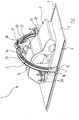
- the illustrated in the drawing and a total of The device designated by reference numeral 1 is used in addition, on car bodies 2 adhesive or sealant caterpillars to raise, more or less complicated, closed or not closed lines on outer or inner surface areas of the respective vehicle body 2 follow.
- the device 1 has a portal 3 with a through hole 50, which in the Through opening 50 positioned vehicle body. 2 bridged and thereby approximately constant distance from this has.
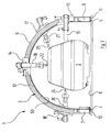
- the portal 3 is along two rails 4, 5, which are parallel on both sides of the vehicle body. 2 extend on the floor space 6, motorized. It comprises two relatively short vertical columns 7, 8, which at their upper ends by a semicircular Support structure 9 are connected. The columns 7, 8 are at their lower ends with trolleys 10, 11th provided, which are shown only schematically in the drawing are and the procedure of the portal 3 on the Allow rails 4 and 5.
- Both on the front and on the rear end the semicircular support structure 9 is respectively a likewise semicircular guide rail 12 and 13 attached.
- On each of these guide rails 12, 13 are each two carriages 14, 15, 16, 17 movable, each serving as a holding arm robot arm 18, 19, 20, 21 wear.
- Each of these robot arms 18, 19, 20, 21 holds at its free end an adhesive or sealant gun 22, 23, 24, 25.
- the following is the simplicity just a glue gun spoken.
- the robot arm 18 comprises a total of four members: a first Member 18a, which is bent in a quarter circle, is articulated at its one end with a turntable 51 connected, in turn, about an axis parallel to the axis of the through hole 50 extends, rotatable is attached to the carriage 14. This rotational movement happens with the help of a not recognizable in the drawing Engine.
- the pivotal movement of the first member 18a opposite the fifth wheel 51 is by means of a motor 26 accomplished.
- the pivot axis extends in a plane parallel to the spanned by the portal 3 Level is, and is at the in the drawing shown position of the fifth wheel 51 substantially perpendicular to the radial direction relative to the semicircular Support structure 9. This direction is here "azimuthal" called. At a rotation of the fifth wheel 51 from this position leaves the pivot axis the azimuthal Alignment, however, remains in a plane that leads to the Essentially spanned by the portal 3 level is parallel.
- a second member 18b is at the second end portion hinged to the first member 18a. This pivoting movement takes place under the action of a motor 27.
- the corresponding Swivel axis is parallel to the first between the first member 18a and the fifth wheel 51 effective Pivot axis.
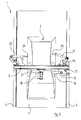
- the third member 18 c of the robot arm 18 the second member 18b continues coaxially and is around common axis rotatable by motor.
- the corresponding Engine is not visible in the drawing.
- On the outside End of the third link 18c is a fourth link 18d hinged, which pivots by means of a motor 28 can be.
- the corresponding pivot axis runs perpendicular to the axis of the links 18b and 18c.
- the fourth Member 18d carries at its free end the spray gun 22nd
- each robot arm 18 to 21 of the device 1 thus have six Degrees of freedom, in the language of robotics six "Axes".
- One degree of freedom, that of movement the respective carriage 14 to 17 along the corresponding Guide rail 12, 13 corresponds, three Pivoting and two turning degrees of freedom.
- each robot arm 18 to 23 within a certain area with the tip of the glue gun 22 to 25 a preprogrammed line on the Surface of the vehicle body 2 nachinate and doing
- a desired orientation of the Glue gun 22c to 25 opposite the surface of the Vehicle body 2 maintains.
- the vehicle body 2 can be achieved. This extends, as can be seen in particular from FIG is, the holding arm 19 through a window of the vehicle body in their interior, around there an adhesive bead applied.
- the device 1 described above operates as follows:
- the vehicle body 2 is using a in the Drawing transport system not shown below the support structure 9 in the passage opening 50 of the portal 3 brought and roughly positioned there. Now proceed The portal 3 so that as many as possible with adhesive to be provided lines on the vehicle body 2 in Area of robot arms 18 to 21 are located. With the help of Carriages 14 to 17 become the robot arms 18 to 21 along the guide rails 12, 13 positioned so that they all because of their six degrees of freedom of movement Areas of their assigned glue lines reachable. The glue guns 22 to 25 are now in function and with the help of the robot arms 18 to 21 guided along the respective glue line.
- the guide rails are not just the ones Form semicircular arches, but enclose that too machined workpiece ring-like from all sides.
- the shape of the guide rails can vary depending on the workpiece Diverge from circular or circular arc shape. It can For example, straight sections between curved Sections of the guide rails are inserted and so on polygon-like, e.g. approximately rectangular or triangular Forms of guide rails are used when As a result, the approximately constant distance between the Guide rails and the workpiece to be machined better can be complied with.
Landscapes
- Engineering & Computer Science (AREA)
- Robotics (AREA)
- Mechanical Engineering (AREA)
- Manipulator (AREA)
- Spray Control Apparatus (AREA)
Applications Claiming Priority (2)
| Application Number | Priority Date | Filing Date | Title |
|---|---|---|---|
| DE10337803 | 2003-08-14 | ||
| DE10337803A DE10337803A1 (de) | 2003-08-14 | 2003-08-14 | Vorrichtung zum Behandeln der Oberfläche von Werkstücken, insbesondere von Fahrzeugkarosserien |
Publications (2)
| Publication Number | Publication Date |
|---|---|
| EP1506819A2 true EP1506819A2 (fr) | 2005-02-16 |
| EP1506819A3 EP1506819A3 (fr) | 2007-12-26 |
Family
ID=33560343
Family Applications (1)
| Application Number | Title | Priority Date | Filing Date |
|---|---|---|---|
| EP04018226A Withdrawn EP1506819A3 (fr) | 2003-08-14 | 2004-08-02 | Dispositif de traitement de la surface de pièces, en particulier de carrosserie de vehicule |
Country Status (4)
| Country | Link |
|---|---|
| US (1) | US20050066890A1 (fr) |
| EP (1) | EP1506819A3 (fr) |
| CN (1) | CN1579716A (fr) |
| DE (1) | DE10337803A1 (fr) |
Cited By (10)
| Publication number | Priority date | Publication date | Assignee | Title |
|---|---|---|---|---|
| WO2005046880A3 (fr) * | 2003-11-06 | 2005-10-13 | Fanuc Robotics America Inc | Cabine de peinture robotique compacte |
| DE102005013014A1 (de) * | 2005-03-21 | 2006-10-05 | Dürr Systems GmbH | Beschichtungsanlage und zugehöriges Verfahren |
| WO2009000491A1 (fr) * | 2007-06-25 | 2008-12-31 | Dürr Systems GmbH | Zone de revêtement dotée de rails de guidage inclinés |
| EP2095884A1 (fr) * | 2008-02-29 | 2009-09-02 | Abb Ag | Cabine de revêtement de pièces |
| DE102008029710A1 (de) * | 2008-06-24 | 2009-12-31 | Armin Hummel | Vorrichtung zum Beschichten eines Werkstückes |
| EP2248596A1 (fr) * | 2009-05-06 | 2010-11-10 | Abb Ag | Dispositif de revêtement de pièces usinées |
| EP2433076A2 (fr) * | 2009-05-22 | 2012-03-28 | Dürr Systems GmbH | Procédé et installation permettant de déposer un revêtement sur une pièce |
| WO2012037939A1 (fr) * | 2010-09-23 | 2012-03-29 | Vestas Wind Systems A/S | Appareil et procédé de traitement de pièces de structure |
| EP2995431A1 (fr) * | 2014-09-09 | 2016-03-16 | Kabushiki Kaisha Yaskawa Denki | Dispositif, robot et procédé d'application |
| CN105413921A (zh) * | 2015-11-02 | 2016-03-23 | 清华大学 | 一种适用于大型曲面喷涂的五自由度混联装置 |
Families Citing this family (52)
| Publication number | Priority date | Publication date | Assignee | Title |
|---|---|---|---|---|
| FR2917988B1 (fr) * | 2007-06-28 | 2009-10-09 | Jean Philippe Roux | Appareil de manipulation d'une tete de travail. |
| US8800745B2 (en) | 2008-05-09 | 2014-08-12 | Caterpillar Inc. | Modular manufacturing line including work tool having work tool spray nozzle and method of operation therefor |
| US10532372B2 (en) * | 2008-12-04 | 2020-01-14 | Tight Line LLC | Secondary containment panels and process for making and installing same |
| FR2952579B1 (fr) * | 2009-11-17 | 2013-05-17 | Airbus Operations Sas | Machine pour le drapage de pieces composites cylindriques |
| CN102120202A (zh) * | 2011-04-14 | 2011-07-13 | 中国水利水电第十三工程局有限公司橡塑制品厂 | 环形链条式自动喷漆机构 |
| CN102418533B (zh) * | 2011-08-24 | 2013-08-21 | 中煤科工集团重庆研究院 | 一种喷浆机械手 |
| US9616574B2 (en) * | 2013-08-20 | 2017-04-11 | Honda Motor Co., Ltd. | Plasma-sealant wobble paddle |
| EP3060693B1 (fr) * | 2013-10-25 | 2018-06-27 | United Technologies Corporation | Système de pulvérisation à plasma avec buse de milieu de revêtement ajustable |
| DE202014104613U1 (de) | 2014-04-09 | 2015-08-11 | Kuka Systems Gmbh | Applikator |
| CN104588240A (zh) * | 2014-11-21 | 2015-05-06 | 安徽省库仑动力自动化科技有限公司 | 一种采用环形轨道机器人喷涂大型工件的方法 |
| CN104589303A (zh) * | 2014-11-21 | 2015-05-06 | 安徽省库仑动力自动化科技有限公司 | 一种用于大型工件无损检测的环形轨道机器人 |
| CN104589159A (zh) * | 2014-12-03 | 2015-05-06 | 安徽省库仑动力自动化科技有限公司 | 一种用于大型工件加工的环形轨道工业机器人 |
| ES2647822T3 (es) * | 2014-12-22 | 2017-12-26 | Kuka Systems Aerospace | Dispositivo de aplicación de fluido |
| WO2016125751A1 (fr) * | 2015-02-03 | 2016-08-11 | 本田技研工業株式会社 | Appareil de revêtement |
| CN104785403A (zh) * | 2015-04-14 | 2015-07-22 | 浙江海洋学院 | 一种自动化喷漆生产线 |
| JP2017001146A (ja) * | 2015-06-12 | 2017-01-05 | Thk株式会社 | 加工機 |
| CN104942799A (zh) * | 2015-06-30 | 2015-09-30 | 佛山市新恒萃材料科技有限公司 | 一种结构紧凑的多用途机器人 |
| CN104942643B (zh) * | 2015-06-30 | 2018-01-09 | 佛山市新恒萃材料科技有限公司 | 一种多用途机器人的作业机构 |
| CN104942814B (zh) * | 2015-06-30 | 2016-09-14 | 佛山市新恒萃材料科技有限公司 | 一种多用途机器人 |
| CN105033738B (zh) * | 2015-06-30 | 2018-02-06 | 佛山市新恒萃材料科技有限公司 | 一种具有圆弧轨道的多用途机器人 |
| CN104913992A (zh) * | 2015-07-01 | 2015-09-16 | 合肥兴科机电科技有限公司 | 试验装置 |
| CN105773570A (zh) * | 2016-03-21 | 2016-07-20 | 清华大学 | 一种面向房车的悬挂式移动机械臂系统 |
| DE102016207575A1 (de) * | 2016-05-03 | 2017-11-09 | Robert Bosch Gmbh | Haltevorrichtung zur verstellbaren Befestigung eines Zusatzgerätes an einem Hand-werkzeug, und Handwerkzeug mit einer solchen Haltevorrichtung |
| CN106140536A (zh) * | 2016-07-04 | 2016-11-23 | 无锡吉兴汽车声学部件科技有限公司 | 汽车顶蓬组立设备喷胶机器人外轴机构 |
| CN106269406B (zh) * | 2016-09-28 | 2022-07-26 | 上汽通用五菱汽车股份有限公司 | 一种可实现曲线路径的自动涂胶设备及系统 |
| US10875045B2 (en) * | 2016-12-16 | 2020-12-29 | The Boeing Company | Variable cross-section compliance mechanism |
| CN107081228A (zh) * | 2017-04-06 | 2017-08-22 | 天长市金陵电子有限责任公司 | 一种喷涂面积自动控制的静电粉末喷涂机 |
| CN107096659A (zh) * | 2017-04-06 | 2017-08-29 | 天长市金陵电子有限责任公司 | 一种用于工件表面静电粉末喷涂机 |
| CN107838904A (zh) * | 2017-11-14 | 2018-03-27 | 徐州欧普莱斯工业机械有限公司 | 一种带有紧急动力的安全型气动机械手 |
| CN108000508B (zh) * | 2018-01-25 | 2024-01-26 | 西南石油大学 | 一种运动调节装置 |
| CN108355880A (zh) * | 2018-01-30 | 2018-08-03 | 中国五冶集团有限公司 | 一种钻杆丝扣油喷涂的自动行走机构 |
| CN108481304A (zh) * | 2018-04-08 | 2018-09-04 | 符立华 | 一种用于机加工的高自由度机械臂结构 |
| CN108543654A (zh) * | 2018-05-15 | 2018-09-18 | 芜湖杰诺科技有限公司 | 一种阀门用可调节式夹紧移动喷漆装置 |
| CN108970900A (zh) * | 2018-07-12 | 2018-12-11 | 安徽贵达汽车部件有限公司 | 一种刹车蹄铁自动化喷胶装置 |
| CN109093594B (zh) * | 2018-10-19 | 2024-11-15 | 斯图加特航空自动化(青岛)有限公司 | 环形龙门式机器人移动系统 |
| CN109570861B (zh) * | 2019-01-25 | 2021-01-15 | 上海中巽科技股份有限公司 | 船舶智能焊接机器人的机械臂翻转调节装置 |
| CN109807907A (zh) * | 2019-02-28 | 2019-05-28 | 西交利物浦大学 | 微纳线制备装置及微纳结构 |
| DE102019109034A1 (de) * | 2019-04-05 | 2020-10-08 | Marco Systemanalyse Und Entwicklung Gmbh | Rotationsdosierkopf |
| CN110449297B (zh) * | 2019-06-25 | 2020-07-07 | 浙江尚品店配信息科技有限公司 | 一种用于服装展示架的喷漆走位装置 |
| CN110624729A (zh) * | 2019-08-31 | 2019-12-31 | 南京视莱尔汽车电子有限公司 | 一种汽车制造用车身表面喷涂装置及使用方法 |
| DE102019129723B4 (de) * | 2019-11-05 | 2021-09-09 | Universität Bremen | Mensch-Roboter-Montagesystem zur robotergestützten kollaborativen Montage eines großdimensionalen Montageobjekts |
| US11904338B2 (en) * | 2019-12-21 | 2024-02-20 | Khaled Mohammad Shahriar | Fluid dispensing and curing system |
| CN111111974A (zh) * | 2019-12-31 | 2020-05-08 | 扬州工业职业技术学院 | 一种导轨式汽车钣金喷漆装置 |
| CN111055205A (zh) * | 2019-12-31 | 2020-04-24 | 扬州工业职业技术学院 | 一种汽车钣金维修抛光装置 |
| CN111644318A (zh) * | 2020-06-29 | 2020-09-11 | 李闯 | 一种工件喷涂用位置自动调整装置 |
| CN111658151A (zh) * | 2020-07-08 | 2020-09-15 | 上海睿触科技有限公司 | 一种紧凑型腹腔镜手术机器人系统 |
| CN112170047B (zh) * | 2020-09-18 | 2022-06-21 | 南京涵铭置智能科技有限公司 | 一种用于活动坝挡水板生产的漆面喷涂系统 |
| CN113369058A (zh) * | 2021-06-23 | 2021-09-10 | 杨翠霞 | 一种新能源汽车制造用保险杠表面上漆设备 |
| CN115890692A (zh) * | 2021-08-26 | 2023-04-04 | 天津明贤科技有限公司 | 一种无死角工业机器人 |
| CN113618727B (zh) * | 2021-08-30 | 2022-04-19 | 安徽人和智能制造有限公司 | 一种桁架式上下料机械手 |
| CN114558753B (zh) * | 2022-02-12 | 2023-10-20 | 祐樘(南京)软件科技有限公司 | 可预定型的港口设施用铺蜡车 |
| CN114618729B (zh) * | 2022-04-19 | 2023-12-26 | 安徽信和汽车股份有限公司 | 一种汽车轮毂生产加工用塑粉喷涂干燥设备 |
Family Cites Families (14)
| Publication number | Priority date | Publication date | Assignee | Title |
|---|---|---|---|---|
| US2900950A (en) * | 1956-05-31 | 1959-08-25 | Vilbiss Co | Automatic coating apparatus |
| IT1178975B (it) * | 1984-06-19 | 1987-09-16 | Bisiach & Carru | Struttura porta a carro porta le mobile su rotaie |
| US4931322A (en) * | 1986-04-01 | 1990-06-05 | Honda Giken Kogyo Kabushiki | Method and apparatus for painting object |
| US5090361A (en) * | 1988-05-26 | 1992-02-25 | Honda Giken Kogyo Kabushiki Kaisha | Coating apparatus |
| US5014293A (en) * | 1989-10-04 | 1991-05-07 | Imatron, Inc. | Computerized tomographic x-ray scanner system and gantry assembly |
| US5086447A (en) * | 1990-06-04 | 1992-02-04 | Siczek Aldona A | Overhead X-ray apparatus for imaging in bi-plane configuration |
| JP2506223B2 (ja) * | 1990-06-28 | 1996-06-12 | トリニティ工業株式会社 | 自動塗装装置 |
| US5207223A (en) * | 1990-10-19 | 1993-05-04 | Accuray, Inc. | Apparatus for and method of performing stereotaxic surgery |
| US5156880A (en) * | 1991-02-19 | 1992-10-20 | Nordson Corporation | Space charge electrostatic coating method and apparatus |
| JP3640087B2 (ja) * | 1994-11-29 | 2005-04-20 | 豊田工機株式会社 | 工作機械 |
| DE19649538A1 (de) * | 1996-11-29 | 1998-06-04 | Eisenmann Kg Maschbau | Verfahren zum Aufbringen von Spritzapplikationen o. dgl. vornehmlich auf Fahrzeugkarossen und Vorrichtung zur Verfahrensdurchführung |
| DE10124935C1 (de) * | 2001-05-21 | 2002-09-12 | Fotec Forschungs Und Technolog | NC-gesteuerte Portalfräsmaschine |
| CA2427541C (fr) * | 2001-08-24 | 2013-04-16 | Mitsubishi Heavy Industries, Ltd. | Appareil de radiotherapie |
| US7399363B2 (en) * | 2002-10-23 | 2008-07-15 | Fanuc Robotics America, Inc. | Robotic apparatus for painting |
-
2003
- 2003-08-14 DE DE10337803A patent/DE10337803A1/de not_active Withdrawn
-
2004
- 2004-08-02 EP EP04018226A patent/EP1506819A3/fr not_active Withdrawn
- 2004-08-12 US US10/917,271 patent/US20050066890A1/en not_active Abandoned
- 2004-08-13 CN CNA2004100581148A patent/CN1579716A/zh active Pending
Cited By (16)
| Publication number | Priority date | Publication date | Assignee | Title |
|---|---|---|---|---|
| WO2005046880A3 (fr) * | 2003-11-06 | 2005-10-13 | Fanuc Robotics America Inc | Cabine de peinture robotique compacte |
| US7677196B2 (en) | 2005-03-21 | 2010-03-16 | Durr Systems, Inc. | Coating plant and associated method of coating an object |
| DE102005013014A1 (de) * | 2005-03-21 | 2006-10-05 | Dürr Systems GmbH | Beschichtungsanlage und zugehöriges Verfahren |
| WO2009000491A1 (fr) * | 2007-06-25 | 2008-12-31 | Dürr Systems GmbH | Zone de revêtement dotée de rails de guidage inclinés |
| US8544409B2 (en) | 2007-06-25 | 2013-10-01 | Dürr Systems GmbH | Coating zone with inclined guide rails |
| CN101778678B (zh) * | 2007-06-25 | 2013-06-19 | 杜尔系统有限责任公司 | 具有倾斜导轨的涂覆间 |
| DE102008011998A1 (de) * | 2008-02-29 | 2009-09-10 | Abb Ag | Anordnung zum Beschichten von Werkstücken |
| US8127710B2 (en) | 2008-02-29 | 2012-03-06 | Abb Ag | Arrangement for the coating of workpieces |
| EP2095884A1 (fr) * | 2008-02-29 | 2009-09-02 | Abb Ag | Cabine de revêtement de pièces |
| DE102008029710A1 (de) * | 2008-06-24 | 2009-12-31 | Armin Hummel | Vorrichtung zum Beschichten eines Werkstückes |
| EP2248596A1 (fr) * | 2009-05-06 | 2010-11-10 | Abb Ag | Dispositif de revêtement de pièces usinées |
| EP2433076A2 (fr) * | 2009-05-22 | 2012-03-28 | Dürr Systems GmbH | Procédé et installation permettant de déposer un revêtement sur une pièce |
| WO2012037939A1 (fr) * | 2010-09-23 | 2012-03-29 | Vestas Wind Systems A/S | Appareil et procédé de traitement de pièces de structure |
| EP2995431A1 (fr) * | 2014-09-09 | 2016-03-16 | Kabushiki Kaisha Yaskawa Denki | Dispositif, robot et procédé d'application |
| CN105413921A (zh) * | 2015-11-02 | 2016-03-23 | 清华大学 | 一种适用于大型曲面喷涂的五自由度混联装置 |
| CN105413921B (zh) * | 2015-11-02 | 2017-11-14 | 清华大学 | 一种适用于大型曲面喷涂的五自由度混联装置 |
Also Published As
| Publication number | Publication date |
|---|---|
| CN1579716A (zh) | 2005-02-16 |
| EP1506819A3 (fr) | 2007-12-26 |
| DE10337803A1 (de) | 2005-03-17 |
| US20050066890A1 (en) | 2005-03-31 |
Similar Documents
| Publication | Publication Date | Title |
|---|---|---|
| EP1506819A2 (fr) | Dispositif de traitement de la surface de pièces, en particulier de carrosserie de vehicule | |
| AT391440B (de) | Verfahren und vorrichtung zum handhaben von gegenstaenden mittels kontinuierlich bewegter arbeitsmittel | |
| DE3328327C2 (de) | Vorrichtung zum spanabhebenden Bearbeiten eines Werkstücks sowie NC-gesteuerte Drehmaschine zur Druchführung eines solchen Verfahrens | |
| EP0654318B1 (fr) | Machine pour la finition de flancs de dents des pièces sous forme de roue dentée en utilisant un outil à denture intérieure | |
| EP0995539B1 (fr) | Dispositif d'usinage de pièces | |
| EP0338334B1 (fr) | Machine programmable pour traiter une pièce ayant des contours prédéterminés | |
| EP1648646A1 (fr) | Dispositif pour couper ou souder des pieces d'usinage tubulaires ou analogue | |
| EP3685925B1 (fr) | Procédé et dispositif de peinture par pulvérisation d'une pièce à usiner | |
| EP0180829B1 (fr) | Machine-outil travaillant verticalement munie d'un manipulateur | |
| EP0705655B1 (fr) | Machine comportant des dispositifs de rotation pouvant coulisser relativement l'un par rapport à l'autre | |
| EP1260310A2 (fr) | Machine-outil pour l'usinage d'une pièce en forme de barre | |
| WO2017108480A1 (fr) | Dispositif et procédé de nettoyage ou de finissage de pièces | |
| WO1999032256A1 (fr) | Machine-outil pour l'usinage de pieces allongees | |
| DE102004056285A1 (de) | Vorrichtung mit mindestens einem Handhabungssystem zur form- und/oder abmessungsunabhängigen Verbindung von Einzelkomponenten zur Bildung von Sektionen für Verkehrsmittel, insbesondere für Luftfahrzeuge | |
| DE19516263A1 (de) | CNC-gesteuerte Holzbearbeitungsanlage, insbesondere für lange Werkstücke wie Balken | |
| DE3817117C2 (fr) | ||
| EP2425921A2 (fr) | Dispositif destiné au traitement de pièces à usiner | |
| DE19500652C1 (de) | Handhabungsvorrichtung für eine Werkzeugmaschine | |
| EP1080834A2 (fr) | Rectifieuse "sans centre" | |
| EP1308237A1 (fr) | Machine-outil | |
| EP1484131A1 (fr) | Machine-outil avec des supports porte-pièces des deux côtés | |
| DE19918272A1 (de) | Verfahren und Einrichtung zum Bewegen eines Industrieroboters entlang einer Fahrachse | |
| EP1701812A1 (fr) | Dispositif de montage pour relier des segments longitudinaux en forme de cuvette, d'un corps d'enveloppe, par application d'au moins un cordon de liaison longitudinal | |
| WO2009033929A2 (fr) | Tour | |
| DE10145674B4 (de) | Werkzeugmaschine zur Bearbeitung eines stangenförmigen Werkstücks |
Legal Events
| Date | Code | Title | Description |
|---|---|---|---|
| PUAI | Public reference made under article 153(3) epc to a published international application that has entered the european phase |
Free format text: ORIGINAL CODE: 0009012 |
|
| AK | Designated contracting states |
Kind code of ref document: A2 Designated state(s): AT BE BG CH CY CZ DE DK EE ES FI FR GB GR HU IE IT LI LU MC NL PL PT RO SE SI SK TR |
|
| AX | Request for extension of the european patent |
Extension state: AL HR LT LV MK |
|
| RAP1 | Party data changed (applicant data changed or rights of an application transferred) |
Owner name: EISENMANN ANLAGENBAU GMBH & CO. KG |
|
| PUAL | Search report despatched |
Free format text: ORIGINAL CODE: 0009013 |
|
| AK | Designated contracting states |
Kind code of ref document: A3 Designated state(s): AT BE BG CH CY CZ DE DK EE ES FI FR GB GR HU IE IT LI LU MC NL PL PT RO SE SI SK TR |
|
| AX | Request for extension of the european patent |
Extension state: AL HR LT LV MK |
|
| AKX | Designation fees paid | ||
| STAA | Information on the status of an ep patent application or granted ep patent |
Free format text: STATUS: THE APPLICATION IS DEEMED TO BE WITHDRAWN |
|
| 18D | Application deemed to be withdrawn |
Effective date: 20080627 |
|
| REG | Reference to a national code |
Ref country code: DE Ref legal event code: 8566 |