EP1506835A2 - Bearbeitungseinheit mit orientierbarer Spindelachse zum Fräsen und Bohren - Google Patents
Bearbeitungseinheit mit orientierbarer Spindelachse zum Fräsen und Bohren Download PDFInfo
- Publication number
- EP1506835A2 EP1506835A2 EP04017453A EP04017453A EP1506835A2 EP 1506835 A2 EP1506835 A2 EP 1506835A2 EP 04017453 A EP04017453 A EP 04017453A EP 04017453 A EP04017453 A EP 04017453A EP 1506835 A2 EP1506835 A2 EP 1506835A2
- Authority
- EP
- European Patent Office
- Prior art keywords
- spindle
- slide
- axis
- carrier structure
- machining unit
- Prior art date
- Legal status (The legal status is an assumption and is not a legal conclusion. Google has not performed a legal analysis and makes no representation as to the accuracy of the status listed.)
- Withdrawn
Links
Images


Classifications
-
- B—PERFORMING OPERATIONS; TRANSPORTING
- B23—MACHINE TOOLS; METAL-WORKING NOT OTHERWISE PROVIDED FOR
- B23Q—DETAILS, COMPONENTS, OR ACCESSORIES FOR MACHINE TOOLS, e.g. ARRANGEMENTS FOR COPYING OR CONTROLLING; MACHINE TOOLS IN GENERAL CHARACTERISED BY THE CONSTRUCTION OF PARTICULAR DETAILS OR COMPONENTS; COMBINATIONS OR ASSOCIATIONS OF METAL-WORKING MACHINES, NOT DIRECTED TO A PARTICULAR RESULT
- B23Q5/00—Driving or feeding mechanisms; Control arrangements therefor
- B23Q5/02—Driving main working members
- B23Q5/04—Driving main working members rotary shafts, e.g. working-spindles
- B23Q5/20—Adjusting or stopping working-spindles in a predetermined position
-
- B—PERFORMING OPERATIONS; TRANSPORTING
- B23—MACHINE TOOLS; METAL-WORKING NOT OTHERWISE PROVIDED FOR
- B23Q—DETAILS, COMPONENTS, OR ACCESSORIES FOR MACHINE TOOLS, e.g. ARRANGEMENTS FOR COPYING OR CONTROLLING; MACHINE TOOLS IN GENERAL CHARACTERISED BY THE CONSTRUCTION OF PARTICULAR DETAILS OR COMPONENTS; COMBINATIONS OR ASSOCIATIONS OF METAL-WORKING MACHINES, NOT DIRECTED TO A PARTICULAR RESULT
- B23Q1/00—Members which are comprised in the general build-up of a form of machine, particularly relatively large fixed members
- B23Q1/01—Frames, beds, pillars or like members; Arrangement of ways
- B23Q1/017—Arrangements of ways
-
- B—PERFORMING OPERATIONS; TRANSPORTING
- B23—MACHINE TOOLS; METAL-WORKING NOT OTHERWISE PROVIDED FOR
- B23Q—DETAILS, COMPONENTS, OR ACCESSORIES FOR MACHINE TOOLS, e.g. ARRANGEMENTS FOR COPYING OR CONTROLLING; MACHINE TOOLS IN GENERAL CHARACTERISED BY THE CONSTRUCTION OF PARTICULAR DETAILS OR COMPONENTS; COMBINATIONS OR ASSOCIATIONS OF METAL-WORKING MACHINES, NOT DIRECTED TO A PARTICULAR RESULT
- B23Q1/00—Members which are comprised in the general build-up of a form of machine, particularly relatively large fixed members
- B23Q1/25—Movable or adjustable work or tool supports
- B23Q1/44—Movable or adjustable work or tool supports using particular mechanisms
- B23Q1/48—Movable or adjustable work or tool supports using particular mechanisms with sliding pairs and rotating pairs
- B23Q1/4852—Movable or adjustable work or tool supports using particular mechanisms with sliding pairs and rotating pairs a single sliding pair followed perpendicularly by a single rotating pair
-
- B—PERFORMING OPERATIONS; TRANSPORTING
- B23—MACHINE TOOLS; METAL-WORKING NOT OTHERWISE PROVIDED FOR
- B23Q—DETAILS, COMPONENTS, OR ACCESSORIES FOR MACHINE TOOLS, e.g. ARRANGEMENTS FOR COPYING OR CONTROLLING; MACHINE TOOLS IN GENERAL CHARACTERISED BY THE CONSTRUCTION OF PARTICULAR DETAILS OR COMPONENTS; COMBINATIONS OR ASSOCIATIONS OF METAL-WORKING MACHINES, NOT DIRECTED TO A PARTICULAR RESULT
- B23Q1/00—Members which are comprised in the general build-up of a form of machine, particularly relatively large fixed members
- B23Q1/70—Stationary or movable members for carrying working-spindles for attachment of tools or work
-
- Y—GENERAL TAGGING OF NEW TECHNOLOGICAL DEVELOPMENTS; GENERAL TAGGING OF CROSS-SECTIONAL TECHNOLOGIES SPANNING OVER SEVERAL SECTIONS OF THE IPC; TECHNICAL SUBJECTS COVERED BY FORMER USPC CROSS-REFERENCE ART COLLECTIONS [XRACs] AND DIGESTS
- Y10—TECHNICAL SUBJECTS COVERED BY FORMER USPC
- Y10T—TECHNICAL SUBJECTS COVERED BY FORMER US CLASSIFICATION
- Y10T29/00—Metal working
- Y10T29/51—Plural diverse manufacturing apparatus including means for metal shaping or assembling
- Y10T29/5104—Type of machine
- Y10T29/5105—Drill press
- Y10T29/5107—Drilling and other
-
- Y—GENERAL TAGGING OF NEW TECHNOLOGICAL DEVELOPMENTS; GENERAL TAGGING OF CROSS-SECTIONAL TECHNOLOGIES SPANNING OVER SEVERAL SECTIONS OF THE IPC; TECHNICAL SUBJECTS COVERED BY FORMER USPC CROSS-REFERENCE ART COLLECTIONS [XRACs] AND DIGESTS
- Y10—TECHNICAL SUBJECTS COVERED BY FORMER USPC
- Y10T—TECHNICAL SUBJECTS COVERED BY FORMER US CLASSIFICATION
- Y10T29/00—Metal working
- Y10T29/51—Plural diverse manufacturing apparatus including means for metal shaping or assembling
- Y10T29/5104—Type of machine
- Y10T29/5109—Lathe
- Y10T29/5114—Lathe and tool
-
- Y—GENERAL TAGGING OF NEW TECHNOLOGICAL DEVELOPMENTS; GENERAL TAGGING OF CROSS-SECTIONAL TECHNOLOGIES SPANNING OVER SEVERAL SECTIONS OF THE IPC; TECHNICAL SUBJECTS COVERED BY FORMER USPC CROSS-REFERENCE ART COLLECTIONS [XRACs] AND DIGESTS
- Y10—TECHNICAL SUBJECTS COVERED BY FORMER USPC
- Y10T—TECHNICAL SUBJECTS COVERED BY FORMER US CLASSIFICATION
- Y10T29/00—Metal working
- Y10T29/51—Plural diverse manufacturing apparatus including means for metal shaping or assembling
- Y10T29/5176—Plural diverse manufacturing apparatus including means for metal shaping or assembling including machining means
-
- Y—GENERAL TAGGING OF NEW TECHNOLOGICAL DEVELOPMENTS; GENERAL TAGGING OF CROSS-SECTIONAL TECHNOLOGIES SPANNING OVER SEVERAL SECTIONS OF THE IPC; TECHNICAL SUBJECTS COVERED BY FORMER USPC CROSS-REFERENCE ART COLLECTIONS [XRACs] AND DIGESTS
- Y10—TECHNICAL SUBJECTS COVERED BY FORMER USPC
- Y10T—TECHNICAL SUBJECTS COVERED BY FORMER US CLASSIFICATION
- Y10T409/00—Gear cutting, milling, or planing
- Y10T409/30—Milling
- Y10T409/306664—Milling including means to infeed rotary cutter toward work
- Y10T409/307672—Angularly adjustable cutter head
-
- Y—GENERAL TAGGING OF NEW TECHNOLOGICAL DEVELOPMENTS; GENERAL TAGGING OF CROSS-SECTIONAL TECHNOLOGIES SPANNING OVER SEVERAL SECTIONS OF THE IPC; TECHNICAL SUBJECTS COVERED BY FORMER USPC CROSS-REFERENCE ART COLLECTIONS [XRACs] AND DIGESTS
- Y10—TECHNICAL SUBJECTS COVERED BY FORMER USPC
- Y10T—TECHNICAL SUBJECTS COVERED BY FORMER US CLASSIFICATION
- Y10T409/00—Gear cutting, milling, or planing
- Y10T409/30—Milling
- Y10T409/309576—Machine frame
Definitions
- the present invention relates to machining units for carrying out milling operations on planar surfaces or boring operations on prismatic elements, such as crankcases or cylinder heads of motor vehicle engines in general, such as automobiles, trucks, tractors and the like.
- milling is used with reference to rough machining and, semi-finishing or finishing operations.
- boring is to be intended as comprising real reaming, drilling, tapping, widening, boring, etc. operations.
- machining of elements of the above indicated type is normally carried out by lines formed by various machining units which successively execute the operations a predeterminated work cycle.
- machining units typically present a base fixed to the floor on which a first lower slide is mounted, movable in a horizontal "X" direction, and a second upper slide, movable on the first slide in a horizontal "Z” direction perpendicular to the "X" direction.
- a spindle-carrier structure is mounted on the upper slide and presents a hollow cylindrical shape, in which the spindle together with the gearing system and the associated driving elettric motor is mounted.
- the spindle axis is substantially parallel to the aforesaid "Z" horizontal sliding direction of the upper slide.
- a machining tool may be mounted, which has an orthogonal or slightly inclined front surface with respect to the spindle axis, and a peripheral surface with a circumferential edge defined between said front surface and said peripheral surface.
- the spindle axis must be placed orthogonal to the plane to be worked. Instead, when a milling operation is to be performed, it is necessary that the milling cutter has its front surface slightly inclined with respect to the plane to be worked, so as to limit the contact between tool and surface to be worked only at a point of the aforesaid circumferential edge, in order to avoid the rapid wear which would occur if the milling cutter had its front surface parallel to the plane to be worked.
- the present invention provides a single machining unit, comprising a spindle on which a milling tool or a reaming tool may be alternately mounted (by any automatic system of a known type for changing the tool), characterized in that said unit includes means for selectively positioning and locking the spindle at least in a first position or in a second position, in that in said first position, the spindle axis is placed according to a direction orthogonal to a surface of the workpiece, whereby the unit is adapted for a boring operation, upon assembling of a reaming tool on the spindle, and in that in said second position the spindle axis is slightly inclined with respect to said orthogonal direction, whereby the unit results arranged for a milling operation, upon assembling of a milling tool on the spindle.
- the machining unit includes a base fixed to the floor, a first lower slide mounted on the base and movable in a horizontal "X" direction, a second upper slide mounted on the first slide in a horizontal "Z" direction perpendicular to the aforesaid "X" direction, a spindle-carrier structure which is carried by the second slide and defining a spindle-axis.
- the aforesaid spindle-carrier structure is carried by the second slide with the possibility of oscillation around a vertical axis, whereby the angle formed by the spindle axis with the aforesaid horizontal "Z" direction may be varied, as desired, between 0° and a maximum pre-established angle.
- the second slide is provided with an electronic control system for automatically driving the oscillation of the spindle-carrier structure around said vertical axis between the two end positions, with the possibility of always automatically clamping the spindle-carrier structure in each of said positions.
- the unit further includes, as already mentioned, a device of any known type for the automatic change of the tool.
- the machining unit according to the invention is usable both for performing boring operations and for milling operations, by automatically arranging the required tool and orienting the spindle axis either parallel or inclined with respect to the "Z" direction.
- the above described system allows to automatically orient the spindle axis, and therefore the tool depending upon the type of the machining to be performed.
- the spindle locking means preferably consist of a series of hydraulic locking pistons which are interposed between the spindle-carrier structure and the structure of the second slide.
- both the first slide movement with respect to the base and that of the second slide with respect to the first one are obtained through a system of tracks having symmetry planes arranged according to an upverted V shape having an angle of 90°, with each plane inclined of 45° to the horizontal.
- Systems for adjusting the spindle-axis orientation include a screw-and-nut system or similar driven by an electric motor, which allows a continuous adjustment of the angular position of the spindle-carrier structure around the respective oscillation axis, but they can be also more simply defined by two opposite support surfaces for selective abutment of the spindle-carrier structure, which provide a reference of the positions with parallel spindle-axis and with inclined spindle-axis, respectively.
- the angle of the support surface constituting the reference of the inclined axis position must be previously determined at design stage. It is however possible to arrange such inclined support surface on a quickly replaceable separate element, depending upon the desired inclination angle.
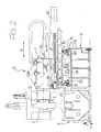
- reference A generally designates a mechanical machining unit usable for carrying out both milling operations on planar surfaces and boring operations of cylindrical bores.
- the unit A includes a lower base 2 which can, for example, consist of sheet metal elements electrically welded together or a cast iron body obtained by casting.
- a line which has one or more machining units of this type, constituting the stations by which the element is processed.
- the element to be processed is moved along the line by way of a transfer system of any known type.
- Figure 2 of the annexed drawings shows that the base 2 is suitably fixed to the floor and is placed adjacent to a fixed structure 3 of a system of any known type for moving the piece along the line (not shown in detail within the enclosed drawings).
- the element being produced (for example the cylinder head or the crankcase of an internal combustion engine) is moved and blocked with any systems of the known type.
- the machining unit A (figures 1-5) comprises a spindle D, mounted in such a way that will result evident in the following, having a rotation axis 5 on which both a milling cutter-shaped tool E (see figure 4), designed for carrying out milling operations on the planar surfaces 7 of the piece P, upon inclination of the spindle-axis of an angle ⁇ (figure 4), and a reaming tool F (see figure 5), upon pre-arrangement of the spindle-axis in an orthogonal direction of the surface 7 may be mounted.
- the base structure 2 presents a upper surface on which two tracks 8 (see figures 1, 2) are mounted, on which run the yokes 50, carried by a first slide B or lower slide, which is thus directed in a horizontal "X" direction (see arrows in figure 1), orthogonal to a horizontal "Z" direction.
- two tracks 8 are mounted on two supports 10 fixed at the base 2.
- yokes 50 run, supported on the lower side by the lower slide B.
- the two tracks 8 have two respective symmetry planes 12, arranged according an "upside-down V" at 90°. Such an arrangement, even though it is preferred as allows an optimal balance of the stresses resulting from the moving mass and the machining stresses, is definitely not essential, so it is not excluded that the two tracks 8 can be arranged in a common horizontal plane or with a different angle or on two different planes.
- the transmission could also be carried out by a belt with pulley or reducer, cylinder, hydraulic motor, etc.
- the screw 14 engages, in a per se known way, a nut of the ball recirculating type 15 connected to the structure of the lower slide B.
- the slide B can be provided with a hydraulic system for the blocking thereof in any selected position, similar to the one that will be described below with reference to the second slide of the unit.
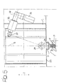
- a higher slide C is slidably supported by the lower slide B according to the horizontal "Z" direction, orthogonal to the "X" direction.
- the slide C is equipped with yokes 17 which are slide on tracks 18 fixed to the structure of the B slide.
- the two tracks 18 define two respective symmetry planes 19 arranged according to an "upside-down V" at 90°.
- the two tracks 18 are arranged in a single horizontal plane, either with different angle and/or on two different planes.
- the transmission can also be carried out through a belt with pulleys or reducer, cylinder, hydraulic motor, etc.
- the screw 21 engages, in a per se known way, a nut of the ball recirculating type 22 and it is connected to the slide C.
- the slide C is provided with a hydraulic system for the blocking thereof in any selected position, similar to the one that will be described below.
- a spindle-carrier structure 23 can oscillate around a vertical axis 24, with a cylindrical cavity in which the "electrospindle", comprised of the spindle D (axis 5) and the respective driving electric motor (not shown in the drawings), is mounted.
- the axis 5 of the spindle may be inclined with respect to the longitudinal Z movement direction of the slide C with a small angle ⁇ (for example according a 1:1.000 ratio).
- the milling cutter E (figure 4) with its frontal surface 6a forming the same angle with respect to the planar surface 7 to be worked.
- the milling cutter E has a peripheral surface 6b defining, together with the frontal surface 6a of the cutter machine 6, a circumferential edge 6c.
- the contact between the milling cutter and the planar surface to be worked is only executed in a substantially punctiform zone of the circumferential edge 6c. This is arranged when a milling operation of the surface 7 on the "P" element is required, for decreasing the milling cutter wear and improving the quality of the worked surface.
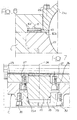
- Figure 7 shows in an enlarged scale the detail of the pin 25.
- the pin 25 has an annular flange 26 fixed through screws 27 at the spindle-carrier structure 23 and has one end 25a with a conical conformation which can be received within a conical cavity 28 as well, with a corresponding conformation obtained in a flange 29 fixed through screws 30 at the structure of the slide C. Due to such an assembly, the whole spindle-carrier structure 23 can then rotate in a horizontal plane relative to the slide C, by oscillating around the axis 24.
- the oscillating movement allowed for the spindle-carrier structure 23 around the axis 24 is reduced, as the obtainment of a relatively reduced inclination of the axis 5 of the spindle with respect to the Z direction is enough, for example corresponding to one millimeter cross movement in the "Z" direction, on a 1.000 millimeter length in the "X" direction.
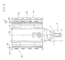
- the spindle-carrier support 23 forms a lower half-shell on which one or more half-shell 23b are fixed through screws 23c, so as to block the electro-spindle between the lower half-shell 23 and the higher semi-rings 23b.
- the semi-rings 23b are fixed by screws 23c on two planes 16a of the lower half-shell 23.
- the oscillation movement of the spindle-carrier structure 23 around the axis 24 is carried out by an electric motor 31 and a transmission box 32.
- the electric motor 31 drives the rotation of the shaft 33 and a screw 34, supported in rotation by the box 35.
- the screw 34 engages a leadscrew 37 comprised of a cylindrical body rotatably mounted around its axis within the spindle-carrier structure 23.
- the rotation of the electric motor 31 of a determined angle determines the oscillation of the whole spindle-carrier structure 23 around the axis 24.
- the spindle-carrier structure 23, placed in the required angular position with respect to the "P" element to be worked is then blocked on the structure of the slide C through a pistons system 40 diagrammatically shown in figure 1.
- FIG 6 a detail of a piston is shown in an enlarged scale.
- the pistons, sliding within the chamber 16f obtained in the structure of the slide C, are pushed by the oil coming from a duct 41 against the surface of the spindle-carrier structure 23, so as to block it by friction.
- the electric motor 20 is driven in order to positioning the milling cutter E in the "Z" direction on the surface of the element to be worked, while the motor 13 is driven for imparting the tool the required movement for carrying out machining of the surface 7, which is fixed (see figure 4).
- the boring operation (see fig. 5) is carried out by maintaining the axis 5 of the spindle parallel to the longitudinal "Z" direction and by positioning on the spindle D a reaming tool F.
- the axis 5 is inclined as shown in figure 4 by driving the electric motor 31.
- position sensors of the spindle-carrier structure 23 are preferably arranged with respect to the oscillation axis 24, which allow to carry out an automated control, according to a closed loop logic, of the structure position.
- the above described example allows to position the spindle-carrier structure relative to its oscillation axis 24 in any position between the position wherein the axis of the spindle D is parallel to the "Z" direction and an outermost position wherein the axis of the spindle D forms with the "Z" direction a maximum pre-established angle.
- This allows to fit the unit to different requirements of milling machining, which can need different values of the angle ⁇ . It is however possible to arrange a rotation system of the structure 23 relative to the simplified oscillation axis 24, which provides to position the structure only in the location with aligned spindle-axis and in a position corresponding to an assigned and fixed angle ⁇ .
- a pair of opposite support surfaces 60-61 and 62-63 forming together the assigned angle ⁇ and constituting a reference of the two possible operational positions of the structure 23, after which the structure movement between said position can be obtained for example by fluid-pistons 64 and 65 of the type 40 in figure 6, mounted on the structure of the slide C and laterally acting against the surfaces 61 and 63 of the semi-ring 23b, for pushing the structure 23 from two sides in either directions, against either surfaces 60 and 62 of reference.
- the reference surface, angular relative to the "Z" direction can be obtained in a single and replaceable element 66, mounted on the structure of the slide C, so as to allow a variation of the reference position if the angle ⁇ has to be changed.
- the spindle-carrier structure 23 is urged from the pistons 65 against the reaction plane 60, in this condition the surfaces 60 and 61 are in contact and the pistons 64 are not pressurized.
- the spindle-carrier structure 23 is urged from the pistons 64 against the reaction plane 62, in this condition the surfaces 62 and 63 are in contact and the pistons 65 are not pressurized.
Landscapes
- Engineering & Computer Science (AREA)
- Mechanical Engineering (AREA)
- Milling Processes (AREA)
- Automatic Tool Replacement In Machine Tools (AREA)
Applications Claiming Priority (2)
| Application Number | Priority Date | Filing Date | Title |
|---|---|---|---|
| IT000632A ITTO20030632A1 (it) | 2003-08-11 | 2003-08-11 | Unita' di lavorazione meccanica ad asportazione di truciolo, |
| ITTO20030632 | 2003-08-11 |
Publications (2)
| Publication Number | Publication Date |
|---|---|
| EP1506835A2 true EP1506835A2 (de) | 2005-02-16 |
| EP1506835A3 EP1506835A3 (de) | 2006-05-03 |
Family
ID=33561973
Family Applications (1)
| Application Number | Title | Priority Date | Filing Date |
|---|---|---|---|
| EP04017453A Withdrawn EP1506835A3 (de) | 2003-08-11 | 2004-07-23 | Bearbeitungseinheit mit orientierbarer Spindelachse zum Fräsen und Bohren |
Country Status (4)
| Country | Link |
|---|---|
| US (1) | US7093334B2 (de) |
| EP (1) | EP1506835A3 (de) |
| CA (1) | CA2475715C (de) |
| IT (1) | ITTO20030632A1 (de) |
Cited By (2)
| Publication number | Priority date | Publication date | Assignee | Title |
|---|---|---|---|---|
| CN103921118A (zh) * | 2014-03-28 | 2014-07-16 | 盐城工学院 | 一种曲轴箱立卧复合式多工位组合机床 |
| CN109304618A (zh) * | 2018-09-20 | 2019-02-05 | 大连中成精密机械有限公司 | 车底齐口机 |
Families Citing this family (10)
| Publication number | Priority date | Publication date | Assignee | Title |
|---|---|---|---|---|
| DE102004008457A1 (de) * | 2004-02-13 | 2005-09-01 | Ex-Cell-O Gmbh | Werkzeugmaschine und Verfahren zur Korrektur oder Kompensation von unterschiedlichen Werkzeuglängen in einer Werkzeugmaschine |
| JP2009061672A (ja) * | 2007-09-06 | 2009-03-26 | Canon Inc | インクジェット記録ヘッド |
| US8210781B2 (en) * | 2008-11-12 | 2012-07-03 | Buffalo Machinery Company Limited | Processing machine |
| EP3027356A2 (de) * | 2013-08-01 | 2016-06-08 | Grob-Werke GmbH & Co. KG | Bearbeitungsmaschine fuer die spanabhebende bearbeitung |
| JP6389618B2 (ja) * | 2014-02-24 | 2018-09-12 | Dmg森精機株式会社 | 工作機械の移動体案内機構 |
| CN112222844A (zh) * | 2020-11-05 | 2021-01-15 | 济南银国汇数控技术有限公司 | 数控钻铣床 |
| CN112589449A (zh) * | 2020-12-18 | 2021-04-02 | 南京库森科技有限公司 | 一种轮船的钻斜孔装置 |
| CN114770144A (zh) * | 2021-05-27 | 2022-07-22 | 张先中 | 一种数控机床角铣头 |
| CN117464378B (zh) * | 2023-12-27 | 2024-03-22 | 常州海特赐仁传动科技有限公司 | 一种钻孔攻牙切割加工模组及方法 |
| CN118204809B (zh) * | 2024-05-17 | 2024-08-27 | 山东海森智能装备有限公司 | 一种龙门镗孔加工设备 |
Family Cites Families (23)
| Publication number | Priority date | Publication date | Assignee | Title |
|---|---|---|---|---|
| US3494673A (en) * | 1967-03-10 | 1970-02-10 | Roy Milton Wilcox | Cleaning device for an exposed bearing surface |
| JPS591523B2 (ja) * | 1979-03-30 | 1984-01-12 | 東芝機械株式会社 | 角度可変な加工ユニット装置 |
| IT8433525U1 (it) * | 1984-08-07 | 1986-02-07 | Jobs Spa | Modello industriale avente per titolo testa operatrice per macchine utensili automatiche |
| US4850765A (en) * | 1987-12-17 | 1989-07-25 | Kennametal Inc. | Self-locking tool and socket |
| FR2641220B1 (fr) * | 1988-05-25 | 1994-06-03 | Somab Sa | Machine-outil multifonctions permettant des usinages complexes de pieces longues |
| DE4012999A1 (de) * | 1990-04-24 | 1991-10-31 | Josef Deuschl | Arbeitstisch mit verstellbarer neigung |
| US5084951A (en) * | 1990-11-30 | 1992-02-04 | Imta | Multi-axis tool positioner |
| GB2265561A (en) * | 1992-03-30 | 1993-10-06 | Yang Tai Her | Oblique guide column |
| DE9204823U1 (de) * | 1992-04-07 | 1992-06-11 | MAHO AG, 8962 Pfronten | Fräskopf |
| DE4316411C1 (de) * | 1993-05-17 | 1994-05-26 | Precise Praezisionsspindeln Gm | Schnellfrequenzspindel mit elektromotorischem Direktantrieb |
| DE19631675A1 (de) * | 1996-08-06 | 1998-02-12 | Werner Hermann Wera Werke | Werkzeugmaschine zum Abdachen von Zahnflanken eines Zahnrades |
| JP2788231B2 (ja) * | 1996-09-04 | 1998-08-20 | 川崎重工業株式会社 | 長尺バー材加工装置とその加工方法 |
| WO2000010768A1 (en) * | 1998-08-18 | 2000-03-02 | Unova Ip Corporation | New method of error compensation for angular errors in machining (droop compensation) |
| EP1002621B2 (de) * | 1998-11-20 | 2007-04-18 | Mikron SA Agno | Vorrichtung zur Erzeugung einer Relativbewegung |
| US6155756A (en) * | 1998-12-30 | 2000-12-05 | Musculoskeletal Transplant Foundation | Thread forming machine for bone material |
| JP3650706B2 (ja) * | 1999-04-27 | 2005-05-25 | 株式会社森精機製作所 | 工作機械 |
| IT1314043B1 (it) * | 1999-10-14 | 2002-12-03 | F M Elettromeccanica S R L | Testa per macchina utensile. |
| DE20002915U1 (de) * | 2000-02-18 | 2000-08-10 | Zimmer Guenther Stephan | Brems- und/oder Klemmvorrichtung für Führungen |
| ITBA20010022A1 (it) * | 2001-05-11 | 2002-11-11 | Jupiter Srl | Testa di precisione ad assi controllati con cambio automatico degli elettromandrini |
| DE50212129D1 (de) * | 2001-05-17 | 2008-06-05 | Chiron Werke Gmbh | Werkzeugmaschine zur Bearbeitung eines stangenförmigen Werkstücks |
| DE10130738B4 (de) * | 2001-06-19 | 2010-12-30 | Tbt Tiefbohrtechnik Gmbh + Co | Vorrichtung zum Verstellen einer Spindel |
| JP3907989B2 (ja) * | 2001-09-28 | 2007-04-18 | 東芝機械株式会社 | 主軸頭重心補正装置 |
| TW521677U (en) * | 2001-10-18 | 2003-02-21 | Ind Tech Res Inst | Gantry type hybrid parallel linkage 5-axis machine tool |
-
2003
- 2003-08-11 IT IT000632A patent/ITTO20030632A1/it unknown
-
2004
- 2004-07-23 EP EP04017453A patent/EP1506835A3/de not_active Withdrawn
- 2004-07-26 CA CA002475715A patent/CA2475715C/en not_active Expired - Fee Related
- 2004-08-11 US US10/915,466 patent/US7093334B2/en not_active Expired - Fee Related
Cited By (3)
| Publication number | Priority date | Publication date | Assignee | Title |
|---|---|---|---|---|
| CN103921118A (zh) * | 2014-03-28 | 2014-07-16 | 盐城工学院 | 一种曲轴箱立卧复合式多工位组合机床 |
| CN109304618A (zh) * | 2018-09-20 | 2019-02-05 | 大连中成精密机械有限公司 | 车底齐口机 |
| CN109304618B (zh) * | 2018-09-20 | 2023-09-12 | 大连中成精密机械有限公司 | 车底齐口机 |
Also Published As
| Publication number | Publication date |
|---|---|
| US20050034290A1 (en) | 2005-02-17 |
| US7093334B2 (en) | 2006-08-22 |
| CA2475715A1 (en) | 2005-02-11 |
| ITTO20030632A1 (it) | 2005-02-12 |
| EP1506835A3 (de) | 2006-05-03 |
| CA2475715C (en) | 2007-05-01 |
Similar Documents
| Publication | Publication Date | Title |
|---|---|---|
| US7093334B2 (en) | Machining unit with orientable spindle-axis for milling and boring operations | |
| KR930003338B1 (ko) | 타원형 피스톤을 선삭하기 위한 공작기계 및 타원형실린더를 보우링하기 위한 보우링 기계 | |
| US8926239B2 (en) | Method of forming piston pin holes and boring system therefor | |
| US20030041708A1 (en) | Vertical lathe, tool head for vertical lathe, rotary table apparatus for machine tool | |
| KR20130014035A (ko) | 크랭크축 베어링 보어의 피니싱을 위한 방법 및 기계가공 장치 | |
| US5984600A (en) | Broaching machine | |
| KR19980070810A (ko) | 다축공작기계 및 다축공작방법 | |
| KR20050098762A (ko) | 워크스테이션 및 트랜스퍼머신 등의 공작물고정유니트 | |
| US4359917A (en) | Portable on-site turning apparatus | |
| US4685661A (en) | Method and mechanism for fixturing objects | |
| GB2129355A (en) | Apparatus for machining a polygon profile on a workpiece | |
| US20050011924A1 (en) | Machining apparatus for forming cracking slot for connecting rod | |
| KR0156837B1 (ko) | 크랭크 샤프트의 오일 홀의 챔퍼 가공장치 | |
| US20050016350A1 (en) | Machining apparatus for forming cracking slot for connecting rod | |
| US7179029B2 (en) | Machine for machining workpieces, especially crankshafts and camshafts, with at least one internal cutter milling tool | |
| US5647788A (en) | Dressing of grinding wheels | |
| US4910993A (en) | Progressive former and method of producing same | |
| US4180945A (en) | Honing machine | |
| US4907372A (en) | Cylinder bore finishing apparatus tilt fixture | |
| US5113677A (en) | Apparatus and method for selectively forming a thickened edge on a plate of formable material | |
| US5435674A (en) | Process for manufacturing of workpieces, especially workpieces of motor vehicle drive assemblies, and also a device for application of the process | |
| US3803957A (en) | Variable elliptical and variable profile turning attachment for a lathe | |
| US7404347B2 (en) | Noncircular working device | |
| GB2073066A (en) | Work clamping fixture | |
| JPH028843B2 (de) |
Legal Events
| Date | Code | Title | Description |
|---|---|---|---|
| PUAI | Public reference made under article 153(3) epc to a published international application that has entered the european phase |
Free format text: ORIGINAL CODE: 0009012 |
|
| AK | Designated contracting states |
Kind code of ref document: A2 Designated state(s): AT BE BG CH CY CZ DE DK EE ES FI FR GB GR HU IE IT LI LU MC NL PL PT RO SE SI SK TR |
|
| AX | Request for extension of the european patent |
Extension state: AL HR LT LV MK |
|
| RIC1 | Information provided on ipc code assigned before grant |
Ipc: B23Q 1/48 20060101ALI20051216BHEP Ipc: B23Q 5/20 20060101ALI20051216BHEP Ipc: B23Q 1/28 20060101ALI20051216BHEP Ipc: B23Q 1/70 20060101AFI20041123BHEP |
|
| PUAL | Search report despatched |
Free format text: ORIGINAL CODE: 0009013 |
|
| AK | Designated contracting states |
Kind code of ref document: A3 Designated state(s): AT BE BG CH CY CZ DE DK EE ES FI FR GB GR HU IE IT LI LU MC NL PL PT RO SE SI SK TR |
|
| AX | Request for extension of the european patent |
Extension state: AL HR LT LV MK |
|
| RIC1 | Information provided on ipc code assigned before grant |
Ipc: B23Q 1/01 20060101ALI20060313BHEP Ipc: B23Q 1/48 20060101ALI20060313BHEP Ipc: B23Q 5/20 20060101ALI20060313BHEP Ipc: B23Q 1/28 20060101ALI20060313BHEP Ipc: B23Q 1/70 20060101AFI20041123BHEP |
|
| 17P | Request for examination filed |
Effective date: 20060704 |
|
| 17Q | First examination report despatched |
Effective date: 20061030 |
|
| AKX | Designation fees paid |
Designated state(s): AT BE BG CH CY CZ DE DK EE ES FI FR GB GR HU IE IT LI LU MC NL PL PT RO SE SI SK TR |
|
| GRAP | Despatch of communication of intention to grant a patent |
Free format text: ORIGINAL CODE: EPIDOSNIGR1 |
|
| STAA | Information on the status of an ep patent application or granted ep patent |
Free format text: STATUS: THE APPLICATION IS DEEMED TO BE WITHDRAWN |
|
| 18D | Application deemed to be withdrawn |
Effective date: 20070720 |