EP1506852A1 - Verfahren und vorrichtung zur herstellung eines luftreifens - Google Patents
Verfahren und vorrichtung zur herstellung eines luftreifens Download PDFInfo
- Publication number
- EP1506852A1 EP1506852A1 EP03725722A EP03725722A EP1506852A1 EP 1506852 A1 EP1506852 A1 EP 1506852A1 EP 03725722 A EP03725722 A EP 03725722A EP 03725722 A EP03725722 A EP 03725722A EP 1506852 A1 EP1506852 A1 EP 1506852A1
- Authority
- EP
- European Patent Office
- Prior art keywords
- rigid core
- vulcanizing mold
- mold
- green tire
- movable seal
- Prior art date
- Legal status (The legal status is an assumption and is not a legal conclusion. Google has not performed a legal analysis and makes no representation as to the accuracy of the status listed.)
- Granted
Links
- 238000004519 manufacturing process Methods 0.000 title claims abstract description 9
- 238000000034 method Methods 0.000 title claims abstract description 7
- 238000004073 vulcanization Methods 0.000 claims abstract description 40
- 238000007789 sealing Methods 0.000 claims abstract description 5
- 239000011324 bead Substances 0.000 claims description 23
- 229910052751 metal Inorganic materials 0.000 claims description 6
- 239000002184 metal Substances 0.000 claims description 6
- 230000006835 compression Effects 0.000 claims description 5
- 238000007906 compression Methods 0.000 claims description 5
- 238000003825 pressing Methods 0.000 claims description 2
- 230000035515 penetration Effects 0.000 description 3
- 210000003371 toe Anatomy 0.000 description 3
- 238000006073 displacement reaction Methods 0.000 description 2
- 229910000838 Al alloy Inorganic materials 0.000 description 1
- 229910000831 Steel Inorganic materials 0.000 description 1
- 238000000465 moulding Methods 0.000 description 1
- 229910052705 radium Inorganic materials 0.000 description 1
- HCWPIIXVSYCSAN-UHFFFAOYSA-N radium atom Chemical compound [Ra] HCWPIIXVSYCSAN-UHFFFAOYSA-N 0.000 description 1
- 230000001105 regulatory effect Effects 0.000 description 1
- 239000010959 steel Substances 0.000 description 1
Images




Classifications
-
- B—PERFORMING OPERATIONS; TRANSPORTING
- B29—WORKING OF PLASTICS; WORKING OF SUBSTANCES IN A PLASTIC STATE IN GENERAL
- B29D—PRODUCING PARTICULAR ARTICLES FROM PLASTICS OR FROM SUBSTANCES IN A PLASTIC STATE
- B29D30/00—Producing pneumatic or solid tyres or parts thereof
- B29D30/06—Pneumatic tyres or parts thereof (e.g. produced by casting, moulding, compression moulding, injection moulding, centrifugal casting)
- B29D30/0601—Vulcanising tyres; Vulcanising presses for tyres
- B29D30/0661—Rigid cores therefor, e.g. annular or substantially toroidal cores
-
- B—PERFORMING OPERATIONS; TRANSPORTING
- B29—WORKING OF PLASTICS; WORKING OF SUBSTANCES IN A PLASTIC STATE IN GENERAL
- B29C—SHAPING OR JOINING OF PLASTICS; SHAPING OF MATERIAL IN A PLASTIC STATE, NOT OTHERWISE PROVIDED FOR; AFTER-TREATMENT OF THE SHAPED PRODUCTS, e.g. REPAIRING
- B29C37/00—Component parts, details, accessories or auxiliary operations, not covered by group B29C33/00 or B29C35/00
- B29C37/005—Compensating volume or shape change during moulding, in general
-
- B—PERFORMING OPERATIONS; TRANSPORTING
- B29—WORKING OF PLASTICS; WORKING OF SUBSTANCES IN A PLASTIC STATE IN GENERAL
- B29D—PRODUCING PARTICULAR ARTICLES FROM PLASTICS OR FROM SUBSTANCES IN A PLASTIC STATE
- B29D30/00—Producing pneumatic or solid tyres or parts thereof
- B29D30/06—Pneumatic tyres or parts thereof (e.g. produced by casting, moulding, compression moulding, injection moulding, centrifugal casting)
- B29D30/0601—Vulcanising tyres; Vulcanising presses for tyres
-
- B—PERFORMING OPERATIONS; TRANSPORTING
- B29—WORKING OF PLASTICS; WORKING OF SUBSTANCES IN A PLASTIC STATE IN GENERAL
- B29D—PRODUCING PARTICULAR ARTICLES FROM PLASTICS OR FROM SUBSTANCES IN A PLASTIC STATE
- B29D30/00—Producing pneumatic or solid tyres or parts thereof
- B29D30/06—Pneumatic tyres or parts thereof (e.g. produced by casting, moulding, compression moulding, injection moulding, centrifugal casting)
- B29D30/08—Building tyres
- B29D30/10—Building tyres on round cores, i.e. the shape of the core is approximately identical with the shape of the completed tyre
-
- B—PERFORMING OPERATIONS; TRANSPORTING
- B29—WORKING OF PLASTICS; WORKING OF SUBSTANCES IN A PLASTIC STATE IN GENERAL
- B29D—PRODUCING PARTICULAR ARTICLES FROM PLASTICS OR FROM SUBSTANCES IN A PLASTIC STATE
- B29D30/00—Producing pneumatic or solid tyres or parts thereof
- B29D30/06—Pneumatic tyres or parts thereof (e.g. produced by casting, moulding, compression moulding, injection moulding, centrifugal casting)
- B29D30/0601—Vulcanising tyres; Vulcanising presses for tyres
- B29D30/0606—Vulcanising moulds not integral with vulcanising presses
- B29D2030/0607—Constructional features of the moulds
- B29D2030/062—Means for sealing the tyre against the mould in the bead areas
- B29D2030/0621—Means for sealing the tyre against the mould in the bead areas to seal the bead portions against the mould i.e. by using pressing devices
-
- B—PERFORMING OPERATIONS; TRANSPORTING
- B29—WORKING OF PLASTICS; WORKING OF SUBSTANCES IN A PLASTIC STATE IN GENERAL
- B29D—PRODUCING PARTICULAR ARTICLES FROM PLASTICS OR FROM SUBSTANCES IN A PLASTIC STATE
- B29D30/00—Producing pneumatic or solid tyres or parts thereof
- B29D30/06—Pneumatic tyres or parts thereof (e.g. produced by casting, moulding, compression moulding, injection moulding, centrifugal casting)
- B29D30/0601—Vulcanising tyres; Vulcanising presses for tyres
- B29D30/0606—Vulcanising moulds not integral with vulcanising presses
- B29D2030/0607—Constructional features of the moulds
- B29D2030/062—Means for sealing the tyre against the mould in the bead areas
- B29D2030/0621—Means for sealing the tyre against the mould in the bead areas to seal the bead portions against the mould i.e. by using pressing devices
- B29D2030/0623—Means for sealing the tyre against the mould in the bead areas to seal the bead portions against the mould i.e. by using pressing devices the pressing devices being flexible, e.g. annular elements being relatively elastic and deformable
-
- B—PERFORMING OPERATIONS; TRANSPORTING
- B29—WORKING OF PLASTICS; WORKING OF SUBSTANCES IN A PLASTIC STATE IN GENERAL
- B29L—INDEXING SCHEME ASSOCIATED WITH SUBCLASS B29C, RELATING TO PARTICULAR ARTICLES
- B29L2030/00—Pneumatic or solid tyres or parts thereof
Definitions
- the present invention relates to a method and an apparatus for manufacturing a pneumatic tire using a rigid core in the toroidal shape.
- the rigid core is subjected to an excessive gripping force from the vulcanizing mold and broken upon vulcanization. That is, when the green tire is transported into the vulcanizing mold together with the rigid core, the temperature of the rigid core is a normal temperature, about 20°C, for example, or if it has been pre-heated, the temperature is about 100°, while the temperature of the vulcanizing mold is held at a temperature somewhat lower than 170°C, which is the vulcanization temperature, because its heat capacity is large.
- the vulcanizing mold After the vulcanizing mold is brought into contact with the inner end of the rigid core by closing the vulcanizing mold in this state, if the vulcanizing medium is supplied into the vulcanizing mold and the rigid core, the rigid core has its temperature rise from the temperature at transportation to a vulcanizing temperature by about 150°C or 70°C and is subjected to large thermal expansion. But the vulcanizing mold has its temperature hardly rise and is not substantially expanded thermally, and moreover, its movement is strongly regulated by a large clamping force, which exerts an excessive gripping force to a contact portion of rigid core with the vulcanizing mold and might break the rigid core.
- a gap somewhat narrower than the thermal expansion of the rigid core may be provided between the inner end of the rigid core and the vulcanizing mold when the vulcanizing mold is closed.
- the green rubber might protrude out of the gap and generate a burr.
- thermal expansion rate (linear expansion rate) of the rigid core is larger than that of the vulcanizing mold, for example, when the vulcanizing mold is made of steel, while the rigid core is formed by an aluminum alloy or the like.
- a method for manufacturing a pneumatic tire in which a green tire is formed on an outer surface of a rigid core, the green tire is transported into a vulcanizing mold together with a rigid core, and the vulcanizing mold is closed to form a vulcanization space for sealing and storing the green tire between the vulcanizing mold and the rigid core so that the green tire is vulcanized in the vulcanization space, wherein an annular movable seal supported by either one of the vulcanizing mold and the rigid core is urged toward the surface of the other so as to prevent generation of a gap between the vulcanizing mold and the rigid core when the vulcanizing mold is closed and to absorb change in the shape of the rigid core at vulcanization.
- an apparatus for manufacturing a pneumatic tire provided with a rigid core for forming a green tire on the outer surface and a vulcanizing mold which can transport the green tire together with the rigid core, in which the vulcanizing mold is closed to form a vulcanization space to seal and store the green tire between the vulcanizing mold and the rigid core and the green tire within the vulcanization space is vulcanized, wherein an annular movable seal supported by either one of the vulcanizing mold and the rigid core is provided, and the movable seal is urged toward the surface of the other of the vulcanizing mold and the rigid core so as to prevent generation of a gap between the vulcanizing mold and the rigid core when the vulcanizing mold is closed and to absorb change in the shape of the rigid core at vulcanization.
- the annular movable seal supported by either one of the vulcanizing mold and the rigid core is urged toward the surface of the other to prevent generation of a gap between the vulcanizing mold and the rigid core at closure of the vulcanizing mold so that the unvulcanized rubber does not protrude out of the gap between the vulcanizing mold and the rigid core at vulcanization and therefore, generation of a burr can be surely prevented.
- the temperature of the rigid core which has been at a normal temperature or a pre-heated temperature, rises to the vulcanization temperature and the rigid core is thereby thermally expanded.
- the annular movable seal supported by the vulcanizing mold or the rigid core absorbs change in the shape of the rigid core at vulcanization, gripping force acting on the rigid core rarely changes and as a result, breakage of the rigid core can be prevented. And this function is surely exerted even if there is a large difference in the thermal expansion rate between the rigid core and the vulcanizing mold.
- either one of the above vulcanizing mold and the rigid core has an annular recess portion for storing the movable seal and is further provided with an urging means arranged in the annular recess portion for pressing the movable seal toward the surface of the other of the vulcanizing mold and the rigid core.
- the annular recess portion is provided at the rigid core, and by aligning the outer surface of the movable seal before closure of the vulcanizing mold with the surface of the rigid core adjacent to both sides of said annular recess portion, a step displacement on the inner surface of the green tire based on the step generated at the border between the movable seal and the rigid core can be prevented.
- the inner surface portion of the vulcanizing mold to which the outer surface of the movable seal is brought into an elastic contact is formed as a projecting portion with the width narrower than said annular recess portion.
- the urging means is a compression spring made of metal. In this case, it can apply an urging force to the movable seal surely for a long time at a high temperature.
- the urging means bring the movable seal into an elastic contact with the surface of the other of the above vulcanizing mold and the rigid core at a contact pressure of 1 to 3 MPa. In this case, a fear of protrusion of the green tire or deformation of the vulcanizing mold or the rigid core can be eliminated.
- the movable seal is constituted to be supported by the rigid core at a position adjacent to the bead tip end position of the green tire or supported by the vulcanizing mold at a position adjacent to the bead bottom position of the green tire.
- FIG. 1 is a partially broken plan view showing a rigid core according to a first preferred embodiment of the present invention in the state where a green tire is formed.
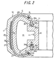
- FIG. 2 is a sectional view seen from an arrow of 2-2 in FIG. 1.
- FIG. 3 is a front sectional view of a vulcanizing apparatus which stores a green tire together with a rigid core.
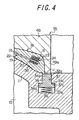
- FIG. 4 is a front sectional view of the neighborhood of a bead portion at vulcanization.
- FIG. 5 is a front sectional view as with FIG. 3 showing a vulcanizing apparatus according to a second preferred embodiment of the present invention in the state where a green tire is stored together with a rigid core.
- FIG. 6 is a front sectional view of the neighborhood of a bead portion at vulcanization.
- FIGS. 1 through 4 A first preferred embodiment of the present invention will be hereinafter described referring to FIGS. 1 through 4.
- reference numeral 11 represents a rigid core made of metal generally presenting a toroidal shape.
- the rigid core 11 has an outer surface on the outer side in the radial direction in the same shape as the inner surface of a vulcanized pneumatic tire (product tire).
- the rigid core 11 is assembled by closely aligning a plurality of arcuate core segments 12 in the circumferential direction.
- the core segment 12 is comprised of two types of segments: a sectored segment 12a whose planar shape is a sector and an angular segment 12b in almost the ridge shape, and they are arranged alternately in the circumferential direction.
- a penetration chamber 14 extending in the circumferential direction is formed, and these penetration chambers 14 are opened at both ends in the circumferential direction of the core segment 12.
- all the penetration chambers 14 penetrate in the ring state so as to constitute a vulcanizing medium chamber 15 in the consecutive ring state for supplying a vulcanizing medium into the rigid core 11.
- Reference numeral 18 represents a green tire mounted to the outside of the rigid core 11.
- the green tire 18 is formed on the outside of the rigid core 11 by applying, for example, tire constituting members such as unvulcanized rubber ribbon, wire, cord, etc. to the rigid core 11 in order as below. That is, first, the unvulcanized rubber ribbon is applied to the outside of the rigid core 11 in the spiral state by a large number of times so as to form an inner liner 19 and then, a bead wire 20 is wound on the outside of the inner liner 19 in a bead portion B in the spiral state by a plurality of times.
- tire constituting members such as unvulcanized rubber ribbon, wire, cord, etc.
- a carcass cord 21 is applied in the meridian direction while folding it at both bead portions B while displacing the application in the circumferential direction by a large number of times to form a carcass layer 22.
- a bead wire 23 is wound in the spiral state by a plurality of times to form a bead core 24 holding the carcass layer 22 with said bead wire 20 between them.
- a belt cord 26 is applied helically by a large number of times to form a belt layer 27, and then, an unvulcanized rubber ribbon is applied to the outside of the carcass layer 22 in a sidewall portion S in the spiral state by a large number of times to form a side tread 28 and by applying the unvulcanized rubber ribbon to the outside of the belt layer 27 helically by a large number of times to form a top tread 29 so that a green tire 18 is formed.
- arcuate recesses 31a and 31b are formed extending in the circumferential direction, respectively, with the same radium of curvature. If the sectored segment 12a and the angular segment 12b are assembled in the close state in the circumferential direction as mentioned above, said arcuate recesses 31a and 31b continue and form a pair of annular recesses 32 extending, respectively, along the bead toe U on the upper face and the lower face of the rigid core 11 in the neighborhood of both the bead toes U of the green tire 18.
- These annular recesses 32 are comprised of a narrow width portion 32a located on the face side and a wide width portion 32b which is wider than the narrow width portion 32a located on the inner side and have the T-shaped cross section. And at the border between the narrow width portion 32a and the wide width portion 32b of each of the annular recesses 32, a stepped surface 32c which is parallel with the upper and the lower faces of the rigid core 11 and functions as a stopper is formed.
- arcuate pieces 33a and 33b with the length equal to these arcuate recesses 31a and 31b, respectively, are inserted movably in the depth direction.
- These arcuate pieces 33a and 33b continuously constitute an annular movable seal 34 when the sectored segment 12a and the angled segment 12b are assembled in the close state in the circumferential direction.
- the annular movable seal 34 is movably inserted in the depth direction of the annular recess 32.
- these movable seals 34 are also constituted as with the annular recess 32 by a narrow width portion 34a located on the face side and having the width equal to the narrow width portion 32a and a wide width portion 34b located on the inner side and having the width equal to the wide width portion 32b and presents the T-shaped cross section. And at the border between the narrow width portion 34a and the wide width portion 34b of each of the movable seals 34, a stepped surface 34c which can be brought into contact with the stepped surface 32c of the annular recess 32 is formed.
- each of the movable seals 34 is moved to the projecting side, but the movement is restrained by contact of the stepped surface 34c into the stepped surface 32c of the annular recess 32 and stopped at the position concerned.
- the outer surface of each of the movable seal 34 is located on the extension of the upper and the lower faces of the rigid core 11 located on both sides of the annular recess 32 to which the movable seal 34 is inserted, and as a result, the outer surface of the movable seal 34 is made flush with the upper and the lower faces of the rigid core 11, and there exists no step at the border of them.
- the green tire 18 is transported together with the rigid core 11 by a conveying device (not shown) to a vulcanizing device 41 for vulcanization.
- the above mentioned vulcanizing device 41 has, as shown in FIGS. 3 and 4, a lower base 42, and on this lower base 42, a lower platen 43 into which a high-temperature and high-pressure vulcanizing medium is supplied at vulcanization is fixed, wherein on this lower platen 43, a lower mold 44 for molding a lower sidewall portion S and a lower bead portion B of the green tire 18 is mounted.
- a reference numeral 45 represents an upper base placed above the lower base 42 and having an upper platen 46 fixed to its lower face as with the lower platen 43.
- the upper base 45 is elevated up and down by a cylinder (not shown) to approach to/separate from the lower base 42.
- a cylinder not shown
- an upper plate 48 connected to the tip end of a piston rod 47 in the cylinder is placed, and this upper plate 48 can be elevated by operation of the cylinder separately from the upper base 45.
- a reference numeral 49 represents an upper mold fixed to the lower face of the upper plate 48 and elevated up and down with the upper plate 48 to approach to/separate from the lower mold 44.
- the upper mold 49 molds an upper sidewall portion S and an upper bead portion B of the green tire 18 at vulcanization.
- a reference numeral 50 represents an outer ring placed surrounding the upper plate 48 from outside in the radial direction.
- the upper end of the outer ring 50 is fixed to the outer end in the radial direction of the upper base 45.
- an inner circumference 50a of the outer ring 50 is an inclined face expanded downward (part of a conical face).
- Reference numeral 52 represents a plurality of sector segments aligned in the circumferential direction.
- the sector segment 52 is supported movably in the radial direction by its upper end by the upper plate 48 outside in the radial direction from the upper mold 49, and the vulcanizing medium is supplied into its inside at vulcanization.
- a sector mold member 53 is mounted on an inner circumference of each of the sector segments 52, and these mold members 53 mold a tread portion T of the green tire 18 at vulcanization.
- each of the sector segments 52 On an outer circumference 52a of each of the sector segments 52, an inclined face (part of a conical face) with the same gradient as the inner circumference 50a of the outer ring 50 is formed, and these inner circumference 50a and the outer circumference 52a are connected with a dovetail joint and slidably engaged.
- the sector segment 52 and the sector mold member 53 are moved in the radial direction by a wedge action of the inner and the outer circumferences 50a and 52a in synchronization while being supported by the upper plate 48.
- the above mentioned sector segment 52 and the sector mold member 53 generally constitute a sector mold 54.
- the green tire 18 is vulcanized while being surrounded by the lower mold 44, the upper mold 49, the sector mold 54 and the rigid core 11, when the high-temperature and high-pressure vulcanizing medium is supplied from a supply source, not shown, into the lower platen 43, the upper platen 46, the sector segment 52 and the vulcanizing medium chamber 15.
- the above-mentioned tire constituting members (unvulcanized rubber ribbon, wire, cord, etc.) are supplied and applied in sequence onto its outer surface so as to form the green tire 18 comprised of the inner liner 19, the carcass layer 22, the bead core 24, the belt layer 27, the side tread 28 and the top tread 29.
- the rigid core 11 with the green tire 18 formed outside is transported by the conveying device to the vulcanizing device 41.
- the rigid core 11 and the green tire 18 are heated to a normal temperature or a pre-heat temperature as mentioned above, but in any case, the temperature is relatively low, while the lower mold 44, the upper mold 49 and the sector mold 55 are at a high temperature close to the vulcanizing temperature since the vulcanizing device 41 has a large heat capacity.
- the transported rigid core 11 and the green tire 18 are loaded laterally on the open lower mold 44.
- the upper base 45 and the upper plate 48 are integrally lowered. And when the sector segment 52 is brought into contact with the upper face of the lower base 42 and the upper mold 49 is brought into contact with the green tire 18, the lowering of the upper plate 48 is stopped.
- the contact pressure between the movable seal 34 and the upper face of the lower mold 44 and the lower face of the upper mold 49 at the time when the movable seal 34 is pushed into the annular recess 32 by the lower mold 44 and the upper mold 49 is preferably within the range of 1 to 3 MPa adjusting an urging force of the coil spring 36 (spring constant). That is because if it is less than 1MPa, the unvulcanized rubber might protrude from between the movable seal 34 and the lower mold 44 and the upper mold 49 at vulcanization which will be described later, while if it exceeds 3MPa, the projection portions 44a and 49a of the lower mold 44 and the upper mold 49 might be deformed.
- the sector mold 54 is moved to the inner limit in the radial direction so as to close the vulcanizing mold 55, and the green tire 18 is sealed and stored in the vulcanization space 56.
- the high-temperature and high-pressure vulcanizing medium is supplied to the lower platen 43, the upper platen 46, the sector segment 52 and the vulcanizing medium chamber 15 so as to vulcanize the green tire 18.
- the rigid core 11 which had been at a normal temperature or a pre-heat temperature at vulcanization is heated by the vulcanizing medium and has the temperature rise to the vulcanizing temperature and is thermally expanded.
- the lower mold 44 and the upper mold 49 only pushes (moves) the movable seal 34 further into the inside of the annular recess 32 against the coil spring 36, but the gripping force to the rigid core 11 hardly changes, whereby breakage of the rigid core 11 can be prevented. And this function is surely exerted even if there is a large difference in thermal expansion rate between the rigid core 11 and the vulcanizing mold 55.
- the vulcanizing mold 55 is opened by the operation reverse to the above and then, the rigid core 11 to which the vulcanized tire is attached is transported to a work position by the transporting device. And at this work position, the core segment 12 is disassembled and taken out from inside the vulcanized tire sequentially.
- FIGS. 5 and 6 show a second preferred embodiment of the present invention.
- an annular recess 60 with the cross section in the T-shape is formed so that it extends along a bead heel H on the upper face of the lower mold 44 and the lower face of the upper mold 49, respectively, in the neighborhood of both the bead heels H of the green tire 18.
- annular movable seal 61 with the cross section in the T-shape is movably inserted into each of the annular recesses 60 in the depth direction of the annular recess 60, and a coil spring 62 as an urging means for urging the movable seal 61 toward the rigid core 11 is stored in each of the annular recesses 60 between the movable seal 61 and the bottom face of the annular recess 60.
- both the movable seals 61 are slightly pushed in by the rigid core 11 against the coil spring 62 so that a gap between the rigid core 11 and the lower mold 44 and the upper mold 49 is eliminated so as to prevent protrusion of unvulcanized rubber from between the rigid core 11 and the lower mold 44 and the upper mold 49 at vulcanization, and to absorb thermal expansion of the rigid core 11 at vulcanization by the movable seal 61 by further pushing in the movable seal 61 against the coil spring 62 so as to prevent breakage of the rigid core 11.
- the outer face at the outer end in the radial direction of the movable seal 61 is located flush on the extension of the upper face and the lower face of the lower mold 44 and the upper mold 49 adjacent to this outer face, but the outer face at the inner end in the radial direction protrudes from the upper face and the lower face of the lower mold 44 and the upper mold 49 adjacent to this outer face in order to exert the same function as the projection portions 44a and 49a.
- the other constitutions and action are the same as those of the first preferred embodiment.
- such a state can be prevented that the unvulcanized rubber protrudes from between the rigid core and the vulcanizing mold at vulcanization to generate burr or that the rigid core is subjected to an excessive gripping force from the vulcanizing mold to be broken.
- the vulcanizing mold 55 is constituted by the lower mold 44, the upper mold 49 and the sector mold 54, but the present invention may be applied to a vulcanizing mold made only of a lower mold and an upper mold.
- a lower half of a tread portion of a green tire is molded by a lower mold, while an upper half by an upper mold.
- the outer face of the movable seal 34 before vulcanization is made flush with the upper face and the lower face of the rigid core 11, but in the present invention, the outer face of the movable seal may protrude in advance from the upper face and the lower face of the rigid core by the total amount of being pushed-in of the movable seal. In this case, the outer face of the movable seal is flush with the upper face and the lower face of the rigid core when vulcanization is finished.
Landscapes
- Engineering & Computer Science (AREA)
- Mechanical Engineering (AREA)
- Moulds For Moulding Plastics Or The Like (AREA)
- Heating, Cooling, Or Curing Plastics Or The Like In General (AREA)
- Tyre Moulding (AREA)
Applications Claiming Priority (3)
| Application Number | Priority Date | Filing Date | Title |
|---|---|---|---|
| JP2002127936A JP4056290B2 (ja) | 2002-04-30 | 2002-04-30 | 空気入りタイヤの製造方法および装置 |
| JP2002127936 | 2002-04-30 | ||
| PCT/JP2003/005549 WO2003092989A1 (fr) | 2002-04-30 | 2003-04-30 | Procede et appareil destines a fabriquer un pneumatique |
Publications (3)
| Publication Number | Publication Date |
|---|---|
| EP1506852A1 true EP1506852A1 (de) | 2005-02-16 |
| EP1506852A4 EP1506852A4 (de) | 2005-06-08 |
| EP1506852B1 EP1506852B1 (de) | 2006-03-22 |
Family
ID=29397254
Family Applications (1)
| Application Number | Title | Priority Date | Filing Date |
|---|---|---|---|
| EP03725722A Expired - Lifetime EP1506852B1 (de) | 2002-04-30 | 2003-04-30 | Verfahren und vorrichtung zur herstellung eines luftreifens |
Country Status (7)
| Country | Link |
|---|---|
| US (1) | US7648668B2 (de) |
| EP (1) | EP1506852B1 (de) |
| JP (1) | JP4056290B2 (de) |
| CN (1) | CN100431828C (de) |
| DE (1) | DE60304174T2 (de) |
| ES (1) | ES2260620T3 (de) |
| WO (1) | WO2003092989A1 (de) |
Cited By (6)
| Publication number | Priority date | Publication date | Assignee | Title |
|---|---|---|---|---|
| WO2007034779A1 (ja) | 2005-09-20 | 2007-03-29 | Bridgestone Corporation | タイヤの製造方法およびタイヤ加硫モールド |
| WO2007072511A1 (en) | 2005-12-19 | 2007-06-28 | Pirelli Tyre S.P.A. | Method and apparatus for manufacturing pneumatic tyres |
| WO2012072425A1 (de) * | 2010-12-01 | 2012-06-07 | Vmi Holland B.V. | Reifenaufbauvorrichtung sowie verfahren zur reifenherstellung |
| EP2349668A4 (de) * | 2008-11-21 | 2012-11-28 | Michelin & Cie | Vorrichtung und verfahren zum aushärten eines kautschukartigen artikels |
| US9415553B2 (en) | 2011-05-04 | 2016-08-16 | Compagnie Generale Des Etablissements Michelin | Apparatus and method for curing a rubber like article |
| EP3103609A4 (de) * | 2014-02-04 | 2017-03-08 | Bridgestone Corporation | Reifenvulkanisierungsverfahren, reifenherstellungsverfahren und reifen |
Families Citing this family (23)
| Publication number | Priority date | Publication date | Assignee | Title |
|---|---|---|---|---|
| KR101022397B1 (ko) * | 2003-12-29 | 2011-03-15 | 피렐리 타이어 소시에떼 퍼 아찌오니 | 타이어 제조 방법 |
| JP4438506B2 (ja) * | 2004-05-07 | 2010-03-24 | 横浜ゴム株式会社 | 空気入りタイヤの加硫成形装置 |
| JP4412050B2 (ja) * | 2004-05-07 | 2010-02-10 | 横浜ゴム株式会社 | 空気入りタイヤの加硫成形方法 |
| JP4615933B2 (ja) * | 2004-08-18 | 2011-01-19 | 株式会社ブリヂストン | タイヤ製造用コア |
| JP2006088472A (ja) * | 2004-09-22 | 2006-04-06 | Bridgestone Corp | 加硫装置及び加硫方法 |
| JP4608351B2 (ja) * | 2005-04-04 | 2011-01-12 | 株式会社ブリヂストン | 空気入りタイヤの製造方法 |
| JP4749032B2 (ja) * | 2005-05-18 | 2011-08-17 | 株式会社ブリヂストン | タイヤ加硫用金型 |
| JP2007050596A (ja) * | 2005-08-18 | 2007-03-01 | Bridgestone Corp | タイヤ加硫成型金型及び加硫成型方法 |
| CN100375669C (zh) * | 2005-12-23 | 2008-03-19 | 徐慕贤 | 轮胎定型硫化机中心机构高温内压介质进出管硬管结构 |
| JP2007190850A (ja) * | 2006-01-20 | 2007-08-02 | Bridgestone Corp | タイヤの加硫方法 |
| WO2009054185A1 (ja) * | 2007-10-25 | 2009-04-30 | Fuji Seiko Co., Ltd. | ボディプライの折り返し装置 |
| WO2009157949A1 (en) * | 2008-06-27 | 2009-12-30 | Michelin Recherche Et Technique S.A. | Mold for tire with floating mold back ring |
| WO2010002392A1 (en) * | 2008-06-30 | 2010-01-07 | Michelin Recherche Et Technique S.A. | Tire mold with positive mold opening system |
| JP5200124B2 (ja) * | 2011-01-28 | 2013-05-15 | 住友ゴム工業株式会社 | 空気入りタイヤの製造方法 |
| JP5662883B2 (ja) * | 2011-06-23 | 2015-02-04 | 住友ゴム工業株式会社 | 剛性中子 |
| JP5432955B2 (ja) * | 2011-06-24 | 2014-03-05 | 住友ゴム工業株式会社 | 剛性中子 |
| JP5261541B2 (ja) * | 2011-06-24 | 2013-08-14 | 住友ゴム工業株式会社 | 剛性中子 |
| JP5667606B2 (ja) * | 2012-07-30 | 2015-02-12 | 住友ゴム工業株式会社 | タイヤ形成用の剛性中子 |
| EP2905115B1 (de) * | 2012-10-02 | 2020-02-26 | Sumitomo Rubber Industries, Ltd. | Reifenvulkanisierungsverfahren und reifenherstellungsverfahren |
| US10576665B2 (en) * | 2016-08-12 | 2020-03-03 | Toyo Tire Corporation | Tire vulcanizer |
| WO2018029729A1 (ja) * | 2016-08-12 | 2018-02-15 | 東洋ゴム工業株式会社 | タイヤ加硫金型、タイヤ加硫装置及びタイヤの製造方法 |
| CN108274792B (zh) * | 2018-04-04 | 2020-05-22 | 山东豪迈机械科技股份有限公司 | 一种密封装置及抽真空轮胎模具 |
| CN111283922B (zh) * | 2020-03-11 | 2023-04-11 | 青岛海泰克机械科技有限公司 | 一种轮胎硫化用模具及其点对点收集废气的方法 |
Family Cites Families (12)
| Publication number | Priority date | Publication date | Assignee | Title |
|---|---|---|---|---|
| US4181488A (en) * | 1976-07-19 | 1980-01-01 | Caterpillar Tractor Co. | Tire tread forming mold body |
| ES2025339B3 (es) * | 1986-04-25 | 1992-03-16 | Cie Generale Des Etablissements Michelin-Michelin & Cie | Molde rigido para el moldeado y la vulcanizacion de neumaticos. |
| FR2597783B1 (fr) | 1986-04-25 | 1988-08-26 | Michelin & Cie | Moule rigide pour le moulage et la vulcanisation de pneumatiques |
| US5536348A (en) * | 1995-06-30 | 1996-07-16 | The Goodyear Tire & Rubber Company | Method of assembly of a precured tire tread to an unvulcanized casing |
| FR2742377A1 (fr) * | 1995-12-19 | 1997-06-20 | Michelin & Cie | Moule a noyau rigide pour bandes de roulement annulaires notamment destinees au rechapage de pneumatiques |
| TR199902228T2 (xx) * | 1997-03-25 | 2000-07-21 | The Goodyear Tire & Rubber Company | Vulkanize astarl� pn�matik ta��t lastikleri ve astar�n kullan�m y�ntemi. |
| US6113833A (en) * | 1997-07-22 | 2000-09-05 | Bridgestone Corporation | Segmented toroidal core for manufacturing pneumatic tires |
| JP3770705B2 (ja) | 1997-07-22 | 2006-04-26 | 株式会社ブリヂストン | タイヤ製造用内型 |
| JP4131587B2 (ja) | 1997-08-15 | 2008-08-13 | 株式会社ブリヂストン | 空気入りタイヤおよびその成形方法 |
| JP2000052347A (ja) * | 1998-08-07 | 2000-02-22 | Sumitomo Rubber Ind Ltd | タイヤ成形用金型及びタイヤ製法 |
| US6479008B1 (en) * | 1999-03-26 | 2002-11-12 | Pirelli Pneumatici S.P.A. | Method and apparatus for moulding and curing tires for vehicle wheels |
| ATE464174T1 (de) * | 1999-08-10 | 2010-04-15 | Mft Fr Pneumatiques Michelin | Steifer kern in zwei teilen, zur herstellung von luftreifen |
-
2002
- 2002-04-30 JP JP2002127936A patent/JP4056290B2/ja not_active Expired - Fee Related
-
2003
- 2003-04-30 ES ES03725722T patent/ES2260620T3/es not_active Expired - Lifetime
- 2003-04-30 EP EP03725722A patent/EP1506852B1/de not_active Expired - Lifetime
- 2003-04-30 DE DE60304174T patent/DE60304174T2/de not_active Expired - Lifetime
- 2003-04-30 CN CNB038126397A patent/CN100431828C/zh not_active Expired - Fee Related
- 2003-04-30 WO PCT/JP2003/005549 patent/WO2003092989A1/ja not_active Ceased
- 2003-04-30 US US10/513,000 patent/US7648668B2/en not_active Expired - Fee Related
Non-Patent Citations (2)
| Title |
|---|
| No further relevant documents disclosed * |
| See also references of WO03092989A1 * |
Cited By (10)
| Publication number | Priority date | Publication date | Assignee | Title |
|---|---|---|---|---|
| WO2007034779A1 (ja) | 2005-09-20 | 2007-03-29 | Bridgestone Corporation | タイヤの製造方法およびタイヤ加硫モールド |
| EP1927450A4 (de) * | 2005-09-20 | 2011-12-21 | Bridgestone Corp | Verfahren zur herstellung eines reifens und reifenvulkanisierform |
| WO2007072511A1 (en) | 2005-12-19 | 2007-06-28 | Pirelli Tyre S.P.A. | Method and apparatus for manufacturing pneumatic tyres |
| US8609007B2 (en) | 2005-12-19 | 2013-12-17 | Pirelli Tyre S.P.A. | Method and apparatus for manufacturing pneumatic tyres |
| EP2349668A4 (de) * | 2008-11-21 | 2012-11-28 | Michelin & Cie | Vorrichtung und verfahren zum aushärten eines kautschukartigen artikels |
| US8926889B2 (en) | 2008-11-21 | 2015-01-06 | Compagnie Generale Des Etablissements Michelin | Apparatus and method for curing a rubber like article |
| WO2012072425A1 (de) * | 2010-12-01 | 2012-06-07 | Vmi Holland B.V. | Reifenaufbauvorrichtung sowie verfahren zur reifenherstellung |
| US9415553B2 (en) | 2011-05-04 | 2016-08-16 | Compagnie Generale Des Etablissements Michelin | Apparatus and method for curing a rubber like article |
| EP3103609A4 (de) * | 2014-02-04 | 2017-03-08 | Bridgestone Corporation | Reifenvulkanisierungsverfahren, reifenherstellungsverfahren und reifen |
| US10414109B2 (en) | 2014-02-04 | 2019-09-17 | Bridgestone Corporation | Tire vulcanizing mold, tire manufacturing method, and tire |
Also Published As
| Publication number | Publication date |
|---|---|
| US20050226951A1 (en) | 2005-10-13 |
| EP1506852B1 (de) | 2006-03-22 |
| WO2003092989A1 (fr) | 2003-11-13 |
| JP4056290B2 (ja) | 2008-03-05 |
| CN1659014A (zh) | 2005-08-24 |
| EP1506852A4 (de) | 2005-06-08 |
| ES2260620T3 (es) | 2006-11-01 |
| DE60304174T2 (de) | 2006-12-28 |
| JP2003320534A (ja) | 2003-11-11 |
| CN100431828C (zh) | 2008-11-12 |
| US7648668B2 (en) | 2010-01-19 |
| DE60304174D1 (de) | 2006-05-11 |
Similar Documents
| Publication | Publication Date | Title |
|---|---|---|
| EP1506852B1 (de) | Verfahren und vorrichtung zur herstellung eines luftreifens | |
| US2497226A (en) | Method of making pneumatic tires | |
| JP2011230331A (ja) | タイヤ加硫装置 | |
| US4580962A (en) | Seal mold and method | |
| US3455753A (en) | Tread for recapping tires and method of application of the tread | |
| JP2008126457A (ja) | タイヤ加硫装置 | |
| US6479008B1 (en) | Method and apparatus for moulding and curing tires for vehicle wheels | |
| JP5910662B2 (ja) | 空気入りタイヤの製造方法および製造装置 | |
| US4057446A (en) | Pneumatic tire manufacture | |
| JP4702881B2 (ja) | タイヤ加硫成型金型 | |
| JP5185801B2 (ja) | タイヤの加硫金型 | |
| JP4998987B2 (ja) | タイヤ加硫成型装置及び加硫成型方法 | |
| JP5574591B2 (ja) | 加圧機構、タイヤ加硫装置及びタイヤ製造方法 | |
| JP4951525B2 (ja) | 空気入りタイヤを製造するための方法および装置 | |
| JP2008213289A (ja) | タイヤ製造用内型および該内型を用いたタイヤ製造方法 | |
| JPWO2015159382A1 (ja) | タイヤ加硫装置及びタイヤ加硫方法 | |
| JP2006321080A (ja) | 空気入りタイヤの製造方法および装置 | |
| JP6490489B2 (ja) | タイヤ加硫用金型およびタイヤ加硫方法 | |
| JP2010030067A (ja) | 加硫用ブラダー及びそれを用いたタイヤの加硫成形方法 | |
| JP2006297605A (ja) | 空気入りタイヤの製造方法および装置 | |
| JP2009208400A (ja) | タイヤの製造方法及び製造装置 | |
| JP2007098873A (ja) | タイヤ加硫方法および装置 | |
| JPH0124609B2 (de) | ||
| JPS5948747B2 (ja) | 車輛用タイヤ加硫におけるタイヤ体の密封方法並びに密封装置 | |
| JPH11226961A (ja) | タイヤ加硫用金型およびタイヤ加硫方法 |
Legal Events
| Date | Code | Title | Description |
|---|---|---|---|
| PUAI | Public reference made under article 153(3) epc to a published international application that has entered the european phase |
Free format text: ORIGINAL CODE: 0009012 |
|
| 17P | Request for examination filed |
Effective date: 20041109 |
|
| AK | Designated contracting states |
Kind code of ref document: A1 Designated state(s): AT BE BG CH CY CZ DE DK EE ES FI FR GB GR HU IE IT LI LU MC NL PT RO SE SI SK TR |
|
| A4 | Supplementary search report drawn up and despatched |
Effective date: 20050427 |
|
| RIC1 | Information provided on ipc code assigned before grant |
Ipc: 7B 29C 35/02 B Ipc: 7B 29D 30/12 A Ipc: 7B 29L 30/00 B |
|
| GRAP | Despatch of communication of intention to grant a patent |
Free format text: ORIGINAL CODE: EPIDOSNIGR1 |
|
| RTI1 | Title (correction) |
Free format text: METHOD AND APPARATUS FOR MANUFACTURING A PNEUMATIC TIRE |
|
| GRAS | Grant fee paid |
Free format text: ORIGINAL CODE: EPIDOSNIGR3 |
|
| GRAA | (expected) grant |
Free format text: ORIGINAL CODE: 0009210 |
|
| AK | Designated contracting states |
Kind code of ref document: B1 Designated state(s): DE ES FR GB IT |
|
| REG | Reference to a national code |
Ref country code: GB Ref legal event code: FG4D |
|
| REF | Corresponds to: |
Ref document number: 60304174 Country of ref document: DE Date of ref document: 20060511 Kind code of ref document: P |
|
| REG | Reference to a national code |
Ref country code: ES Ref legal event code: FG2A Ref document number: 2260620 Country of ref document: ES Kind code of ref document: T3 |
|
| ET | Fr: translation filed | ||
| PLBE | No opposition filed within time limit |
Free format text: ORIGINAL CODE: 0009261 |
|
| STAA | Information on the status of an ep patent application or granted ep patent |
Free format text: STATUS: NO OPPOSITION FILED WITHIN TIME LIMIT |
|
| 26N | No opposition filed |
Effective date: 20061227 |
|
| PGFP | Annual fee paid to national office [announced via postgrant information from national office to epo] |
Ref country code: ES Payment date: 20090513 Year of fee payment: 7 |
|
| PGFP | Annual fee paid to national office [announced via postgrant information from national office to epo] |
Ref country code: GB Payment date: 20100325 Year of fee payment: 8 |
|
| PGFP | Annual fee paid to national office [announced via postgrant information from national office to epo] |
Ref country code: DE Payment date: 20100430 Year of fee payment: 8 |
|
| REG | Reference to a national code |
Ref country code: ES Ref legal event code: FD2A Effective date: 20110712 |
|
| PG25 | Lapsed in a contracting state [announced via postgrant information from national office to epo] |
Ref country code: ES Free format text: LAPSE BECAUSE OF NON-PAYMENT OF DUE FEES Effective date: 20110630 |
|
| PGFP | Annual fee paid to national office [announced via postgrant information from national office to epo] |
Ref country code: FR Payment date: 20110426 Year of fee payment: 9 |
|
| PG25 | Lapsed in a contracting state [announced via postgrant information from national office to epo] |
Ref country code: ES Free format text: LAPSE BECAUSE OF NON-PAYMENT OF DUE FEES Effective date: 20100501 |
|
| PGFP | Annual fee paid to national office [announced via postgrant information from national office to epo] |
Ref country code: IT Payment date: 20110422 Year of fee payment: 9 |
|
| GBPC | Gb: european patent ceased through non-payment of renewal fee |
Effective date: 20110430 |
|
| PG25 | Lapsed in a contracting state [announced via postgrant information from national office to epo] |
Ref country code: DE Free format text: LAPSE BECAUSE OF NON-PAYMENT OF DUE FEES Effective date: 20111101 |
|
| PG25 | Lapsed in a contracting state [announced via postgrant information from national office to epo] |
Ref country code: GB Free format text: LAPSE BECAUSE OF NON-PAYMENT OF DUE FEES Effective date: 20110430 |
|
| REG | Reference to a national code |
Ref country code: DE Ref legal event code: R119 Ref document number: 60304174 Country of ref document: DE Effective date: 20111101 |
|
| REG | Reference to a national code |
Ref country code: FR Ref legal event code: ST Effective date: 20121228 |
|
| PG25 | Lapsed in a contracting state [announced via postgrant information from national office to epo] |
Ref country code: IT Free format text: LAPSE BECAUSE OF NON-PAYMENT OF DUE FEES Effective date: 20120430 Ref country code: FR Free format text: LAPSE BECAUSE OF NON-PAYMENT OF DUE FEES Effective date: 20120430 |