EP1506876A2 - Dispositif recyclable d'impression et procédé associé - Google Patents
Dispositif recyclable d'impression et procédé associé Download PDFInfo
- Publication number
- EP1506876A2 EP1506876A2 EP04003525A EP04003525A EP1506876A2 EP 1506876 A2 EP1506876 A2 EP 1506876A2 EP 04003525 A EP04003525 A EP 04003525A EP 04003525 A EP04003525 A EP 04003525A EP 1506876 A2 EP1506876 A2 EP 1506876A2
- Authority
- EP
- European Patent Office
- Prior art keywords
- printer
- print engine
- chassis
- casing
- media
- Prior art date
- Legal status (The legal status is an assumption and is not a legal conclusion. Google has not performed a legal analysis and makes no representation as to the accuracy of the status listed.)
- Withdrawn
Links
Images

Classifications
-
- B—PERFORMING OPERATIONS; TRANSPORTING
- B41—PRINTING; LINING MACHINES; TYPEWRITERS; STAMPS
- B41J—TYPEWRITERS; SELECTIVE PRINTING MECHANISMS, i.e. MECHANISMS PRINTING OTHERWISE THAN FROM A FORME; CORRECTION OF TYPOGRAPHICAL ERRORS
- B41J29/00—Details of, or accessories for, typewriters or selective printing mechanisms not otherwise provided for
- B41J29/38—Drives, motors, controls or automatic cut-off devices for the entire printing mechanism
-
- B—PERFORMING OPERATIONS; TRANSPORTING
- B41—PRINTING; LINING MACHINES; TYPEWRITERS; STAMPS
- B41J—TYPEWRITERS; SELECTIVE PRINTING MECHANISMS, i.e. MECHANISMS PRINTING OTHERWISE THAN FROM A FORME; CORRECTION OF TYPOGRAPHICAL ERRORS
- B41J29/00—Details of, or accessories for, typewriters or selective printing mechanisms not otherwise provided for
- B41J29/02—Framework
Definitions
- Inkjet printing mechanisms such as inkjet printers may be used in many daily applications.
- inkjet printers may be connected to computers and used to produce black and white text printouts for professional business applications.
- some inkjet printers may be connected directly to digital cameras or other devices and used to produce aesthetically pleasing high quality color printouts.
- typical inkjet printers are designed for long-term use, with refillable or replaceable ink/toner sources, and are too expensive for portable applications, such as for travelers, during business trips or on vacations, or for a single event, such as during parties, where refilling/replacing of the ink/toner is not a concern, and portability is desired whether or not AC (alternating current) power is available.
- AC alternating current
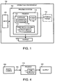
- FIG. 1 shows a block diagram of one embodiment of a printing system 100, shown for illustrative purposes only.
- Printing system 100 may be used in operating environment 102, which may be remote, independent, or included in any other printing environment.
- operating environment 102 may be remote, independent, or included in any other printing environment.
- these environments include where AC (alternating current) power may be available or may not be available, such as at the beach or on an airplane.
- printing system 100 includes printer 110 that is a single-event or limited-use printer, without a replaceable colorant(s) source, such as an inkjet ink source(s) for an inkjet printing mechanism or a toner source(s) for electro-photographic printing mechanism.
- printer 110 is intended to be used during specific occasions, such as by travelers during business trips or on vacations, or by users during parties where it may be desirable to have several printers available for guests in different locations.
- the concept "single-event" is used to convey the general idea, although it is apparent that printer 110 may be used for one or more parties, trips, vacations, etc., until the onboard ink supply is exhausted.
- printer 110 Since the printer 110 has a colorant source which is not replaceable, and since some colorants have a limited shelf life, printer 110 may be marked with an expiration use date (refer to item 205 in FIG. 2).
- Printer 110 may be pre-configured by the manufacturer to produce a maximum number of printouts or printed upon media sheets 112, for example twenty 4x6 color photo sheets. This maximum output may be determined based upon the available onboard colorant supply, and estimates as to the amount of colorant used per printed sheet. Preconfiguring for a maximum output may be useful in a bundled in sales application, where the printer is sold with the maximum amount of media sheets expected to be printed with printer 110.
- This preconfiguration may occur, for example, by storing the maximum output value, which in this example corresponds to the bundled number of media sheets, in a controller portion of the printer (for instance in a memory portion of controller 539 of FIG. 5, or controller 214 of FIG. 2).
- printer 110 may be configured with a counting routine, which monitors the amount of colorant consumed, and provides the operator with a warning when the colorant(s) are approaching empty, allowing early purchase of a new printer for use when the current printer colorant(s) are depleted.
- printer 110 is recyclable or disposable after the specific occasion is over, the use date has expired, the maximum output has been reached, or the colorants are depleted.
- printing system 100 may receive input data 104 representative of text or images to be printed. After input data 104 is received by printer 110, printer 110 prints the image on print media 112, such as paper or fabric.
- Printer 110 may include an internal print media housing 114, which receives fresh print media 112 after printer 110 prints a previous media sheet.
- Text and images may be printed on media 112 using a colorant-dispensing print engine, which in one embodiment is illustrated as one or more colorant-dispensing print cartridges, such as inkjet ink dispensing print cartridges 116, often referred to in the industry as "pens.”
- the print cartridge may include an ink container defining an ink reservoir containing ink and a printhead which dispenses ink from the reservoir.
- the inkjet printhead may be any suitable printhead that uses thermal, piezo-electric, or other ink dispensing technologies.
- print cartridge(s) 116 may be traversed over media 112 using a carriage 118 to print the image thereon to produce a print output 120.
- print cartridge(s) 116 may span the entire width of media 112 in an arrangement known as a page wide array, eliminating carriage 118.
- print cartridge(s) 116 and carriage 118 may be formed as an integral unit, so during a recycling operation of printer 110 the combined carriage/print cartridge unit may be replaced for refurbishing printer 110.
- the print engine in an inkjet context may take on many different forms, a few of which have been described here.
- the print engine may include or be complemented by additional cartridges or fluid dispensing heads, such as those which may be used to apply other compositions to be printed image.
- additional cartridges or fluid dispensing heads such as those which may be used to apply other compositions to be printed image.
- fluid over-coatings may be used often called “fixers” which may be employed to waterproof the final image or speed drying of the colorants, for example.
- fixers may be employed to waterproof the final image or speed drying of the colorants, for example.
- These additional cartridges or fluid dispensing heads may have the same configuration as the print cartridge(s) 116.
- the colorant-dispensing print engine may be configured for electrostatic or electrophotographic printing, often referred to in the industry as "laser" printing.
- the laser print cartridge 116 is typically stationary, eliminating carriage 118. While a single colorant dispensing laser print cartridge 116 is schematically illustrated in FIG. 1, it should be understood that the schematic nature of FIG. 1 may be interpreted as representing two or more laser print cartridges 116 to provide a palette of colorants for color printing.
- printer 110 may include an internal power supply 150, such as a DC (direct-current) battery power supply.
- the printer 110 may receive power from an optional external power source 152 (shown in dotted lines), which may be a DC battery or an AC power source.
- the internal power supply 150 may be supplemented or recharged by the external power source 152.
- the internal power supply 150 facilitates printer portability and operation in environments where AC power is not available, for instance in the wilderness.
- FIG. 2 shows one embodiment of an exemplary inkjet printing mechanism, here illustrated as a high-speed inkjet printer 200 incorporating an embodiment of the invention.
- printer 200 includes a chassis 202 of a rigid material, such as aluminum or alternatively, recyclable plastic or any other suitable recyclable material, surrounded by an exterior housing or casing 204.
- housing 204 is an integral and rectangular shaped member that is attached to the chassis to prevent the user from accessing the print engine.
- the housing 204 is devoid of access doors or access mechanisms that would normally permit user access to the print engine.
- This housing 204 arrangement would reduce the overall cost of the printer.
- the housing 204 can be constructed of a recyclable material which has components that may be reused in their current state, or broken down (e.g. chemically, mechanically, thermally, etc.) into a more basic composition(s) which may then be fabricated into a new product.
- casing 204 may be of a cardboard, for instance of a cellulose fiber material.
- Casing 204 may be coated with a metallic paint, or if a cardboard type of material is used, with a waterproof coating for durability and aesthetic appeal, or with other finishes, for instance those bearing images or designs.
- the casing may also bear various operator instruction indicia, easily placed on the exterior surface of casing 204 with a label, for instance displaying an expiration date label 205. Of course in other implementations, this information may be printed directly on the casing, or embossed therein.
- Printer 200 may include a media handling system 206, which may be made of a recyclable material, here shown as a mechanism through which a single sheet 112 of print media may be fed manually.
- printer 200 may include a tray for receiving a stack of fresh print media.
- Media handling system 206 may include conventional drive rollers (not shown) driven by a motor (not shown), for instance a stepper motor, which may incrementally advance media 112 through a printzone 208.
- Printer 200 shows media 112 traveling in a "straight through" path, entering on one side of the printer and exiting from the opposite side.
- media 112 may travel in a U-shaped path, entering and exiting the printer from the same side. While in printzone 208, media 112 receives ink selectively dispensed specifically from one or more print cartridges 116', illustrated here as four print cartridges dispensing cyan, yellow, magenta and black ink.
- ink refers to any type of colorant or other coating, such as a "fixer” used to waterproof or speed drying of the final image.
- the print cartridges 116' may be transported through printzone 208 by one specific embodiment of an inkjet carriage 118' which may traverse along a carriage slider or guide rod 210 supported by chassis 202.
- the media 112 may be stopped in the printzone 208 while carriage 118' scans the print cartridges 116' across the sheet for printing a swath of ink thereon. After a single scan or multiple scans, the printhead 116' is incrementally advanced to the next printing position within printzone 208.
- Carriage 118' again scans across the sheet for printing the next swath of ink. The process repeats until the entire image has been printed on media 112, at which point the printed sheet is ejected.
- the illustrated inkjet print cartridges 116' receive ink from a remote stationary ink supply (not shown) via a series of ink delivery conduits, such as flexible tubing 212.
- the print cartridges may be a portion of an integral inkjet print cartridge that carries the complete ink supply for each printhead across printzone 208, similar to commercially available disposable inkjet print cartridges, or the printheads may be coupled to separate detachable ink reservoirs, similar to "snapper" systems as known in the industry.
- the print cartridges 116' are either removably or permanently mounted to carriage 118'.
- the printhead may be a page wide array that spans the entire width of printzone 208, allowing media 112 to move continuously through printzone 208 during printing.
- printer 200 carries enough ink to last the lifetime of printer 200. That is, when ink reservoirs are depleted printer 200 may be returned to the manufacturer or its authorized agents for recycling.
- printer 200 differs from currently available inkjet printers that allow the ink supply to be replenished by an operator.
- casing 204 prohibits access to the print cartridges 116' and/or the ink supplies, when the ink supplies of print cartridges 116' are depleted, printer 200 has reached the end of its useful lifetime.
- printhead access is prohibited by omitting printhead/cartridge access doors, openings, etc., which are typically found in replaceable or refillable inkjet systems.
- casing 204 surrounds, engulfs, and protects print cartridges 116' from operator access or interference.
- one or more operator input controls such as an on/off switch (not shown) may be included on the exterior portions of the printer.
- casing 204 does not support any external buttons to limit the cost of the printer.
- insertion of print media 112 into the handling system 206 may activate printer 200 for operation, eliminating the need for an on/off switch.
- Printer 200 may also include a controller 214, illustrated schematically in FIG. 2, which receives data input 104 and any operator input if provided by the particular implementation, such as input from an on/off switch or print quality selections (e.g. draft, normal or best). Controller 214 controls operation of carriage 118 and print cartridges 116 of the print engine, in coordination with the movement of media 112 by the media handling system 206 to produce the desired output 120.
- Casing 204 may also support one or more indicator lights, such as light 216, which may indicate when printer 200 is turned on, when a print job is being received, or when the useful life of printer 200 is nearing an end, for example.
- casing 204 may support one or more digital memory card devices, such as with slots 250, 252, 254 for various digital memory card sizes, which may include compact flash, smart media or secure digital memory cards, for example.
- printer 200 may receive power from the independent internal power source 150 (FIG. 1) and/or external power source 152.
- casing 204 supports a power receptacle 218 which may be configured to receive power from electrical conductors, such as conductor 220 coupled to power source 152.
- receptacle 218 may be recessed into the printer casing 204 so the entire power supply 152 may be removably housed inside the casing.
- portions of the printer that are made with recyclable materials may be recycled by the user or the company that receives the printer after the one-time use.
- power source 152 is a battery that can be reused by the manufacturer if recycled or returned by the user. Some parts that are not damaged and that pass inspection, may be used again with minor refurbishing in the manufacture of future printers. The parts of the printer that do not pass inspection may be ground up and fed into a raw material stream for molding into new printers or for other products. Details of the recycling process for the printer and its parts are discussed below.
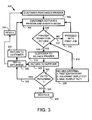
- FIG. 3 is a flow diagram a method 300, showing operation of the embodiments of FIGS. 1 and 2, as well as a business method.
- a customer may purchase printer 110 or 200.
- an activating operation 304 a customer or other operator activates printer 110, 200 and inserts print media 112, either into print media housing 114 for printer 110, or into handling system 206 for printer 200.
- the printer 110, 200 may include a controller 214 that assesses the current status of the printer in a determining operation 306 and may communicate this information to the operator.
- printer 110, 200 is proposed for a limited use, having non-replaceable colorant dispensing cartridges 116, 116'.
- return decision criteria 308 which may be stored within controller 214 for use by determining operation 306 (as indicated by double-headed arrow 310), where printer lifetime queries may be made, such as:
- the printer is not yet ready for return and a NO signal 312 is issued to proceed with a print job operation 314.
- the method may then return to the activation and media insertion operation 304, which at that point may only involve media insertion if the printer is already activated.
- a YES signal 316 is issued to alert the customer of this condition.
- This YES or "ready for return” indication signal 316 may be accomplished by changing the color of indicator light 216, for instance from a green color for "ready to print” to a red color for "ready to return.”
- the indicator light 216 may blink in a certain pattern, with the casing 204 displaying a notation correlating the blink pattern with instructions that the unit is ready for return.
- the printer 110, 200 may simply refuse to be activated or to print when in a "ready for return” state.
- the last sheet to be printed may include instructions for how to return the unit.
- the "ready for return” indication may be accompanied by instructions telling the customer to perform an optional repacking operation 318, for instance if the unit is to be shipped back to the supplier.
- the operator may be requested to return printer 110, 200 in its original shipping container necessitating the repacking operation 318.
- These instructions may be displayed on the printer casing 204, or casing 204 may display a telephone number followed by the notation "call for return instructions.” If instead, the customer is merely to deliver the unit to a return center, or a drop-off location, for instance a local retail outlet, then repacking may not be required and operation 318 may be omitted.
- the customer may proceed directly to a returning operation 320, where the printer 110, 200 may be returned to a recycle drop point, which may be the supplier.
- a returning operation 320 where the printer 110, 200 may be returned to a recycle drop point, which may be the supplier.
- the terms "customer,” and “operator” or “user,” are often used interchangeably herein, with the understanding that the customer is typically the one who purchases the printer, whereas anyone may operate or use the printer, including the customer, although the duty typically falls to the original customer or current owner to deal with returning a unit or to delegate that duty to someone else.
- the supplier or a recycling agent may perform recycling operation 326 on the returned printer 110, 200.
- printer casing 204 is constructed of a cardboard material
- the casing 204 may be designed for easy detachment from chassis 202, allowing the detached cardboard to be recycled.
- Other internal components may be designed for easy detachment from the chassis 202, and these components may then be sorted by material composition for recycling.
- media drive rollers are often constructed of an elastomeric material, such as rubber, as are several printhead servicing components, for example caps (not shown) for sealing the printheads during periods of inactivity and wipers (not shown) for cleaning the printheads.
- the disassembled drive rollers, caps and wipers may be melted down and used to form new drive rollers, caps and wipers, or other products.
- a chassis 202 made of aluminum or other metal which may similarly be melted down and used to form new aluminum stock.
- Plastic components may be similarly melted down and recycled to form new plastic components. Electronics may be recycled or upgraded for use in new printers.
- Other components such as the guide rod 210, may be formed from case hardened steel which shows very little wear over a single printer's lifetime, and may be reinstalled in another printer during operation 326.
- Designing printer 110, 200 for easy disassembly and recycling yields an environmentally friendly printer that does not clog landfills with additional waste. Many consumers prefer items made from recycled materials, so they are also advertising/sales benefits to providing a recyclable printing mechanism.
- a YES decision 328 is made, and the printer undergoes a refreshing operation 330, which may include refilling and/or refurbishing the printer or components thereof.
- various mechanical or moving components of printer 110, 200 may be replaced or upgraded, such as media drive rollers, printhead servicing components, printhead/carriage assemblies, gear assemblies, motors, etc.
- the refreshing operation 330 also provides excellent opportunity for software upgrades, or upgrades of the controller electronics.
- the colorant dispensing cartridges such as inkjet cartridges 116', may be refilled or replaced with fresh cartridges.
- the refreshed printer may be returned to the original customer for use in the activation operation 304.
- the refreshed printer may be shipped to a retailer and undergo a reselling operation 334 for use in the initial purchasing operation 302. It is apparent that in this alternate embodiment, that the original customer or more likely another customer with proceed through operations 302, 304 and 320, and if necessary, the optional repacking operation 318.
- FIG. 4 is one embodiment of a disposable inkjet printing system that incorporates an embodiment of the invention that is shown for illustrative purposes only.
- a digital camera 400 may be coupled to the printer 110 via a communication link 402, such as a docking station, electrical conductor, an optical interface, an infrared port, or a radio wave interface, to name a few.
- An operator may print on media 112 a multiple copy of an individual photograph, or may use the system to determine the quality or composition of the photograph, or print one or more copies of the number of photographs selected by the operator to produce output 120.
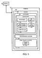
- FIG. 5 is an embodiment of an inkjet printing system that incorporates an embodiment of the invention that is shown for illustrative purposes only.
- the printer 110 may be a recyclable integrated printer with elements that may be replaced, maintained, refilled or refurbished in refreshing operation 330 (see FIG. 3), or recycled in operation 326 (see FIG. 3) by a supply source 500, which may be an agent or manufacturer.
- the printer 110 may include a carriage guide or slider rod 510 that slidably supports a carriage 520 for scanning across media 112 when in a printzone, such as printzone 208 (see FIG. 2).
- the carriage 520 may transport one or more ink dispensing print cartridges 530 across the printzone for printing a selected image on print media 112.
- the print cartridge 530 may be detachably mounted to carriage 520, or the print cartridge 530 may be permanently attached to carriage 520 to form a carriage/cartridge subassembly or subsystem.
- the carriage/cartridge subsystem may be an integrated unit including a printhead 532, an ink supply 534, an electrical interconnect 536, a pen driver 538, and carriage 530 a single unit.
- the ink supply 534 and printhead 532 are integral and the operator is not given permission to separate the two.
- the printhead 532 is replaced by the refurbisher in the refreshing operation 330 (see FIG. 3).
- the supplier chooses to conduct the recycling operation 326 (see FIG. 3)
- these components are separated for recycling.
- the printer 110 is returned to supply source 500 shown in FIG. 5.
- the slider 510 may be a rod upon which the cartridge/carriage subsystem rides while scanning across media 112 in the printzone.
- a controller 539 which may be an ASIC (application-specific integrated circuit) or other control system, may have a system for collecting data on the use of the printer 110, thereby monitoring the useful life of the printer. This embodiment may also facilitate efficient maintenance, which may extend the life of the printer.
- the printer 110 When the printer 110 is nearing the end of its pre-configured life, for instance when the determining operation 306 (see FIG. 3) finds the printer is ready for return, an operator is alerted by YES signal 316 to conduct the returning operation 320, and optionally the repacking operation 318.
- the controller 539 is a replaceable controller that allows for easy hardware/software upgrades during the refreshing operation 330 (see FIG. 3).
- the printer 110 may include a data transmission system 540, discussed in further detail below.
- Print media 112 may be housed in the print media housing 114. As mentioned above with respect to FIG. 2, alternatively media 112 may be manually fed to handling system 206.
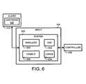
- FIG. 6 shows a detailed block diagram of one embodiment of data transmission system 540 of FIG. 5.
- one type of transmission system may include a wireless system 620 which may communicate between the printer controller 539 and the printer cartridge 530.
- transmission system 540 may receive input 104 through a conventional flex cable (not shown).
- the transmission system may comprise a wireless data transmission system 620, such as one based on Bluetooth technology, infrared communication technology, optic communication technology, or other suitable wireless data transmission technique.
- Data communication in one embodiment may be accomplished using USB (universal serial bus) port 622, for instance when coupling printer 110, 200 to other input devices, such as a digital camera or PC (personal computer).
- communication may be made using memory storage devices 624, such as smart cards, camera cards, compact flash, etc.
- data communication may be accomplished through a docking cradle 626, such as a camera cradle integrated into the printer casing 204 as a docking station.
- the cradle 626 may be configured to interface universally with a variety of different types of cameras.
- the cradle 626 may be configured for a specific camera 400 which may be bundled with printer 110, 200 for sale at the original point-of-sale.
- Data may be transmitted through printer controller 539 to cartridge 530. This data may be linked through the slider 520 to carriage 520 then to cartridge 530, eliminating use of the conventional flex cable.
Landscapes
- Accessory Devices And Overall Control Thereof (AREA)
- Ink Jet (AREA)
Applications Claiming Priority (2)
| Application Number | Priority Date | Filing Date | Title |
|---|---|---|---|
| US10/638,698 US20050030554A1 (en) | 2003-08-09 | 2003-08-09 | Recyclable printing mechanism and related method |
| US638698 | 2003-08-09 |
Publications (2)
| Publication Number | Publication Date |
|---|---|
| EP1506876A2 true EP1506876A2 (fr) | 2005-02-16 |
| EP1506876A3 EP1506876A3 (fr) | 2006-07-19 |
Family
ID=33565220
Family Applications (1)
| Application Number | Title | Priority Date | Filing Date |
|---|---|---|---|
| EP04003525A Withdrawn EP1506876A3 (fr) | 2003-08-09 | 2004-02-17 | Dispositif recyclable d'impression et procédé associé |
Country Status (2)
| Country | Link |
|---|---|
| US (1) | US20050030554A1 (fr) |
| EP (1) | EP1506876A3 (fr) |
Cited By (1)
| Publication number | Priority date | Publication date | Assignee | Title |
|---|---|---|---|---|
| EP2146255A1 (fr) * | 2008-07-18 | 2010-01-20 | Ricoh Company, Ltd. | Système d'aide de recyclage, appareil électronique, et procédé d'aide de recyclage |
Families Citing this family (41)
| Publication number | Priority date | Publication date | Assignee | Title |
|---|---|---|---|---|
| US6786420B1 (en) | 1997-07-15 | 2004-09-07 | Silverbrook Research Pty. Ltd. | Data distribution mechanism in the form of ink dots on cards |
| US6618117B2 (en) | 1997-07-12 | 2003-09-09 | Silverbrook Research Pty Ltd | Image sensing apparatus including a microcontroller |
| US7110024B1 (en) | 1997-07-15 | 2006-09-19 | Silverbrook Research Pty Ltd | Digital camera system having motion deblurring means |
| US20040119829A1 (en) | 1997-07-15 | 2004-06-24 | Silverbrook Research Pty Ltd | Printhead assembly for a print on demand digital camera system |
| US6879341B1 (en) | 1997-07-15 | 2005-04-12 | Silverbrook Research Pty Ltd | Digital camera system containing a VLIW vector processor |
| US6624848B1 (en) | 1997-07-15 | 2003-09-23 | Silverbrook Research Pty Ltd | Cascading image modification using multiple digital cameras incorporating image processing |
| US6690419B1 (en) | 1997-07-15 | 2004-02-10 | Silverbrook Research Pty Ltd | Utilising eye detection methods for image processing in a digital image camera |
| AUPP702098A0 (en) | 1998-11-09 | 1998-12-03 | Silverbrook Research Pty Ltd | Image creation method and apparatus (ART73) |
| US7236271B2 (en) * | 1998-11-09 | 2007-06-26 | Silverbrook Research Pty Ltd | Mobile telecommunication device with printhead and media drive |
| US8138413B2 (en) * | 2006-04-13 | 2012-03-20 | Daniel Luch | Collector grid and interconnect structures for photovoltaic arrays and modules |
| AUPQ439299A0 (en) | 1999-12-01 | 1999-12-23 | Silverbrook Research Pty Ltd | Interface system |
| AUPQ291299A0 (en) * | 1999-09-17 | 1999-10-07 | Silverbrook Research Pty Ltd | A self mapping surface and related applications |
| AUPQ056099A0 (en) * | 1999-05-25 | 1999-06-17 | Silverbrook Research Pty Ltd | A method and apparatus (pprint01) |
| US20050212830A1 (en) * | 1999-09-17 | 2005-09-29 | Silverbrook Research Pty Ltd | Method of accessing a connection address using a mobile device with a sensing means |
| US7999964B2 (en) * | 1999-12-01 | 2011-08-16 | Silverbrook Research Pty Ltd | Printing on pre-tagged media |
| SG152904A1 (en) | 2000-10-20 | 2009-06-29 | Silverbrook Res Pty Ltd | Cartridge for an electronic pen |
| US7740347B2 (en) * | 2002-12-02 | 2010-06-22 | Silverbrook Research Pty Ltd | Ink usage tracking in a cartridge for a mobile device |
| US7991432B2 (en) * | 2003-04-07 | 2011-08-02 | Silverbrook Research Pty Ltd | Method of printing a voucher based on geographical location |
| US7824031B2 (en) * | 2005-05-09 | 2010-11-02 | Silverbrook Research Pty Ltd | Print cartridge with friction driven media feed shaft |
| US7753517B2 (en) * | 2005-05-09 | 2010-07-13 | Silverbrook Research Pty Ltd | Printhead with an optical sensor for receiving print data |
| US7466993B2 (en) * | 2005-05-09 | 2008-12-16 | Silverbrook Research Pty Ltd | Mobile telecommunications device dual media coding detectors |
| US7607774B2 (en) * | 2005-05-09 | 2009-10-27 | Silverbrook Research Pty Ltd | Mobile telecommunication device with a printhead and single media feed roller |
| US7517046B2 (en) * | 2005-05-09 | 2009-04-14 | Silverbrook Research Pty Ltd | Mobile telecommunications device with printhead capper that is held in uncapped position by media |
| US20060252456A1 (en) * | 2005-05-09 | 2006-11-09 | Silverbrook Research Pty Ltd | Mobile device with printhead for receiving data via modulate light signal |
| US7697159B2 (en) * | 2005-05-09 | 2010-04-13 | Silverbrook Research Pty Ltd | Method of using a mobile device to determine movement of a print medium relative to the mobile device |
| US8104889B2 (en) * | 2005-05-09 | 2012-01-31 | Silverbrook Research Pty Ltd | Print medium with lateral data track used in lateral registration |
| US7447908B2 (en) | 2005-05-09 | 2008-11-04 | Silverbrook Research Pty Ltd | Method of authenticating a print medium offline |
| US7284921B2 (en) * | 2005-05-09 | 2007-10-23 | Silverbrook Research Pty Ltd | Mobile device with first and second optical pathways |
| US8061793B2 (en) | 2005-05-09 | 2011-11-22 | Silverbrook Research Pty Ltd | Mobile device that commences printing before reading all of the first coded data on a print medium |
| US7392950B2 (en) * | 2005-05-09 | 2008-07-01 | Silverbrook Research Pty Ltd | Print medium with coded data in two formats, information in one format being indicative of information in the other format |
| US7566182B2 (en) * | 2005-05-09 | 2009-07-28 | Silverbrook Research Pty Ltd | Printhead that uses data track for print registration on print medium |
| US7645022B2 (en) * | 2005-05-09 | 2010-01-12 | Silverbrook Research Pty Ltd | Mobile telecommunication device with a printhead, a capper and a locking mechanism for holding the capper in an uncapped position during printing |
| US7558962B2 (en) | 2005-05-09 | 2009-07-07 | Silverbrook Research Pty Ltd | Method of authenticating a print medium online |
| US7465047B2 (en) | 2005-05-09 | 2008-12-16 | Silverbrook Research Pty Ltd | Mobile telecommunication device with a printhead and media sheet position sensor |
| US7726764B2 (en) * | 2005-05-09 | 2010-06-01 | Silverbrook Research Pty Ltd | Method of using a mobile device to determine a position of a print medium configured to be printed on by the mobile device |
| US20120050417A1 (en) * | 2007-04-20 | 2012-03-01 | David Olsen | Printing device having supply of colorant that is non-refillable and at least substantially non-removable from end user perspective |
| US20080259112A1 (en) * | 2007-04-20 | 2008-10-23 | David Olsen | Printing device having supply of colorant that is non-refillable and at least substantially non-removable from end user perspective |
| WO2013019186A1 (fr) * | 2011-07-29 | 2013-02-07 | Hewlett-Packard Development Company, L.P. | Imprimante |
| DK3226075T3 (en) * | 2011-08-19 | 2018-12-10 | Hewlett Packard Development Co | TONER CONTAINER |
| JP6269932B2 (ja) * | 2013-12-18 | 2018-01-31 | セイコーエプソン株式会社 | 記録装置 |
| US11868955B2 (en) * | 2021-05-18 | 2024-01-09 | Hewlett-Packard Development Company, L.P. | Shipping print components |
Family Cites Families (7)
| Publication number | Priority date | Publication date | Assignee | Title |
|---|---|---|---|---|
| JPH0233310B2 (ja) * | 1983-11-15 | 1990-07-26 | Tokyo Electric Co Ltd | Injisochi |
| US4998213A (en) * | 1987-06-15 | 1991-03-05 | Fuji Xerox Co., Ltd. | Recording apparatus |
| GB2315488B (en) * | 1995-05-27 | 1999-07-21 | Ricoh Kk | Product including parts which can be recycled |
| US5808635A (en) * | 1996-05-06 | 1998-09-15 | Xerox Corporation | Multiple die assembly printbar with die spacing less than an active print length |
| AUPP089597A0 (en) * | 1997-12-12 | 1998-01-08 | Silverbrook Research Pty Ltd | An image creation method and apparatus (IR01) |
| US6203224B1 (en) * | 2000-01-28 | 2001-03-20 | Eastman Kodak Company | Print engine chassis for supporting a vacuum imaging drum |
| US6476843B2 (en) * | 2000-12-28 | 2002-11-05 | Eastman Kodak Company | Reinforced sheet metal frame incorporating print engine chassis |
-
2003
- 2003-08-09 US US10/638,698 patent/US20050030554A1/en not_active Abandoned
-
2004
- 2004-02-17 EP EP04003525A patent/EP1506876A3/fr not_active Withdrawn
Cited By (1)
| Publication number | Priority date | Publication date | Assignee | Title |
|---|---|---|---|---|
| EP2146255A1 (fr) * | 2008-07-18 | 2010-01-20 | Ricoh Company, Ltd. | Système d'aide de recyclage, appareil électronique, et procédé d'aide de recyclage |
Also Published As
| Publication number | Publication date |
|---|---|
| EP1506876A3 (fr) | 2006-07-19 |
| US20050030554A1 (en) | 2005-02-10 |
Similar Documents
| Publication | Publication Date | Title |
|---|---|---|
| EP1506876A2 (fr) | Dispositif recyclable d'impression et procédé associé | |
| JP4650523B2 (ja) | 電子装置、消耗品カートリッジ、交換部品、及び利用度合を報知する方法 | |
| US6663304B2 (en) | Simultaneously printing information on two sides of print media | |
| US6233408B1 (en) | Image forming device with token printing capabilities | |
| EP1270226A2 (fr) | Procédé et dispositif pour calculer la quantité d'encre consommée, imprimante à jet d'encre avec le dispositif, système pour calculer les coûts d'impression, et système pour gérer l'alimentation en encre | |
| EP1170133B1 (fr) | Dispositif et méthode de diagnostic d'imprimante et support d'enregistrement lisible par ordinateur comportant un programme avec une fonction de diagnostic d'imprimante | |
| US20110188070A1 (en) | Detection and replacement of consumable components of computer peripherals | |
| US20030043401A1 (en) | System and method for estimating ink usage of a print job | |
| JP2002215368A (ja) | 課金を行なうプリンタシステムおよび料金の見積を行なう印刷制御装置 | |
| EP2017679B1 (fr) | Dispositif, appareil de support de maintenance et système de support | |
| JP2004133938A (ja) | プリントプレビューでの消耗品の利用可能性 | |
| JP2004358734A (ja) | 画像形成装置、プログラムおよび記録媒体 | |
| JP2009043248A (ja) | 保守装置、保守方法、デバイス、保守システム、およびコンピュータプログラム | |
| JP2005111707A (ja) | プリント装置 | |
| JP2003011469A (ja) | 消耗品ユニット及びそれを用いた画像形成装置 | |
| JP2004240110A (ja) | 印刷装置 | |
| US7063399B2 (en) | Imaging apparatus and method for facilitating printing | |
| JP2026009603A (ja) | 消費装置、およびプログラム | |
| JP2007304650A (ja) | 印刷システム | |
| JP2023019438A (ja) | 印刷システム | |
| JP2002370427A (ja) | 着色材供給管理システム | |
| JP4349838B2 (ja) | 画像形成装置 | |
| JP2003196068A (ja) | 消耗品管理システム及び消耗品管理方法と印刷制御装置 | |
| US20040155925A1 (en) | Printing apparatus | |
| JP2024027560A (ja) | 提供システム、提供方法、及び管理装置 |
Legal Events
| Date | Code | Title | Description |
|---|---|---|---|
| PUAI | Public reference made under article 153(3) epc to a published international application that has entered the european phase |
Free format text: ORIGINAL CODE: 0009012 |
|
| AK | Designated contracting states |
Kind code of ref document: A2 Designated state(s): AT BE BG CH CY CZ DE DK EE ES FI FR GB GR HU IE IT LI LU MC NL PT RO SE SI SK TR |
|
| AX | Request for extension of the european patent |
Extension state: AL LT LV MK |
|
| 17P | Request for examination filed |
Effective date: 20060301 |
|
| PUAL | Search report despatched |
Free format text: ORIGINAL CODE: 0009013 |
|
| AK | Designated contracting states |
Kind code of ref document: A3 Designated state(s): AT BE BG CH CY CZ DE DK EE ES FI FR GB GR HU IE IT LI LU MC NL PT RO SE SI SK TR |
|
| AX | Request for extension of the european patent |
Extension state: AL LT LV MK |
|
| AKX | Designation fees paid |
Designated state(s): DE FR GB |
|
| STAA | Information on the status of an ep patent application or granted ep patent |
Free format text: STATUS: THE APPLICATION IS DEEMED TO BE WITHDRAWN |
|
| 18D | Application deemed to be withdrawn |
Effective date: 20070901 |