EP1507080A1 - Tuyère convergente divergente de turboréacteur - Google Patents
Tuyère convergente divergente de turboréacteur Download PDFInfo
- Publication number
- EP1507080A1 EP1507080A1 EP04291938A EP04291938A EP1507080A1 EP 1507080 A1 EP1507080 A1 EP 1507080A1 EP 04291938 A EP04291938 A EP 04291938A EP 04291938 A EP04291938 A EP 04291938A EP 1507080 A1 EP1507080 A1 EP 1507080A1
- Authority
- EP
- European Patent Office
- Prior art keywords
- flaps
- wall
- walls
- nozzle
- holes
- Prior art date
- Legal status (The legal status is an assumption and is not a legal conclusion. Google has not performed a legal analysis and makes no representation as to the accuracy of the status listed.)
- Granted
Links
- 238000001816 cooling Methods 0.000 claims abstract description 21
- 125000006850 spacer group Chemical group 0.000 claims description 15
- 239000007789 gas Substances 0.000 description 7
- 238000010438 heat treatment Methods 0.000 description 4
- 230000001681 protective effect Effects 0.000 description 4
- 238000011144 upstream manufacturing Methods 0.000 description 4
- 238000006073 displacement reaction Methods 0.000 description 1
- 238000000926 separation method Methods 0.000 description 1
- 238000005476 soldering Methods 0.000 description 1
- 238000003466 welding Methods 0.000 description 1
Images


Classifications
-
- F—MECHANICAL ENGINEERING; LIGHTING; HEATING; WEAPONS; BLASTING
- F02—COMBUSTION ENGINES; HOT-GAS OR COMBUSTION-PRODUCT ENGINE PLANTS
- F02K—JET-PROPULSION PLANTS
- F02K1/00—Plants characterised by the form or arrangement of the jet pipe or nozzle; Jet pipes or nozzles peculiar thereto
- F02K1/06—Varying effective area of jet pipe or nozzle
- F02K1/12—Varying effective area of jet pipe or nozzle by means of pivoted flaps
- F02K1/1223—Varying effective area of jet pipe or nozzle by means of pivoted flaps of two series of flaps, the upstream series having its flaps hinged at their upstream ends on a fixed structure and the downstream series having its flaps hinged at their upstream ends on the downstream ends of the flaps of the upstream series
-
- F—MECHANICAL ENGINEERING; LIGHTING; HEATING; WEAPONS; BLASTING
- F02—COMBUSTION ENGINES; HOT-GAS OR COMBUSTION-PRODUCT ENGINE PLANTS
- F02K—JET-PROPULSION PLANTS
- F02K1/00—Plants characterised by the form or arrangement of the jet pipe or nozzle; Jet pipes or nozzles peculiar thereto
- F02K1/78—Other construction of jet pipes
- F02K1/82—Jet pipe walls, e.g. liners
- F02K1/822—Heat insulating structures or liners, cooling arrangements, e.g. post combustion liners; Infrared radiation suppressors
-
- Y—GENERAL TAGGING OF NEW TECHNOLOGICAL DEVELOPMENTS; GENERAL TAGGING OF CROSS-SECTIONAL TECHNOLOGIES SPANNING OVER SEVERAL SECTIONS OF THE IPC; TECHNICAL SUBJECTS COVERED BY FORMER USPC CROSS-REFERENCE ART COLLECTIONS [XRACs] AND DIGESTS
- Y02—TECHNOLOGIES OR APPLICATIONS FOR MITIGATION OR ADAPTATION AGAINST CLIMATE CHANGE
- Y02T—CLIMATE CHANGE MITIGATION TECHNOLOGIES RELATED TO TRANSPORTATION
- Y02T50/00—Aeronautics or air transport
- Y02T50/60—Efficient propulsion technologies, e.g. for aircraft
Definitions
- the present invention relates to a convergent nozzle divergent turbojet.
- Such convergent divergent nozzles hereinafter referred to as CV-DV nozzles, generally equip turbojet engines of military supersonic aircraft.
- FIG. 1 schematically represents a CV-DV nozzle 1 of known type.
- This X-axis nozzle comprises a first ring of convergent flaps 2 and a second crown of diverging flaps 4.
- the shutters 2a, 4a, follower flaps 2b, 4b are the shutters 2a, 4a, follower flaps 2b, 4b.
- the controlled shutters 2a, 4a are connected to a mechanism of command 5 which allows to move them.
- This control mechanism is generally consists of levers, rods, clevises, or a ring, pebble and cams. Moving shutters ordered 2a, 4a makes it possible to modify the opening of the nozzle 1 as a function of the flight conditions, and for this reason, we speak of nozzle section variable.
- the follower flaps 2b, 4b are interposed between the flaps ordered and supported on both sides at their edges lateral, on the radially inner face of the controlled shutters 2a, 4a.
- the follower flaps are therefore not connected to a mechanism of command, they are content to follow the shutters ordered 2a, 4a.
- the radial direction is defined in this memoir as being the direction perpendicular to the X axis of the nozzle, and the inner face of an element as being the face of the element opposite the X axis.
- the nozzle 1 is crossed by a stream of hot gases from the chamber of afterburner of the turbojet.
- the control mechanism 5 of the controlled shutters 2a, 4a by varying the opening of the nozzle, allows to increase or decrease the speed of escape of the stream gaseous at the outlet of the nozzle.
- the temperatures of the flow of hot gases passing through the nozzle CV-DVs are generally very high, so that several cooling were developed to limit the heating of the faces radially internal flaps of the nozzle.
- the divergent flaps ordered are not supplied with cooling air and therefore have no multiperforations, only means to inject air at the neck (the smallest section) of the nozzle are provided to cool these shutters.
- such means are not sufficient to properly cool the controlled divergent flaps, especially in the regions of these shutters remote from said pass.
- the invention proposes to improve the cooling of the shutters controlled from a CV-DV nozzle, especially when flaps Controlled divergents are not themselves supplied with air from cooling.
- the subject of the invention is a CV-DV nozzle turbojet engine comprising controlled divergent flaps, flaps diverging followers interposed between the shutters ordered, and means for supplying cooling air to the diverging flaps followers, the latter having a box structure with a wall radially internal, and a radially outer wall.
- said follower divergent flaps also have openings side sections for delivering cooling air to the internal face of said controlled divergent flaps, to cool these last.
- the invention thus uses a part of the cooling air which feeds the divergent follower flaps to cool the inner face of the divergent shutters ordered. This is particularly useful when the divergent shutters ordered are not themselves supplied with air cooling.
- Limiting the heating of the divergent flaps ordered allows on the one hand to increase the life of the parts of these components, and secondly, in the context of military operations, to improve the infrared discretion of the nozzle of the aircraft.
- the outer and inner walls of the nozzle are fitted into each other at the level of their lateral ends, while keeping the possibility of slide between them.
- each follower flap must have torsional flexibility, so that its lateral edges remain in contact with the internal surface of the two shutters ordered around it, even when there is a slight discrepancy between these two components, which is becoming common with the wear and tear of control of these shutters. This flexibility in torsion is improved thanks to the sliding possibilities of the outer and inner walls between them.
- the lateral ends of the outer walls and internal are curved.
- the outer and inner walls of the nozzle each have holes on the along their lateral ends.
- the holes of one of the walls are located next to the holes of the other wall when these walls are interlocked one in the other, and thus form said lateral openings.
- the holes of one of the walls have a section greater than that of the holes in the other wall, so that the hole more small section still leads inside the hole of bigger regardless of the position of the internal and external walls between they. This ensures the presence of lateral openings when the walls internal and external slide between them, following phenomena of expansion or torsion of the shutter.
- the internal and external walls of the divergent flaps followers present each at least one notch formed on their lateral periphery, opening into one of said holes.
- Such a notch makes it possible to reduce the constraints within the shutter, related to the expansion of the walls, or to the twist of the shutter. Moreover, as each notch leads to inside one of the said holes, the appearance of cracks at the end of the notch is avoided.
- each follower divergent flap further comprises a spacer, located between its inner wall and its outer wall, in the plane of symmetry of the flap. This spacer strengthens the structure of the shutter and allows it to keep its shape even when the pressures exerted on its inner wall by the flow of hot gas passing through the nozzle, are high.
- each diverter flap follower further comprises a slideway secured to the outer wall of said flap, and in that the section of said spacer has the general shape of an I, the base of the spacer being attached to the inner wall said flap, and its upper part being able to slide in said slide.
- This particular structure allows the movement of the wall internal flap relative to its outer wall. We thus succeed in strengthen the structure of the component while maintaining the flexibility of this last.
- the wall radially internal of the diverging follower flaps furthermore presents perforations likely to let out the cooling air. This creates a protective air film on the surface of the shutter.
- Controlled divergents are not supplied with cooling air, and therefore only cooled through the side openings present on the follower flaps.
- This embodiment greatly simplifies the structure of the CV-DV nozzle because it makes it possible to produce divergent flaps ordered having no hollow structure, in box, necessary to the passage of cooling air. On the contrary, we can achieve shutters having a so-called simple skin structure, that is to say single wall. he it is easy to connect this type of controlled component to command that direct it.
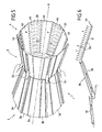
- the general structure of the nozzle according to the invention is similar to that of the nozzle shown in FIG. 1, and previously described.
- the nozzle 1 comprises convergent flaps 2 and flaps divergent 4.
- the divergent components 4 there are Controlled diverging 4a and follower diverging flaps 4b.
- Each follower divergent flap 4b builds on the two divergent flaps adjacent control in an area at its edges side.
- Controlled divergent flaps 4a are articulated to their upstream end on the downstream ends of the convergent flaps 2a, and the follower divergent flaps 4b are also articulated at their upstream end on the downstream ends of the shutters convergent followers 2b.
- Each component diverges follower 4b presents a structure in box, and a substantially trapezoidal cross section, represented in FIG. 2, with a radially inner wall 6, and a wall radially external 8.
- the lateral ends 8a of the outer wall 8 and the lateral ends 6a of the inner wall 6 are curved and the curvatures of the lateral ends 6a and 8a are such that the walls internal and external 6 and 8 can be inserted into one another, the ends of the inner wall 6a covering those of the outer wall 8.
- the lateral ends 6a of the inner wall 6 form slide for the lateral ends 8a of the outer wall 8, of so that these walls can slide between them in the axial direction.
- the lateral edges of the flap 4b are therefore formed by the covering the lateral ends of the inner and outer walls 6 and 8.
- the follower flap 4b is also provided with several spacers 20 distributed regularly along the shutter and located between the inner wall 6 and the outer wall 8, in the plane of symmetry of the flap.
- the spacer 20 consists of a straight core assembled to a base and an upper part perpendicular to the soul, the section of the spacer having the general shape of an I.
- the base of the spacer is fixed, by welding, soldering, or any other suitable means of fixation, on the inner wall 6 of the flap.
- the upper part of the spacer 20 is composed of two branches 20a which deviate on each side of the soul of the spacer 20, perpendicular to the direction of this core.
- an axial slide 22 in which is practiced a slot 24 extending along the plane of symmetry of the shutter.
- the width of the slot 24 is greater than the thickness of the core of the spacer 20, and the spacer 20 can slide into the slide 22 in the direction of the slot.
- the branches 20a of the spacer 20 extend between the slide 22 and the outer wall 8, and are able to come to an end against one or the other of these parts to limit the approximation or the separation of the inner and outer walls 6 and 8, by which the shape of the shutter is improved.
- the internal walls and 6, 8 each have along their lateral ends 6a, 8a holes 12, 14, arranged at regular intervals.
- the holes 14 of the outer wall 8 are located opposite the holes 12 of the wall 6, and thus form lateral openings in the structure of the follower flap 4b.
- the holes 12 of the outer wall 8 are of oblong shape and have a section greater than that of the circular holes 14 of the wall 6.
- the size and shape of the oblong holes 12 are determined for circular holes 14 are never hidden, even when the outer 8 and inner 6 walls expand differently and / or when the follower lug 4b is twisted causing displacement of the two walls 6 and 8, one relative to the other.
- the inner and outer walls 6, 8 are respectively provided with notches 16 and 18 at regular intervals along their lateral ends 6a and 8a. These notches 16 and 18 start on the edge of the lateral ends 6a, 8a, extend perpendicular to this edge and open at the holes 12 and 14 practiced in each of the walls 6 and 8.
- the inner wall 6 of the shutters followers 4b has many perforations 26 in its part Central. We talk about multiperforations.
- Cooling air flaps diverging followers 4b comes from a manifold, not shown, placed upstream of the nozzle, by relative to the flow direction of the hot gases passing through it.
- the air taken is routed to the follower divergent flaps 4b, as shown schematically figure 6, passing under a protective shirt 30 of the turbojet engine upstream of the nozzle, and by a piping system 32. Then the air circulates inside the box structure of the divergent flaps 4b, and out through the perforations 26 and the lateral openings 12, 14 of said flaps 4b.
- the cold air exiting through the lateral openings 12, 14 according to the arrows F ' is in turn directed circumferentially towards the inner face controlled divergent flaps 4a and allows first cool this last by impact. Then this cold air creates a protective film on the inner face of the controlled divergent flaps 4a, which allows to mitigate the exchange of heat between the hot gases passing through the nozzle and these flaps 4a, whereby they limit their heating.
Landscapes
- Engineering & Computer Science (AREA)
- Chemical & Material Sciences (AREA)
- Combustion & Propulsion (AREA)
- Mechanical Engineering (AREA)
- General Engineering & Computer Science (AREA)
- Turbine Rotor Nozzle Sealing (AREA)
- Jet Pumps And Other Pumps (AREA)
- Nozzles (AREA)
- Physical Or Chemical Processes And Apparatus (AREA)
- Cyclones (AREA)
- Structures Of Non-Positive Displacement Pumps (AREA)
Abstract
Description
- la figure 1 est une vue en perspective d'une tuyère CV-DV de l'art antérieur ;
- la figure 2 est une vue en coupe transversale d'un volet divergent suiveur d'une tuyère selon l'invention ;
- les figures 3a et 3b sont des vues de détails des ouvertures latérales du volet de la figure 2 ; et
- la figure 4 représente une partie des volets divergents d'une tuyère selon l'invention, vue de l'intérieur de la tuyère ;
- la figure 5 est une vue en perspective d'une tuyère CV-DV selon l'invention ; et
- la figure 6 représente schématiquement, en demi-coupe axiale, une tuyère CV-DV selon l'invention.
Claims (11)
- Tuyère convergente-divergente de turboréacteur comprenant des volets divergents commandés (4a), des volets divergents suiveurs (4b) intercalés entre les volets commandés, et des moyens (32) pour alimenter en air de refroidissement les volets divergents suiveurs (4b), lesdits volets divergents suiveurs (4b) ayant une structure en caisson avec une paroi radialement interne (6), et une paroi radialement externe (8), caractérisée en ce que lesdits volets divergents suiveurs présentent des ouvertures latérales destinées à délivrer de l'air de refroidissement en direction de la face interne desdits volets divergents commandés (4a), pour refroidir ces derniers.
- Tuyère selon la revendication 1, caractérisée en ce que les parois externe (8) et interne (6) sont emboítées l'une dans l'autre au niveau de leurs extrémités latérales, tout en gardant la possibilité de coulisser entre elles.
- Tuyère selon la revendication 2, caractérisée en ce que lesdites extrémités latérales des parois externe (8) et interne (6) sont courbes.
- Tuyère selon l'une quelconque des revendications 1 à 3, caractérisée en ce que les parois externe (8) et interne (6) présentent chacune des trous (12, 14) le long de leurs extrémités latérales, et en ce que les trous (12) de l'une des parois (8) se situent en regard des trous (14) de l'autre paroi (6) lorsque ces parois sont emboítées l'une dans l'autre, par quoi lesdites ouvertures latérales sont formées.
- Tuyère selon la revendication 4, caractérisée en ce que les trous (12) de l'une des parois (8) ont une section supérieure à celle des trous (14) de l'autre paroi (6).
- Tuyère selon la revendication 4 ou 5, caractérisée en ce que les trous (12) de l'une des parois (8) sont de forme oblongue, tandis que les trous (14) de l'autre paroi (6) sont de forme circulaire.
- Tuyère selon l'une quelconque des revendications 4 à 6, caractérisée en ce que les parois externe (8) et interne (6) présentent chacune au moins une encoche (16, 18) ménagée sur leur périphérie latérale, débouchant à l'intérieur de l'un desdits trous (12, 14).
- Tuyère selon l'une quelconque des revendications précédentes, caractérisée en ce que chaque volet divergent suiveur (4b) comprend en outre, une entretoise (20), située entre sa paroi interne (6) et sa paroi externe (8), dans le plan de symétrie dudit volet.
- Tuyère selon la revendication 8, caractérisée en ce que chaque volet divergent suiveur (4b) comprend en outre une glissière (22) fixée à la paroi externe (8) dudit volet, et en ce que ladite entretoise (20) a la forme générale d'un I, sa base étant fixée à la paroi interne (6) dudit volet, et sa partie supérieure étant apte à glisser dans ladite glissière (22).
- Tuyère selon l'une quelconque des revendications précédentes, caractérisée en ce que la paroi radialement interne (6) des volets divergents suiveurs (4b) présente en outre des perforations (26) susceptibles de laisser s'échapper l'air de refroidissement.
- Tuyère selon l'une quelconque des revendications précédentes, caractérisée en ce que lesdits volets divergents commandés (4a) ne sont pas alimentés en air de refroidissement.
Applications Claiming Priority (2)
| Application Number | Priority Date | Filing Date | Title |
|---|---|---|---|
| FR0309854 | 2003-08-12 | ||
| FR0309854A FR2858833B1 (fr) | 2003-08-12 | 2003-08-12 | Tuyere convergente divergente du turboreacteur |
Publications (2)
| Publication Number | Publication Date |
|---|---|
| EP1507080A1 true EP1507080A1 (fr) | 2005-02-16 |
| EP1507080B1 EP1507080B1 (fr) | 2006-03-22 |
Family
ID=33561163
Family Applications (1)
| Application Number | Title | Priority Date | Filing Date |
|---|---|---|---|
| EP04291938A Expired - Lifetime EP1507080B1 (fr) | 2003-08-12 | 2004-07-29 | Tuyère convergente divergente de turboréacteur |
Country Status (9)
| Country | Link |
|---|---|
| US (1) | US6993914B2 (fr) |
| EP (1) | EP1507080B1 (fr) |
| JP (1) | JP2005061405A (fr) |
| AT (1) | ATE321201T1 (fr) |
| CA (1) | CA2478781A1 (fr) |
| DE (1) | DE602004000528T2 (fr) |
| ES (1) | ES2260734T3 (fr) |
| FR (1) | FR2858833B1 (fr) |
| RU (1) | RU2346175C2 (fr) |
Cited By (2)
| Publication number | Priority date | Publication date | Assignee | Title |
|---|---|---|---|---|
| EP1750001A3 (fr) * | 2005-08-02 | 2008-06-04 | Rolls-Royce plc | Tuyère de propulsion pour un moteur à turbine à gaz |
| FR2945580A1 (fr) * | 2009-05-15 | 2010-11-19 | Snecma | Chambre de combustion de moteur pour un vehicule capable de se deplacer dans l'air ou dans l'espace et son procede de fabrication. |
Families Citing this family (19)
| Publication number | Priority date | Publication date | Assignee | Title |
|---|---|---|---|---|
| US7458221B1 (en) * | 2003-10-23 | 2008-12-02 | The United States Of America As Represented By The Administrator Of The National Aeronautics And Space Administration | Variable area nozzle including a plurality of convexly vanes with a crowned contour, in a vane to vane sealing arrangement and with nonuniform lengths |
| US7377099B2 (en) * | 2005-05-27 | 2008-05-27 | United Technologies Corporation | System and method for cooling lateral edge regions of a divergent seal of an axisymmetric nozzle |
| US7762078B2 (en) * | 2006-09-13 | 2010-07-27 | Aerojet-General Corporation | Nozzle with temperature-responsive throat diameter |
| US8205454B2 (en) * | 2007-02-06 | 2012-06-26 | United Technologies Corporation | Convergent divergent nozzle with edge cooled divergent seals |
| US8047004B2 (en) * | 2008-02-12 | 2011-11-01 | The Boeing Company | Stave and ring CMC nozzle |
| US8166752B2 (en) * | 2008-11-26 | 2012-05-01 | GM Global Technology Operations LLC | Apparatus and method for cooling an exhaust gas |
| US20120145808A1 (en) * | 2010-12-14 | 2012-06-14 | The Boeing Company | Method and apparatus for variable exhaust nozzle exit area |
| US10060389B2 (en) * | 2010-12-14 | 2018-08-28 | The Boeing Company | Method and apparatus for variable exhaust nozzle exit area |
| GB2489738B (en) * | 2011-04-08 | 2013-07-03 | Rolls Royce Plc | Improvements in or relating to gas turbine engine transition ducts |
| US9163582B2 (en) * | 2012-05-30 | 2015-10-20 | United Technologies Corporation | Convergent-divergent gas turbine nozzle comprising movable flaps having a variable thickness in a lateral direction |
| EP3008321B1 (fr) * | 2013-06-14 | 2018-11-14 | Saab AB | Buse d'éjection variable pour un moteur à réaction et procédé de variation de la buse |
| EP3008320B1 (fr) * | 2013-06-14 | 2020-07-29 | Saab Ab | Tuyère d'éjection convergente-divergente à géométrie variable pour un moteur à réaction et procédé permettant de modifier la tuyère |
| CN103423025B (zh) * | 2013-08-07 | 2016-01-20 | 中国航空工业集团公司沈阳发动机设计研究所 | 一种收敛喷管 |
| EP3097301B1 (fr) * | 2014-01-24 | 2018-05-02 | United Technologies Corporation | Volet divergent |
| CN105443269A (zh) * | 2014-08-25 | 2016-03-30 | 中国航空工业集团公司沈阳发动机设计研究所 | 一种收敛喷管的冷却结构 |
| RU2627813C1 (ru) * | 2016-05-19 | 2017-08-11 | Федеральное государственное казенное военное образовательное учреждение высшего образования "Военный учебно-научный центр Военно-воздушных сил "Военно-воздушная академия имени профессора Н.Е. Жуковского и Ю.А. Гагарина" (г. Воронеж) Министерства обороны Российской Федерации | Сопло газотурбинного двигателя летательного аппарата |
| US10563620B2 (en) | 2016-08-12 | 2020-02-18 | Rolls-Royce North American Technologies Inc. | Expandable exhaust cone |
| PL239213B1 (pl) * | 2017-06-21 | 2021-11-15 | Panstwowa Wyzsza Szkola Zawodowa W Chelmie | Dysza wylotowa silnika turbowentylatorowego |
| GB201800856D0 (en) * | 2018-01-19 | 2018-03-07 | Rolls Royce Plc | Aircraft nozzle |
Citations (3)
| Publication number | Priority date | Publication date | Assignee | Title |
|---|---|---|---|---|
| US4081137A (en) * | 1977-01-05 | 1978-03-28 | The United States Of America As Represented By The Secretary Of The Air Force | Finned surface cooled nozzle |
| US4203286A (en) * | 1976-08-27 | 1980-05-20 | The United States Of America As Represented By The Secretary Of The Air Force | Cooling apparatus for an exhaust nozzle of a gas turbine engine |
| US5775589A (en) * | 1991-11-05 | 1998-07-07 | General Electric Company | Cooling apparatus for aircraft gas turbine engine exhaust nozzles |
Family Cites Families (7)
| Publication number | Priority date | Publication date | Assignee | Title |
|---|---|---|---|---|
| US3979065A (en) * | 1974-10-31 | 1976-09-07 | United Technologies Corporation | Cooling liner for an exhaust nozzle |
| US3972475A (en) * | 1975-07-31 | 1976-08-03 | United Technologies Corporation | Nozzle construction providing for thermal growth |
| US4171093A (en) * | 1977-08-19 | 1979-10-16 | The United States Of America As Represented By The Secretary Of The Air Force | Durability flap and seal liner assembly for exhaust nozzles |
| US4544098A (en) * | 1982-12-27 | 1985-10-01 | United Technologies Corporation | Cooled exhaust nozzle flaps |
| US5215257A (en) * | 1992-07-16 | 1993-06-01 | United Technologies Corporation | Divergent seal arrangement for a convergent/divergent nozzle |
| US5269467A (en) * | 1992-08-03 | 1993-12-14 | General Electric Company | Vectoring exhaust nozzle seal and flap retaining apparatus |
| ES2105928B1 (es) * | 1993-09-21 | 1998-05-01 | Sener Ing & Sist | Petalo maestro divergente para toberas orientables de geometria variable destinadas a propulsores de turbina de gas. |
-
2003
- 2003-08-12 FR FR0309854A patent/FR2858833B1/fr not_active Expired - Fee Related
-
2004
- 2004-07-29 AT AT04291938T patent/ATE321201T1/de not_active IP Right Cessation
- 2004-07-29 EP EP04291938A patent/EP1507080B1/fr not_active Expired - Lifetime
- 2004-07-29 ES ES04291938T patent/ES2260734T3/es not_active Expired - Lifetime
- 2004-07-29 DE DE602004000528T patent/DE602004000528T2/de not_active Expired - Lifetime
- 2004-08-06 JP JP2004230461A patent/JP2005061405A/ja not_active Withdrawn
- 2004-08-10 CA CA002478781A patent/CA2478781A1/fr not_active Abandoned
- 2004-08-11 RU RU2004124546/06A patent/RU2346175C2/ru active
- 2004-08-11 US US10/915,446 patent/US6993914B2/en not_active Expired - Lifetime
Patent Citations (3)
| Publication number | Priority date | Publication date | Assignee | Title |
|---|---|---|---|---|
| US4203286A (en) * | 1976-08-27 | 1980-05-20 | The United States Of America As Represented By The Secretary Of The Air Force | Cooling apparatus for an exhaust nozzle of a gas turbine engine |
| US4081137A (en) * | 1977-01-05 | 1978-03-28 | The United States Of America As Represented By The Secretary Of The Air Force | Finned surface cooled nozzle |
| US5775589A (en) * | 1991-11-05 | 1998-07-07 | General Electric Company | Cooling apparatus for aircraft gas turbine engine exhaust nozzles |
Cited By (3)
| Publication number | Priority date | Publication date | Assignee | Title |
|---|---|---|---|---|
| EP1750001A3 (fr) * | 2005-08-02 | 2008-06-04 | Rolls-Royce plc | Tuyère de propulsion pour un moteur à turbine à gaz |
| US7596951B1 (en) | 2005-08-02 | 2009-10-06 | Rolls-Royce Plc | Exhaust nozzle for a gas turbine engine |
| FR2945580A1 (fr) * | 2009-05-15 | 2010-11-19 | Snecma | Chambre de combustion de moteur pour un vehicule capable de se deplacer dans l'air ou dans l'espace et son procede de fabrication. |
Also Published As
| Publication number | Publication date |
|---|---|
| FR2858833A1 (fr) | 2005-02-18 |
| DE602004000528D1 (de) | 2006-05-11 |
| US20050060984A1 (en) | 2005-03-24 |
| RU2004124546A (ru) | 2006-01-27 |
| ES2260734T3 (es) | 2006-11-01 |
| DE602004000528T2 (de) | 2007-04-05 |
| FR2858833B1 (fr) | 2006-01-06 |
| US6993914B2 (en) | 2006-02-07 |
| RU2346175C2 (ru) | 2009-02-10 |
| CA2478781A1 (fr) | 2005-02-12 |
| JP2005061405A (ja) | 2005-03-10 |
| ATE321201T1 (de) | 2006-04-15 |
| EP1507080B1 (fr) | 2006-03-22 |
Similar Documents
| Publication | Publication Date | Title |
|---|---|---|
| EP1507080B1 (fr) | Tuyère convergente divergente de turboréacteur | |
| EP2071241B1 (fr) | Dispositif de guidage d'un élément dans un orifice d'une paroi de chambre de combustion de turbomachine | |
| FR2651020A1 (fr) | Tuyere d'echappement a transition integrale et section convergente | |
| EP2411686B1 (fr) | Bielle coudee equipee d'au moins un moyen d'auto-alignement | |
| EP1035316B1 (fr) | Tuyère d'éjection de turboréacteur axisymétrique et à orientation globale | |
| EP1553282A1 (fr) | Dispositif d'alimentation en air de refroidissement de volets de tuyère | |
| EP3559434B1 (fr) | Nacelle de turboréacteur d'aéronef | |
| WO1997018389A1 (fr) | Inverseur de poussee de turboreacteur a obstacles aval tendant a l'equilibrage | |
| EP1045130B1 (fr) | Tuyère d'éjection axisymétrique, convergente divergente, à orientation par un anneau guide | |
| WO2009144408A2 (fr) | Chambre de combustion annulaire de moteur a turbine a gaz | |
| EP4004358B1 (fr) | Couple volet convergent-volet divergent pour tuyere de turboreacteur a geometrie variable dont les volets comprennent chacun un conduit de circulation d'air de refroidissement | |
| FR2651536A1 (fr) | Charniere de tuyere d'echappement et moteur a turbine a gaz comportant une tuyere equipee d'une telle charniere. | |
| EP1621751B1 (fr) | Tuyère convergente de turboréacteur | |
| EP1068437A1 (fr) | Systeme d'activation de tuyere orientable pour propulseur a reaction utilisant plusieurs ensembles elastiques repartis circonferentiellement | |
| EP2870390B1 (fr) | Vanne de controle moteur a fonctionnement ameliore | |
| FR2950947A1 (fr) | Vanne destinee, notamment, a etre implantee dans un circuit d'admission d'air d'un moteur thermique | |
| EP1936171A1 (fr) | Culasse comprenant des conduits d'admission pourvus d'anneaux générateurs de tourbillons | |
| EP4004359B1 (fr) | Couple volet convergent-volet divergent pour tuyère de turboréacteur à géométrie variable comprenant des conduits de circulation d'air de refroidissement raccordés au travers de surfaces de contact | |
| FR3100282A1 (fr) | Couple volet convergent-volet divergent pour tuyère de turboréacteur à géométrie variable dont les volets comprennent des conduits de circulation d’air de refroidissement raccordés par emmanchement | |
| FR3100285A1 (fr) | Couple volet convergent-volet divergent pour tuyère de turboréacteur à géométrie variable comprenant un volet divergent refroidi par impact et par pompage thermique | |
| FR3100283A1 (fr) | Couple volet convergent-volet divergent pour tuyère de turboréacteur à géométrie variable dont le volet divergent comprend un conduit d'éjection d'air de refroidissement | |
| CA2908678A1 (fr) | Inverseur de poussee d'une nacelle de turboreacteur, comprenant des grilles fixees aux capots mobiles | |
| EP3377790A1 (fr) | Vanne de regulation d'un debit de fluide |
Legal Events
| Date | Code | Title | Description |
|---|---|---|---|
| PUAI | Public reference made under article 153(3) epc to a published international application that has entered the european phase |
Free format text: ORIGINAL CODE: 0009012 |
|
| 17P | Request for examination filed |
Effective date: 20040826 |
|
| AK | Designated contracting states |
Kind code of ref document: A1 Designated state(s): AT BE BG CH CY CZ DE DK EE ES FI FR GB GR HU IE IT LI LU MC NL PL PT RO SE SI SK TR |
|
| AX | Request for extension of the european patent |
Extension state: AL HR LT LV MK |
|
| GRAP | Despatch of communication of intention to grant a patent |
Free format text: ORIGINAL CODE: EPIDOSNIGR1 |
|
| RAP1 | Party data changed (applicant data changed or rights of an application transferred) |
Owner name: SNECMA |
|
| AKX | Designation fees paid |
Designated state(s): AT BE BG CH CY CZ DE DK EE ES FI FR GB GR HU IE IT LI LU MC NL PL PT RO SE SI SK TR |
|
| GRAS | Grant fee paid |
Free format text: ORIGINAL CODE: EPIDOSNIGR3 |
|
| GRAA | (expected) grant |
Free format text: ORIGINAL CODE: 0009210 |
|
| AK | Designated contracting states |
Kind code of ref document: B1 Designated state(s): AT BE BG CH CY CZ DE DK EE ES FI FR GB GR HU IE IT LI LU MC NL PL PT RO SE SI SK TR |
|
| PG25 | Lapsed in a contracting state [announced via postgrant information from national office to epo] |
Ref country code: SK Free format text: LAPSE BECAUSE OF FAILURE TO SUBMIT A TRANSLATION OF THE DESCRIPTION OR TO PAY THE FEE WITHIN THE PRESCRIBED TIME-LIMIT Effective date: 20060322 Ref country code: RO Free format text: LAPSE BECAUSE OF FAILURE TO SUBMIT A TRANSLATION OF THE DESCRIPTION OR TO PAY THE FEE WITHIN THE PRESCRIBED TIME-LIMIT Effective date: 20060322 Ref country code: IE Free format text: LAPSE BECAUSE OF FAILURE TO SUBMIT A TRANSLATION OF THE DESCRIPTION OR TO PAY THE FEE WITHIN THE PRESCRIBED TIME-LIMIT Effective date: 20060322 Ref country code: AT Free format text: LAPSE BECAUSE OF FAILURE TO SUBMIT A TRANSLATION OF THE DESCRIPTION OR TO PAY THE FEE WITHIN THE PRESCRIBED TIME-LIMIT Effective date: 20060322 Ref country code: PL Free format text: LAPSE BECAUSE OF FAILURE TO SUBMIT A TRANSLATION OF THE DESCRIPTION OR TO PAY THE FEE WITHIN THE PRESCRIBED TIME-LIMIT Effective date: 20060322 Ref country code: SI Free format text: LAPSE BECAUSE OF FAILURE TO SUBMIT A TRANSLATION OF THE DESCRIPTION OR TO PAY THE FEE WITHIN THE PRESCRIBED TIME-LIMIT Effective date: 20060322 Ref country code: NL Free format text: LAPSE BECAUSE OF FAILURE TO SUBMIT A TRANSLATION OF THE DESCRIPTION OR TO PAY THE FEE WITHIN THE PRESCRIBED TIME-LIMIT Effective date: 20060322 |
|
| REG | Reference to a national code |
Ref country code: GB Ref legal event code: FG4D Free format text: NOT ENGLISH |
|
| REG | Reference to a national code |
Ref country code: CH Ref legal event code: EP |
|
| REG | Reference to a national code |
Ref country code: IE Ref legal event code: FG4D Free format text: LANGUAGE OF EP DOCUMENT: FRENCH |
|
| REF | Corresponds to: |
Ref document number: 602004000528 Country of ref document: DE Date of ref document: 20060511 Kind code of ref document: P |
|
| PG25 | Lapsed in a contracting state [announced via postgrant information from national office to epo] |
Ref country code: DK Free format text: LAPSE BECAUSE OF FAILURE TO SUBMIT A TRANSLATION OF THE DESCRIPTION OR TO PAY THE FEE WITHIN THE PRESCRIBED TIME-LIMIT Effective date: 20060622 Ref country code: BG Free format text: LAPSE BECAUSE OF FAILURE TO SUBMIT A TRANSLATION OF THE DESCRIPTION OR TO PAY THE FEE WITHIN THE PRESCRIBED TIME-LIMIT Effective date: 20060622 |
|
| REG | Reference to a national code |
Ref country code: SE Ref legal event code: TRGR |
|
| GBT | Gb: translation of ep patent filed (gb section 77(6)(a)/1977) |
Effective date: 20060630 |
|
| PG25 | Lapsed in a contracting state [announced via postgrant information from national office to epo] |
Ref country code: MC Free format text: LAPSE BECAUSE OF NON-PAYMENT OF DUE FEES Effective date: 20060731 Ref country code: BE Free format text: LAPSE BECAUSE OF NON-PAYMENT OF DUE FEES Effective date: 20060731 |
|
| PG25 | Lapsed in a contracting state [announced via postgrant information from national office to epo] |
Ref country code: PT Free format text: LAPSE BECAUSE OF FAILURE TO SUBMIT A TRANSLATION OF THE DESCRIPTION OR TO PAY THE FEE WITHIN THE PRESCRIBED TIME-LIMIT Effective date: 20060822 |
|
| NLV1 | Nl: lapsed or annulled due to failure to fulfill the requirements of art. 29p and 29m of the patents act | ||
| REG | Reference to a national code |
Ref country code: ES Ref legal event code: FG2A Ref document number: 2260734 Country of ref document: ES Kind code of ref document: T3 |
|
| REG | Reference to a national code |
Ref country code: IE Ref legal event code: FD4D |
|
| PLBE | No opposition filed within time limit |
Free format text: ORIGINAL CODE: 0009261 |
|
| STAA | Information on the status of an ep patent application or granted ep patent |
Free format text: STATUS: NO OPPOSITION FILED WITHIN TIME LIMIT |
|
| 26N | No opposition filed |
Effective date: 20061227 |
|
| BERE | Be: lapsed |
Owner name: SNECMA Effective date: 20060731 |
|
| PG25 | Lapsed in a contracting state [announced via postgrant information from national office to epo] |
Ref country code: GR Free format text: LAPSE BECAUSE OF FAILURE TO SUBMIT A TRANSLATION OF THE DESCRIPTION OR TO PAY THE FEE WITHIN THE PRESCRIBED TIME-LIMIT Effective date: 20060623 |
|
| PG25 | Lapsed in a contracting state [announced via postgrant information from national office to epo] |
Ref country code: FI Free format text: LAPSE BECAUSE OF FAILURE TO SUBMIT A TRANSLATION OF THE DESCRIPTION OR TO PAY THE FEE WITHIN THE PRESCRIBED TIME-LIMIT Effective date: 20060322 Ref country code: EE Free format text: LAPSE BECAUSE OF FAILURE TO SUBMIT A TRANSLATION OF THE DESCRIPTION OR TO PAY THE FEE WITHIN THE PRESCRIBED TIME-LIMIT Effective date: 20060322 |
|
| PG25 | Lapsed in a contracting state [announced via postgrant information from national office to epo] |
Ref country code: LU Free format text: LAPSE BECAUSE OF NON-PAYMENT OF DUE FEES Effective date: 20060729 Ref country code: HU Free format text: LAPSE BECAUSE OF FAILURE TO SUBMIT A TRANSLATION OF THE DESCRIPTION OR TO PAY THE FEE WITHIN THE PRESCRIBED TIME-LIMIT Effective date: 20060923 Ref country code: TR Free format text: LAPSE BECAUSE OF FAILURE TO SUBMIT A TRANSLATION OF THE DESCRIPTION OR TO PAY THE FEE WITHIN THE PRESCRIBED TIME-LIMIT Effective date: 20060322 |
|
| PG25 | Lapsed in a contracting state [announced via postgrant information from national office to epo] |
Ref country code: CY Free format text: LAPSE BECAUSE OF FAILURE TO SUBMIT A TRANSLATION OF THE DESCRIPTION OR TO PAY THE FEE WITHIN THE PRESCRIBED TIME-LIMIT Effective date: 20060322 |
|
| REG | Reference to a national code |
Ref country code: CH Ref legal event code: PL |
|
| PG25 | Lapsed in a contracting state [announced via postgrant information from national office to epo] |
Ref country code: CH Free format text: LAPSE BECAUSE OF NON-PAYMENT OF DUE FEES Effective date: 20080731 Ref country code: LI Free format text: LAPSE BECAUSE OF NON-PAYMENT OF DUE FEES Effective date: 20080731 |
|
| PGFP | Annual fee paid to national office [announced via postgrant information from national office to epo] |
Ref country code: ES Payment date: 20120716 Year of fee payment: 9 |
|
| REG | Reference to a national code |
Ref country code: ES Ref legal event code: FD2A Effective date: 20150401 |
|
| PG25 | Lapsed in a contracting state [announced via postgrant information from national office to epo] |
Ref country code: ES Free format text: LAPSE BECAUSE OF NON-PAYMENT OF DUE FEES Effective date: 20130730 |
|
| REG | Reference to a national code |
Ref country code: FR Ref legal event code: PLFP Year of fee payment: 13 |
|
| REG | Reference to a national code |
Ref country code: FR Ref legal event code: PLFP Year of fee payment: 14 |
|
| REG | Reference to a national code |
Ref country code: FR Ref legal event code: CD Owner name: SAFRAN AIRCRAFT ENGINES Effective date: 20170713 |
|
| REG | Reference to a national code |
Ref country code: FR Ref legal event code: PLFP Year of fee payment: 15 |
|
| REG | Reference to a national code |
Ref country code: DE Ref legal event code: R082 Ref document number: 602004000528 Country of ref document: DE Representative=s name: CBDL PATENTANWAELTE GBR, DE |
|
| PGFP | Annual fee paid to national office [announced via postgrant information from national office to epo] |
Ref country code: IT Payment date: 20230620 Year of fee payment: 20 Ref country code: CZ Payment date: 20230623 Year of fee payment: 20 |
|
| PGFP | Annual fee paid to national office [announced via postgrant information from national office to epo] |
Ref country code: SE Payment date: 20230622 Year of fee payment: 20 |
|
| PGFP | Annual fee paid to national office [announced via postgrant information from national office to epo] |
Ref country code: GB Payment date: 20230620 Year of fee payment: 20 |
|
| PGFP | Annual fee paid to national office [announced via postgrant information from national office to epo] |
Ref country code: FR Payment date: 20230724 Year of fee payment: 20 Ref country code: DE Payment date: 20230620 Year of fee payment: 20 |
|
| REG | Reference to a national code |
Ref country code: DE Ref legal event code: R071 Ref document number: 602004000528 Country of ref document: DE |
|
| REG | Reference to a national code |
Ref country code: GB Ref legal event code: PE20 Expiry date: 20240728 |
|
| REG | Reference to a national code |
Ref country code: SE Ref legal event code: EUG |
|
| PG25 | Lapsed in a contracting state [announced via postgrant information from national office to epo] |
Ref country code: GB Free format text: LAPSE BECAUSE OF EXPIRATION OF PROTECTION Effective date: 20240728 |
|
| PG25 | Lapsed in a contracting state [announced via postgrant information from national office to epo] |
Ref country code: CZ Free format text: LAPSE BECAUSE OF EXPIRATION OF PROTECTION Effective date: 20240729 |
|
| PG25 | Lapsed in a contracting state [announced via postgrant information from national office to epo] |
Ref country code: GB Free format text: LAPSE BECAUSE OF EXPIRATION OF PROTECTION Effective date: 20240728 Ref country code: CZ Free format text: LAPSE BECAUSE OF EXPIRATION OF PROTECTION Effective date: 20240729 |